Final Project
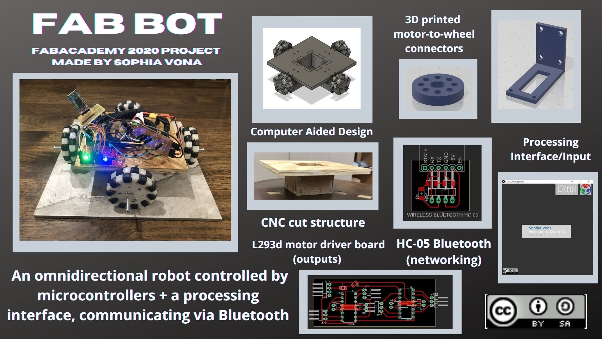
For my final project I wanted to try to make a derivative version of the loveable Star Wars bb8 droid. The droid I will try to make will have a holonomic drivetrain that sits inside a spherical “shell,” and the drivetrain will push the sphere around to make it move (like a hamster running around in a hamster wheel). The head will be magnetically attached, and the motors will be controlled by a processing app on my PC via a bluetooth module.
UPDATE: unfortunately, the scope of my project as envisioned above would have taken longer to complete than the time alloted to finish this project. So, I revised my project to be a robot, still with a holonomic drivetrain, that is controlled bya processing app via Bluetooth.
Video
Slide
License
In week 13, I chose to use a Creative Commons 4.0 License, that allows others to “remix, adapt, and build upon your work non-commercially, as long as they credit you and license their new creations under identical terms.”
Materials
| Part name | in lab? | price | quantity |
|---|---|---|---|
| Atmega328p | yes | x1 | |
| 16mhz crystal | yes | x1 | |
| L293D motor driver chips | https://www.digikey.com/product-detail/en/texas-instruments/L293NE/296-9519-5-ND/379722 | 3.93 | x2 |
| HC-05 | no | 7.99 | x2 |
| gearbox motors | yes | x4 | |
| lipo battery | yes | x1 | |
| 12v battery | yes | x1 | |
| neodynium magnets | yes | x1 pack | |
| ball casters | no | x1 pack | |
| omni wheels | yes (made them) | x4 | |
| wood | yes | ||
| fr | yes | ||
| various resistors/capacitors |
Refer to week 19 for information on project planning, and where I was/ what I still had to do when I stopped working on the individual weeks and went full throttle on the final project.
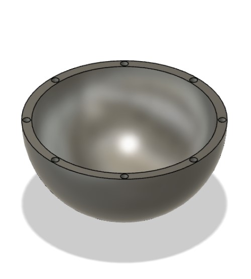
CAD/Mechanical Design for the Shell
This the CAD work I got done in weeks 1-19 (and finished at the start of this week)
Drive train and other internal workings
There are changes in these designs that I talk about making throughout this page.
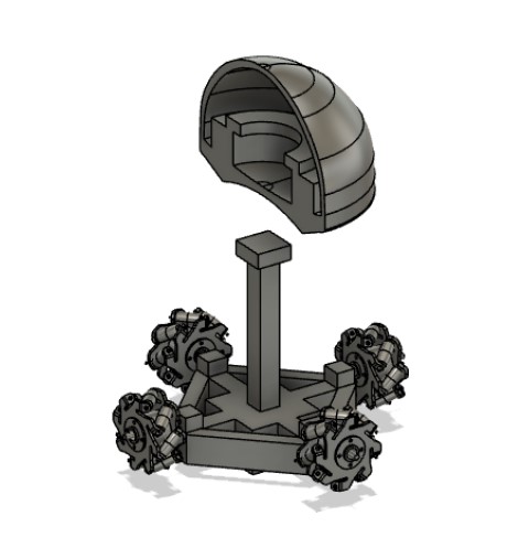
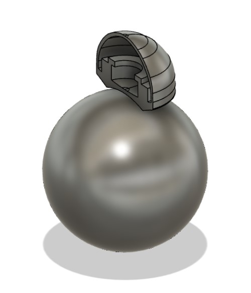
The first file (the first two images) has no visible way of seperating and connecting the “shell” / outside sphere. So, I tried to make the shell so that there were two halves, and I could screw them together using threads. I got the inspiration for this from fab alumn Pietro Rustici’s final projet, a rolling ball called palla (a former fab student). He made a rolling ball robot. A key difference is that I tried to cover the sports where the threaded inserts would be by increasing the thickness of the shell. I had to do this because there will be a drivetrain rolling around the inside of the shell like a hamster. If it rolled over threads it might not move very smoothly.
However, the 3d print failed. It was a lot of material and my tecahers and I were not so sure the 3d printer would be able to print such a large file. I spent a little while trouble shooting with my teachers and trying to figure out a work around, but we weren’t confidant we could find one, so I moved on to trying to make the shell another way.
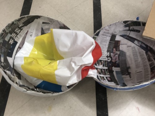
Composite mache shell
I found this instructables by ASCAS of a BB8 robot, and decided to use their idea for a composite-mache shell.
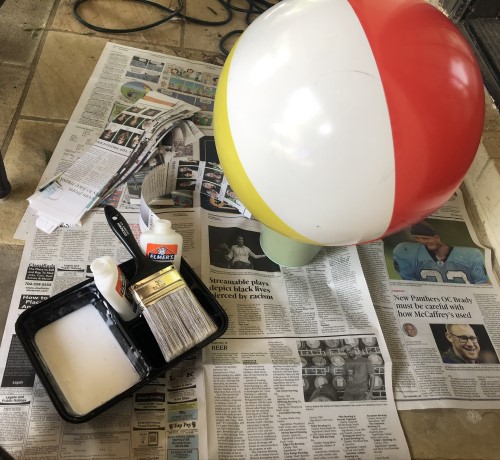
The general idea was to use a beach ball and cover it with multiple layers of paper mache/ canvass mache to create a strong shell. Also- instead of using flour and water, you use PVA glue (aka elmers) and water because it is stronger and will crack less.
I used a beachball in my backyard. I took it’s measurements, and then adjusted the CAD file with the wheels/ drivetrain by scaling the whole thing down slightly.
Here is the procedure:
-
Cut out a ton of strips of newspaper and canvas, all about 2 inches wide, and try to make each strip close to a diameter of the ball in length
-
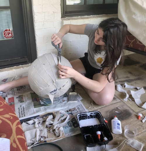
Mix together glue and water in a ratio of 2 parts PVA glue to 1 part water in a ratio of 2 (to slightly dilute the glue). Get a large paintbrush. Find something to prop the beachball up on so it won’t roll away. Also, you should probably be outside/ cover the surface you are using with newspaper for easy clean up later.
- Cover a 2 inch stip of the beach ball in the glue/water mixture with the paintbrush. Lay a strip of newspaper over ball flat. Repeat right next to the first strip. Keep going until you have 1 layer of newspaper strips parallel to each other covering the ball. I originally tried to soak the newspaper strips in the glue mixture as one would do with flour/water paper mache, but it gets really heavy/ falls off the ball. It gets messy fast. Leave it outside to dry completely.
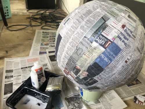
After it dried it seemed a little bit saggy, which worried me. I tried to use less lue/ water mixture for the next layer, and was especially careful to smooth out bumps so it was more or less flat.
-
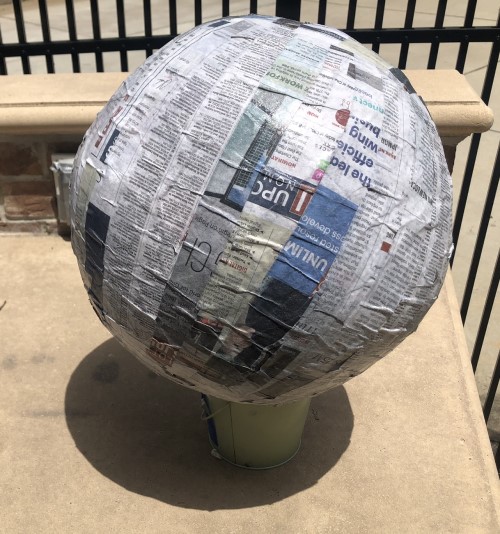
Repeat step 3, but lay the strips perpendicular over the first layer. Let it dry completely.
-
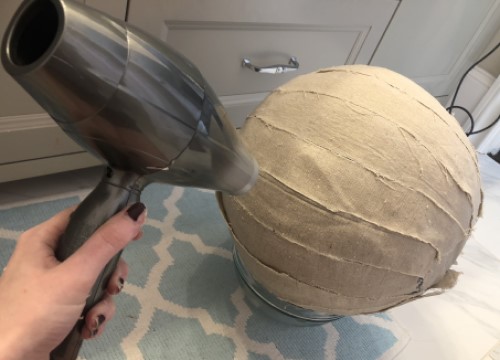
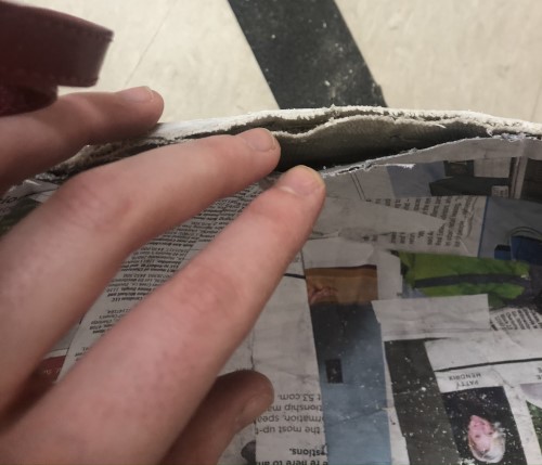
Do step 3, but with canvas. Lay the strips perpendicular to the second layer of paper. Since canvas is a lot thicker, try not to layer multiple strips over each other. I ended up trimming the ends into triangles to try to stop the pieces from overlapping. Also, it was a lot harder to get the paper mache to stick. I had to put a lot of glue over it to stay. It took almost 48 hours for this layer to dry. I had to use my hairdryer to speed up the process, and dab away glue in certain parts.
You can see some edges of the canvas strips weren’t laying flat. Laying a second layer on fixed the first layer edges that popped up, but more edges popped up from the second layer.
- Repeat step 3 with more canvas, perpendicular to the last layer. Leave to dry.
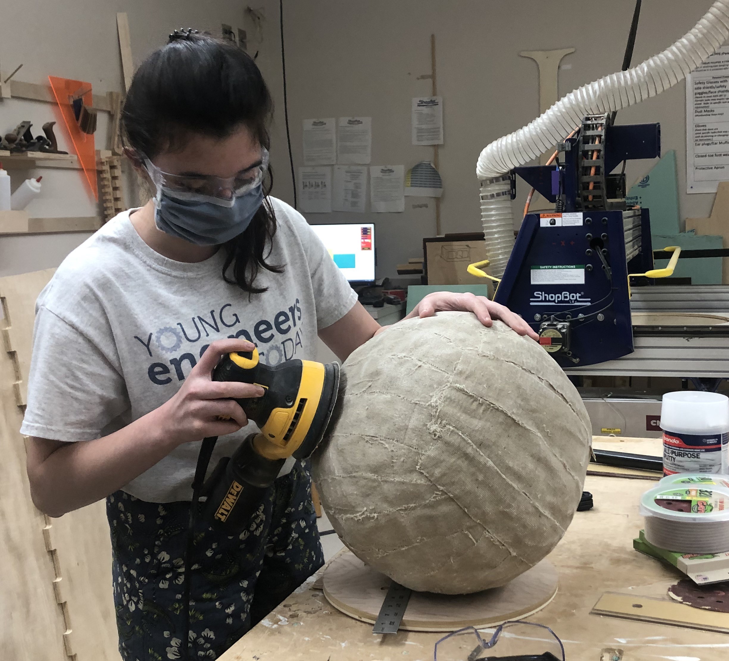
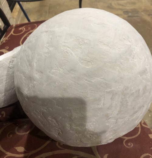
Then I brought it into the lab and used the hand sander to try to smooth out the edges. I started with 300 grit, then increased in increments until I was at almost 1500 grit. I was not able to make it as smooth as I wanted it to be, but it got to the point where some of the canvas edges started to come up. I was afriad I was sanding the glue away, because more of the edges were starting to come up. I ended up simply hot gluing some of those down, which more or less worked.
This next part is not from the instructables. Honestly, I wasn’t happy with how strong it was, and parts kept popping up. Plus, I wanted to smooth out the crevices and lumps that had dried into the shell. I talked to Dr. Taylor, fab alumn and local fab node teacher, and he suggesed I use bondo, an automotive body filler. Using it was complicated. I followed the video tutorial below, but unfortaunately not very well.
The steps:
- Find a flat metalic thing to scoop some bondo onto. Mix a little bit of activator paste with it.
- Use the scoop/ spreader to press a layer onto the surface you are spreading over it.
The complicated part is the technique of spreading it over the material, especially because it dries quickly. I am not sure how to verbally explain how they mixed it/ how they pressed it onto the car they were fixing the dent on, its a visual. If you are using this site as a tutorial, I highly recommend you watch that.
Anyways, it dried really quickly and I ended up with a finish that was not particularly smooth. I tried to practice on some random material first, but I really wasn’t applying the bondo well until I was almost done covering the shell (and the dome/ the head of bb8, which I covered in bondo so the texture of the shell and the dome would be uniform).
After this point I brought it back into the lab and sanded it a bit again with the hand sander- startignw ith grit 300 and working my way up.
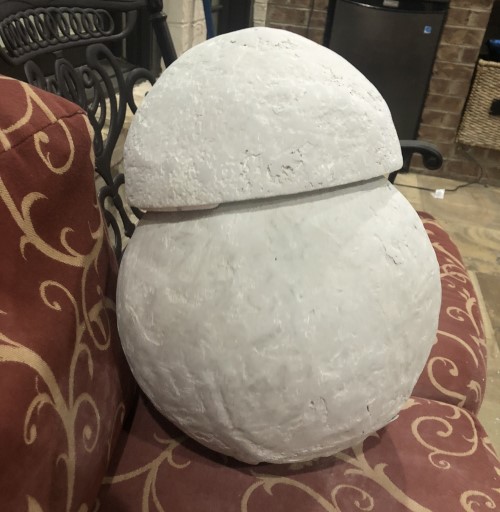
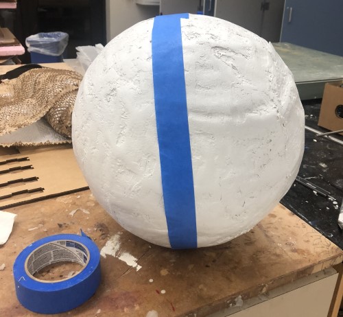
Then I marked the center with a piece of painter’s tape, and used a hacksaw to cut down the middle.
Note- the tape looks way off center in the photo, this is because I lined the edge of the tape up with the middle, so that I had a line to cut along.
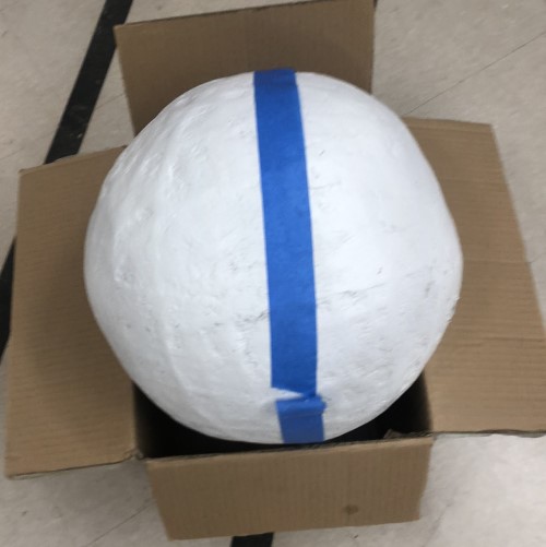
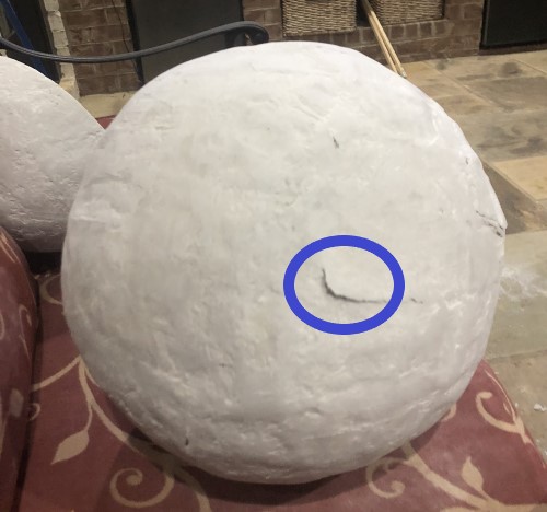
I’m a little wary of how stable this ball is going to be. In the instructables it was a very hard shell. My version is a lot flimsier, even after I added the bondo. Also, the edges almost look like they’re coming apart. I ended up using more hot glue to press them together so they do not fall apart, but they cleasry did not adhere to each other.
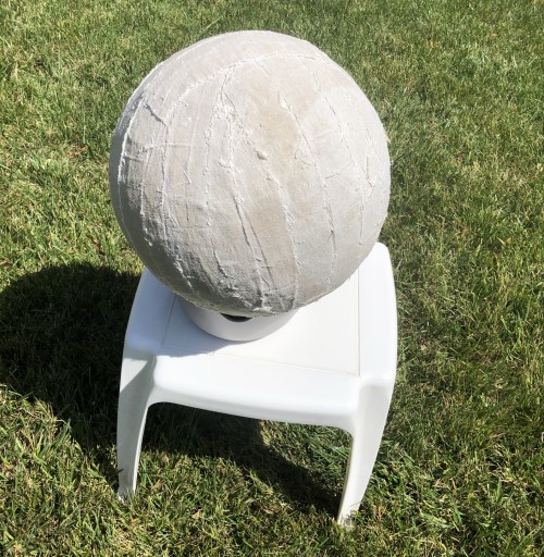
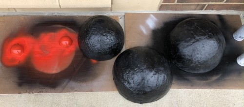
I sprayed both the inside and the outside with flex seal/ plastidip (so it would have a rubbery grip as it moved over the ground, and the places on the inside that came into contact with the wheels would have some friction between them and it would roll better).
I then spray painted the outside black (the back of the plastidip said spray paint could be used over it, and it would still work). BB8 is technically white and orange, but I figured that since this robot would be rolling around on the floor of the fablab/outside on the ground, it would pick up a lot of dirt and start to look filthy quickly. The balck spray piant will disguise that better than the white spray paint.
The plan (for now) is to guct tape the two speheres together as I am testing, and hot glue it for the final presentation. This is very crude, but I know I will constantly need to open it up to replace the batteries. The batteries cannot be attatched to the shell because the drivesystem acts like a “hamster”. Even if I could get rechargeable batteries, I would have no way of plugging them in, because they need to be inside the drivetrain. Recharebale batteries could work if I attatched a power source to the shell but 1) the drivetrain might roll over it and flip over/ simply not roll, and 2) the wire connecting the batteries to the electronics of the drivetrain might get tangled up in the wheels. I guess I will have to do more research into how bb8 is actually charged.
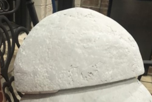
The head (dome)
I used a half of a hollowed out styrafoam ball that I got from a neighbor. The dimensions were approximately in the right ratio to match the shell.
I covered ths with bondo as well (so it would match the shell and it would look smoother than styrafoam) looking back this was a bad idea because I was not very good with applying the bondo, so there were still lots of gaps and holes. The craftsmanship wasn’t pretty. But the aesthetic is the least of my problems with this project, so I left it alone. Hopefully I can make a v2 of this project after fabacademy is over that looks better. I also covered this with black spray paint.
The mechanism that keeps the head attatched to the body is essentially a strong magnet. I will be using neodynium magnets because they are small and strong (plus we had a box laying in the corner of the lab)
To attatch the magnets to the head, I will laser cut a flat piece of cardboard to hot glue to it. I added space to attatch the cardboard to ball bearings, so it would be able to roll around over the top of the shell. I also designed another small laser cut piece that would attatch to magnets + ball bearings. This one would roll around on the inside of the shell, and move with the magnet.
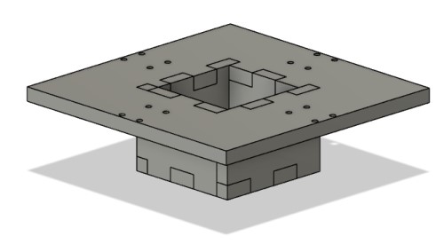
Here is the CAD drawing of those two pieces. This is an updated version of the Cad drawing from earlier. The top two parts are for the dome, the rest is for the drivetrain, and will be explained later. Note: The Semi circle and the sphere have measurements based off the beach ball and the styrafoam hafl sphere I have in real life.
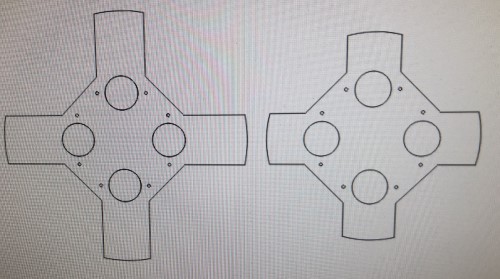

Here is both of them cut out, and with the ball bearings/ neodynium magnets attathced. I had to experiment a little bit with the hot glue to get a lot of magnets to lay flat on the laser cut cardboard. I also noticed that the edges of the piece that went inside the shell were scraping the edges of the shell ever so slightly, so I trimmed the edges off with the band saw.
After that, I screwed in the ball bearings, and hot glued the magnets on.
I wasn’t really sure to test this until after I had the ball rolling around, which I do not yet. If you look at the video, the dome doesn’t fall off, even when it’s upside down, which makes me confidant that the magnets are strong enough to hold the dome on when it isn’t upside down (which it shouldn’t be, outside of testing). It’s a little hard to tell what the second part of the video is, but I started tilding it and the dome rolled off. At the end it fell off the edge.
It’s rolling really fast, which worries me. If the robot does not go fast enough to keep the head from falling off, I’m afraid the head won’t stay upright.
Also, I don’t know what to do about the edges. Even after I tape them together, I do not know how they will effect the mechanism that holds up the head. The rollers might get caught on it, and the magnets might fall off. I’m not entirely sure what to do about it until I test it when the ball is together and the drivetrain is actually rolling at the speed it will be pushing the ball. So for now, I am going to leave the number of magnets be/ not change anything. I will revisit this issue in the “Putting it all together” section of this page.
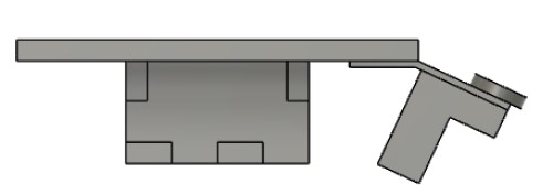
One idea is to make it seem more like this image:
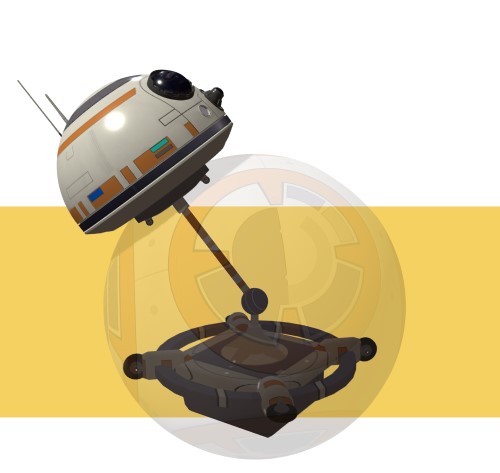
If I attached the laser cut plate with the magnets on the inside of the shell to long piece of wood, and attatched that piece of wood to the drivetrain, then the drivetrain will stop the dome from rolling too quickly and falling. But like I said, I won’t change it until Ican actualy test it with the working drivetrain.
This image above is from how bb8 works.com, a fansite discussing possible mechanisms for how bb8 works. The only difference my robot would have is the rod would always be straight up, it would not be attached to a motor and spin around like that.
Drivetrain
The goal of this robot is to have a holonomic (capable of moving in any direction) robot. To do this, I am planning on making a drivetrain that rolls around inside the shell like a hamster moving in a wheel.
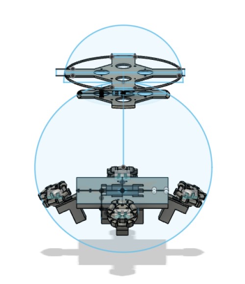
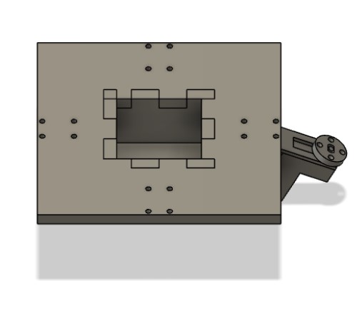
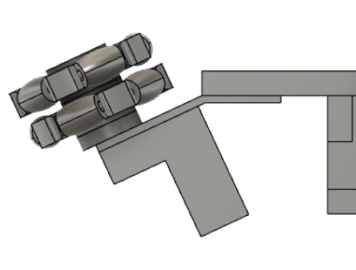
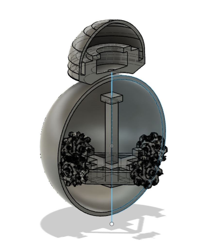
Here is an image of the drivetrain. This is a new cad drawing, edited from the ones shown above.
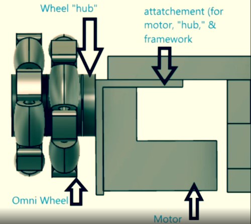
Here’s a breakdown of that CAD drawing:
The wheels are omnidirectional wheels, which means they can move roll like normal wheels, and the rollers allow them to also move perpendicular to the direction wheels normally move. I followed this tutorial on youtube to create the wheels. I modified it slightly, so that there would be more rollers. I was afraid that in the original design that the space between the rollers might just catch and drag on the inside of the spehre, so I made the space in between rollers smaller. There is also a significant amount of space in between the inside of the roller and the “axel” in the center of it that held it up. I am afriad that when the roller is placed against the inside of the shell it will be pushed back so far that the actual roller part doesnt tuch msot of the shell, and it drags. So, I made the radius of the roller a little bigger.

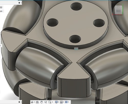
(It’s hard to see, but there is space in between the rollers and the axis)
I started by printing one wheel first to test out the design. I then removed all the supports with a pair of clippers and by hacking at it with some tweezers. It was not the most graceful of methods, but it worked. I then sanded out the rollers to make it smoother.
Proof of concept video wheel spinning
I also figured there would need to be some grip between the rollers/wheel and the inside of the shell. I had some bottles of plastidip/ flexseal on hand, and usually the rollers are coated in rubber. However, I was not super confidant of my ability to spray the plastidip evenly enough around the rollers evenly so the roller would still be smooth. Also, I was afraid plastidip would dry in between the roller and the axel, and then the roller would not be able to turn smoothly. So, I talekd to Dr. Taylor (fab alumn and teaher at our fab node) and he suggested that I spray the plastidip on the inside of the shell, he thinks having the shell be ruberized will work similarly to if the roller was rubebrized.
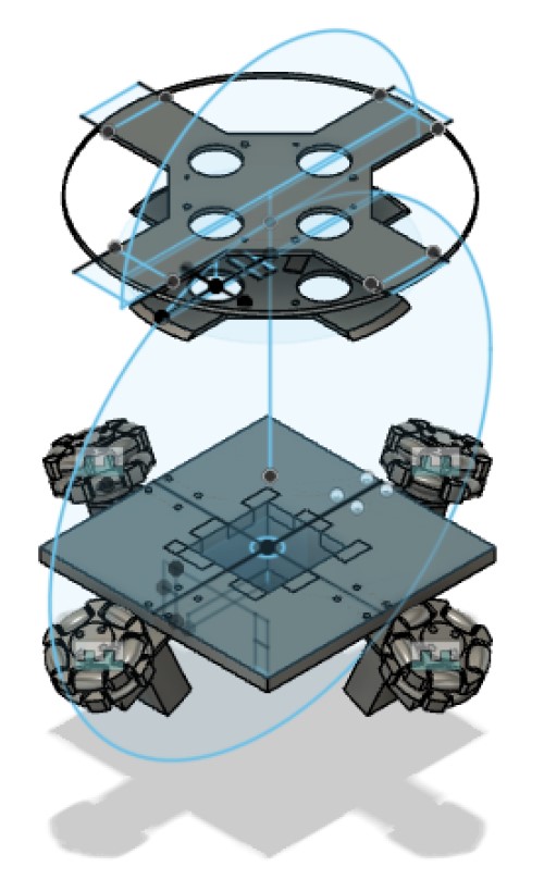
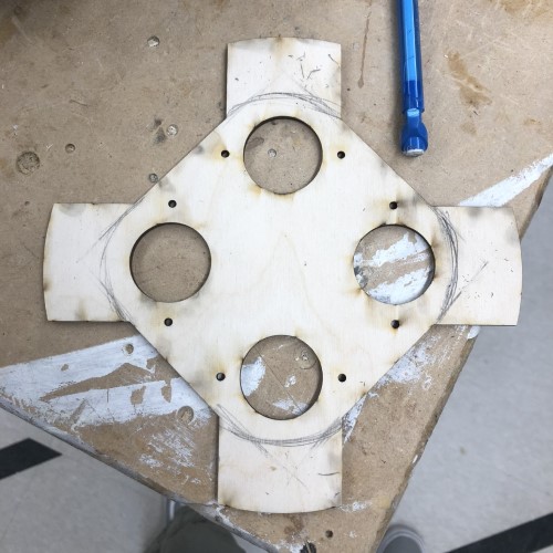
The main structure (in the middle) would be CNC’d from .373 inch wood. It has a small “compartment” jutting out the bottom where I will place batteries. This will also help add a bit of weight. I want the center of gravity to be low, that will help it balance.
There are little 3d printed components that are screwed into the main structure of wood. I measured the gearbox motors and designed the 3d printed parts to fit around them and have a spot to screw them together. I also designed a little connector plate that fit into the gearbox motor axil, and tried to design it so that they would have holes that aligned with the wheels. I was able to make a connector plate that fit into the axil of the motor. It has a really tight fit, but one of them kept popping out of the axel, so I hot glued it onto the axel. The connector plate also has holes in it that align to the holes in the wheels, so I screwed them together.
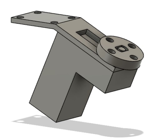
Note: the connector and the axel do not appear to have a snug fit, but this photo was taken after I accounted for the 3d printer. The first time I printed it, the diameter printed a few mm too small, so I added a few mm to the diameter of the connector to get the right fit.
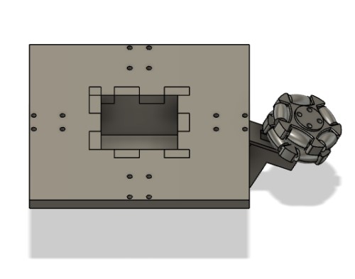
The wheels will be at a 45 degree angle to the shell, so as much of the surface area of the rollers as possible comes into contact with the inside of the shell.
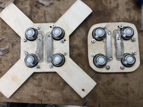
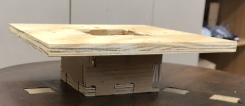
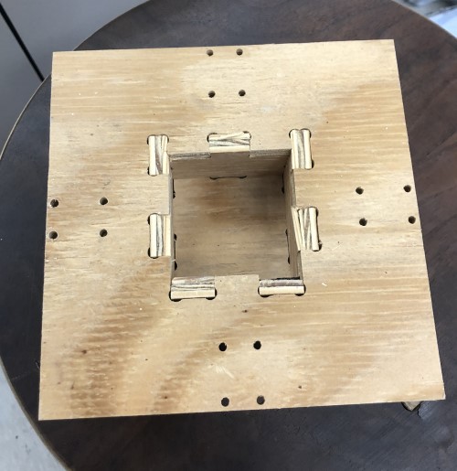
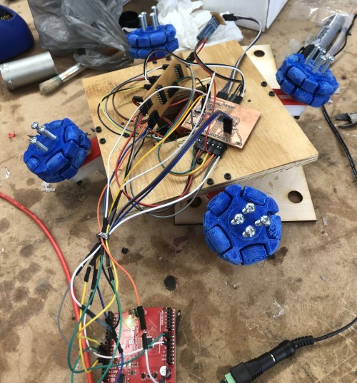
The drivetrain fully assembled(minus the electronics):
Electronics
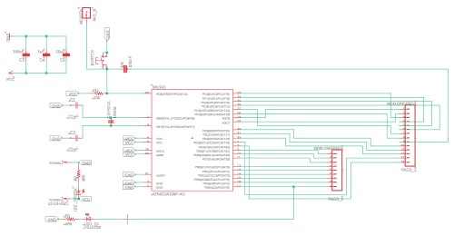
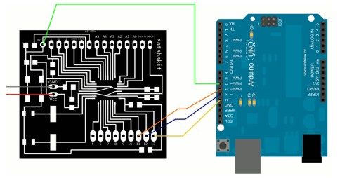
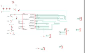
For this project to do what I want, I need something to control the motors, and something to convey input data from a processing app to the motors. I decided to build this board by making a modified satshakit. I downloaded the board and schematic file of the satshakit site, made sure they were in the same folder so that when I changed one file it would update the other, and started to modify the files.
Satshakit schematic:

Output
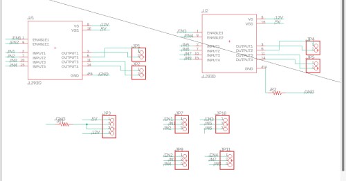
I have 4 BLDC gearbox motors, so I will controll them with 2 L293D motor drivers. Controlling the motor will be similar to what I did in week12, output week I used this site and a picture of the l293d pinnout from that site to come up witha basic schematic for an l293d to an arduino (or satshakit). The pinnout for the motor drivers is as follows:
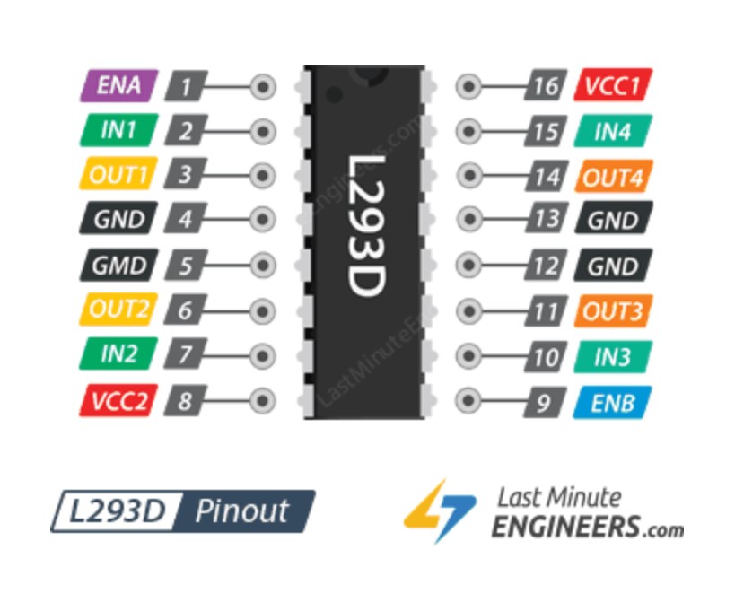
The basic idea is that the three wires of each motor need to be conencted to three pins: two OUTPUT pins (labeled OUT 1, 2, 3 and 4) and the GND pins (there are 4 GND pins, and they should all be connected to each other).
Each OUT pin (1, 2, 3, 4) has a corresponding INPUT pin. The output pins are attached to the motors, and the input pins are attatched to the arduino (satshakit) digital pins.
The data relayed to the input pins from the microcontroller are relayed to the outputs pins,a d this controls the direction and speed of the motor. For example: If the satshakit wrote a “high” to input pin 1, then output pin 1 would send power to the motor, and the motor will spin in one direction. If the satshakit wrote “high” to input pin 2, the output pin 2 would send power to the other wire of the motors, and it would spin in the opposite direction. Note: 1 motor must be attatched to in and out 1/2, and the other must be attatched to in and out 3/4. You shouldn’t attatch one motor to 1 and 3, and another to 2 and 4, because the way it controls the direction is through an H-bridge inside the L293d chip, and for it to work they must be in the appropriate pairs.
The output pins also control speed by conveying how much power to send to the motor. There are 2 ENABLE pins that connect to arduino/satshakit pins. They take inputs of 0-250, and the output power will send more current for higher numbers, causing the motor to spin at a faster speed, and a lower amount of current for a lower number (lower speed).
The ground pins should all be connected to each other. There are two voltage inputs: Vcc 1 is for the internal logic circuitry- meaning it connects to the satshakit microcontroller and uses a 5v input. The other voltage input is for the motor- which can handle anywhere from 4.5v to 36v (choose the voltage based on the specifications of the bldc).
Here is an eagle schematic of the l293d part:

I named all the wires, and renamed wires on the satshakit so that the program would connect them.
Input
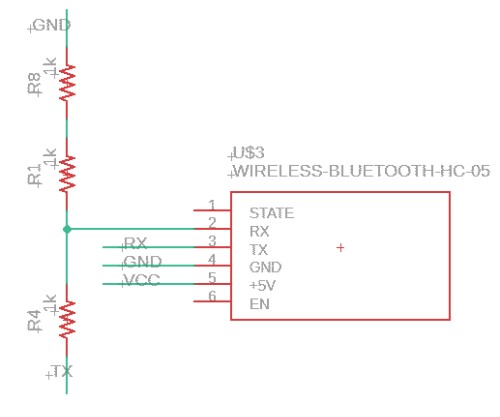
I also needed to add a bluetooth module to the board. This will trasmit the “input” data from the processing app to the satshakit and the motors, so the processing app can control the motors.
There is more documentation of how I did this during week15, networking and communications.
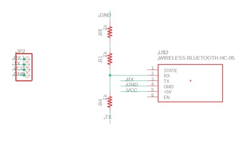
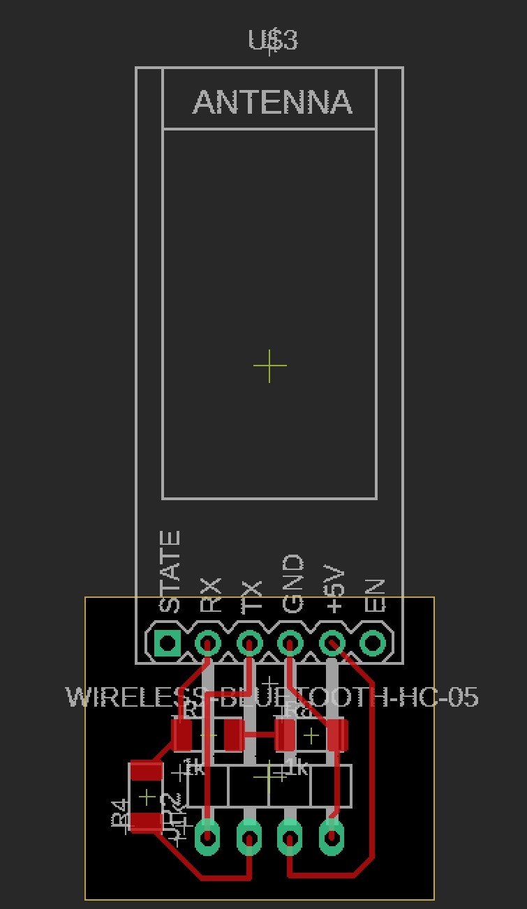
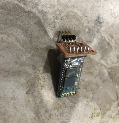
I followed this tutorial and used the schematic below (from the video tutorial) to make the bluetooth connections.

Here is the module:
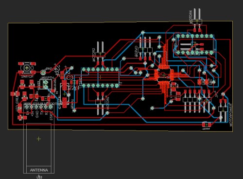
Here is the schematic all together:
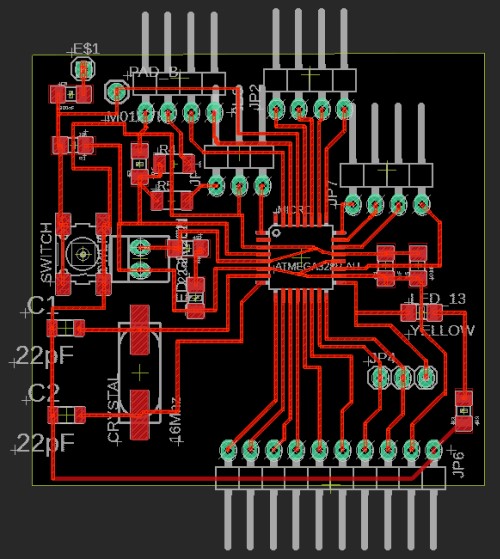
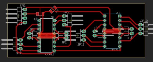
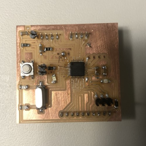
Here is the board, you can see that it is double sided. This was the only was I could figure out to get all the components on one board.
Milling, Soldering, and Testing the Electronics
I uploaded the board file to eagle (just by dragging and dropping the file in) and milled the board. I made the bottom layer and the vias (holes) “invisible,” and milled the top. I then flipped the board around, being careful to align it perfectly to the side of the bracket, and milled out the bottom part out, this time with the vias.
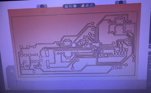
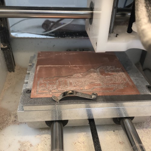
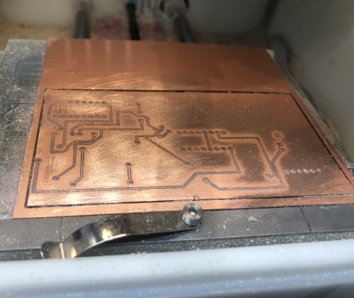
I sanded both sides, used an exacto knife and some tweezers to scrape away parts that shouldn’t be ont he board but weren’t quite removed by the sanding, then cleaned the board. I noticed the first board had some traces so thin that the mill had problems milling them. I had just stuck to the trace width that was on the downlaoded satshakit files, but I figured i had to change the trace width size. I asked fab alumn and local node teacher Mr. Rudolph, and he said that changing the trace to 20 or so width would make it easier to solder, easier to not rip a trace, and the traces would mill out much straighter/better. So, I changed as many rtaces as I could to width 20 using the “change width” tool on eagle, and I changed the settings so that there was more space more and left the ones that I couldn’t make any bigger (because they would overlap with something otherwise) alone. The second board (on the bottom) turned out much better.
First bord- bottom. Second adjusted board- top
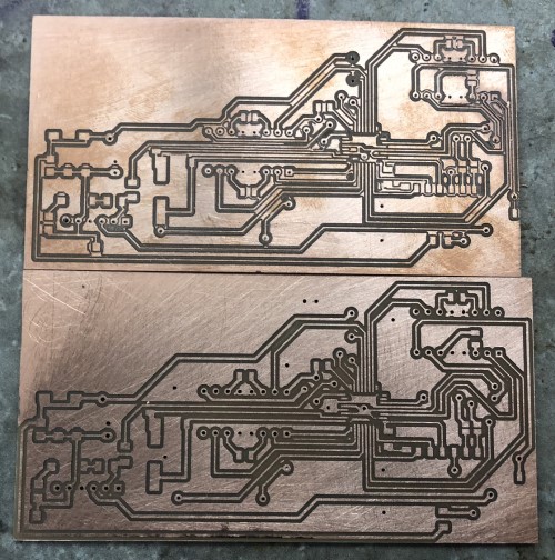 (front)
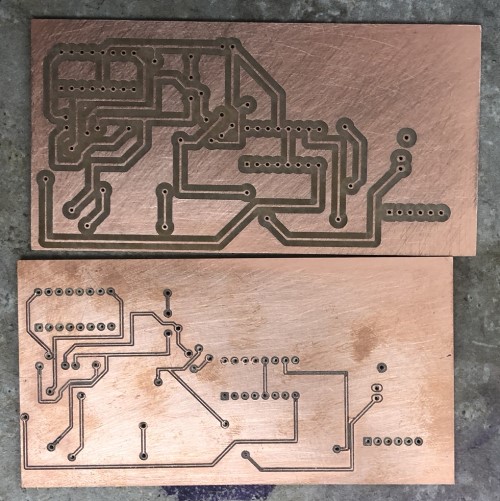 (back)
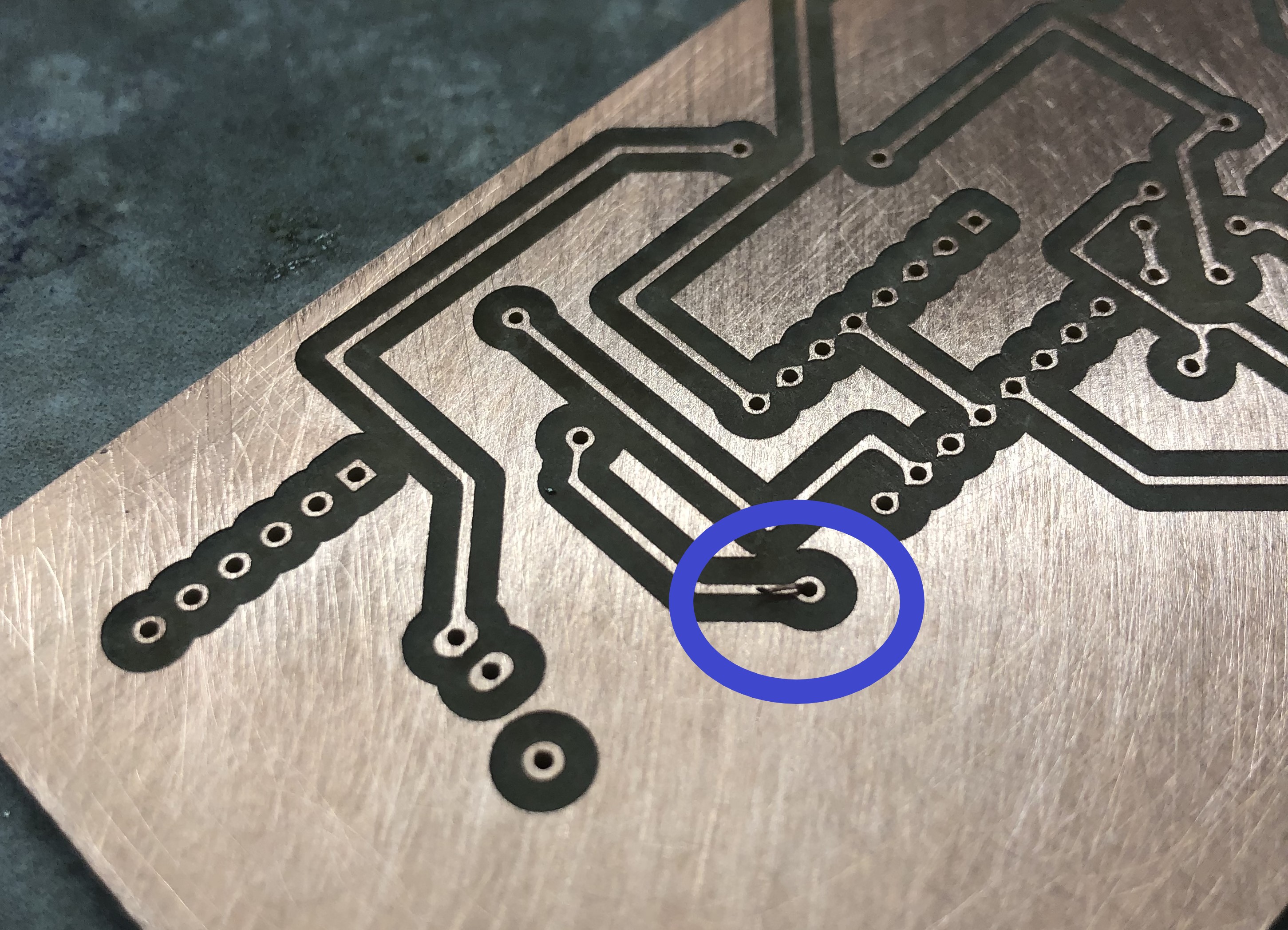
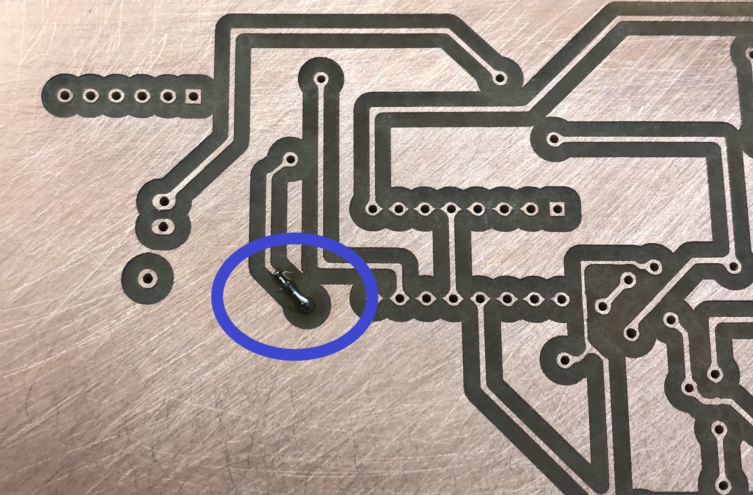
I then started to connect the bottom traces to the top through the vias. I got some wire and threaded it through the hole, soldered one side to the pad, soldered the other side, then clipped the wire. It doesn’t look particularly special- but this is what the first via looked like:
I finished the rest of the vias, and finished soldering the board. I plugged the power/ gnd into a battery. The LED connected to gnd and power went on, which I believe is a good sign. I follwed the instructions on the satshakit site to burn the bootloaders and program the board, which are as follows:
- Make the connections between an arduino and the satshakit as seen below. The arduino will be the programmer board.
- Open Arduino IDE
- Select proper programmer by clicking on Tools->Programmer (for example USBtinyISP)
- Select Arduino UNO as Tools->Board
- Click on Tools->Burn Bootloader
It uploaded normally, without throwing any error messages. After I did this, I uploaded a simple blink skecth to make sure everything had worked.
If you look closely at the video- you can see something I missed at first (that will be important below, when I talk about problem #1 with the electronics) The satshakit pin 13 and the arduino pin 13 are connected because this is one of the pins for isp programming (isp connections are used to burn bootloaders/ program an arduino/satshakit). Pin 13 also has the build in LED’s attatched.
Problems and Revised Board
Problem #1)
The first problem I ran into was that my board was never actually successfully flashed the bootloaders. When I tried to run the code for the motors (below, in the software section) and it never worked. I didn’t get any upload errors either, so I assumed everything was fine. I spent a lot of time going over the software looking for issues, but the code was fine (more or less). I has dimply assumed the board was working because the blionk code had worked, but then I uploaded the motor code to a normal arduino it worked (actually, it didn’t do exactly what I wanted on the first go. But I could tell that stuff was happening, the motors were at least turning, which was more than was happening with my satshakit).
After that I went to talk to our fab guru/fab alumn Dr. Harris. He helped me conclude that although I was not getting any error messages, for some reason I was unable to program the board. The reason I thought the blink code was working for the satshakit was because the “build in LED” used on the blink sketch is on pin 13. Pin 13 on the arduino was connected to pin 13 on the satshakit because this is an ISP programming pin that you have to connect to burn the bootloaders, and you have to connect GND as well. He realized that it was only blinking because power was flowing from the functional arduino (which was being programmed instead of the satshakit- even though we confirmed that I had followed the steps correctly and that the satshakit should be the target board, not the arduino).
Anyways, I tested connections between the satshakit pins and eventually found a short from a solder bridge between TX and RX, and a couple of other digital pins. After I fixed this, I was able to burn the bootloaders and upload the code.
That leads us to problem #2)
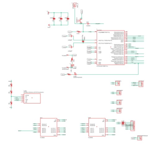
After I fixed the shorts I was able to upload the code. This time, it did what it was supposed to do, It ran one motor and switched directions ever couple of seconds. When probing with an oscilloscope, it seemed that the atmega328p would simply stop giving off pwm signals to the enable pins. The input pins seemed to still give off values, but the motors still would not run. After troubleshooting with Dr. Harris, fab alumn and local fab node guru, we were unable to isolate the problem. He suggested that it was probbaly because my capacitors/ clock and other components were so far away from the atmega 328p chip, that it may be casuing problems. However, since the board was so massive, we never exactly found what was casuing the problem. I had to make a new board. For the next iteration, Dr. Harris sugested I build it in modules: 1 for the satshakit, 1 for the motor drivers, and one for the bluetooth module. That way, if something was going wrong, I could test each module and figure out which part wasn’t working (and only have to replace some parts, not all, of the parts if something went wrong again).
So that’s what I did. Below you can see the designs for new schematics/ boards for a satshakit, a motor driver board, and a bletooth module that could all plug into each other.
Satshakit:
Motor driver:
Bluetooth module:
I succesfully uploaded the code this time, and got it working.
Here it is: along with the assembled drivetrain (not in the shell yet though) all working:

Until… Problem #3)
Picture this- it’s 3AM. A sleep-deprived fabacademy student is trying to work on the code for her final project so she can keep on schedule with her gaant chart. She picks up the boards, which are plugged in, powered, and running code, and tries to shift them over so the wires don’t get caught in spinning motors. Suddenly- everything stops. The girls computer shuts off for a minute- and she unplugs all the batteries. But it’s too late.
Luckily, the computer turned back on, but then boards chips were fried. After I tried to program them again, they wouldn’t run any code. What probably happened is the power for the motors- 12v- was shorted to the satshakit 5v power. I asked my teachers and they said that is definetely enough to fry a chip. It ran back up to the com port and shut off my computer.
This actually happened a few days before I was supposed to present. I made new boards, and I was able to get a functioning bluetooth module and motor driver module, but for some reason I couldn’t get the satshakit put together in time. I actually made two, the first one shorted again! In the next iteration, I removed the pin for VCC2 (the pin for the motor high voltage) from the satshakit. Instead, I put it on the motor board. I made another board, but I just never got it to work. That was the only change I had made. It must have been something int he way I soldered it, but it just never ran any code- I couldn’t get the bootloaders to burn. I spent an awful lot of time troubleshooting, but I couldn’t figure it out. At this point, we were a few days away from the duedate, so under the advice of Mr. Dubick (our local teacher at the Charlotte Latin Fablab) I simply used an arudino. I still had other hurdles to get over, and I couldn’t make progress on any of them because I was suck on the satshakit. I ended up having to present my project with an arduino on it, because I just never got one done. I explained what happened to Niel, and he mas merciful(thank you Niel!!)- he said it was fine as long as I was eventually able to get a satshakit working and to document it.
So lo and behold, here is the final satshakit (made after final project presentations). I still never figured out exactly what went wrong with the old boards (except the ones I shorted).
Here is a video of the satshakit that I made after final project presentations, just proving that it works:
Hero shot:
You can also find this fix in the “putting it all together” section of this webpage
Software
The plan was to send data from processing to the atmega 328p, via the bluetooth chip. I started with this tutorial. I then worked on making the Processing code send joystick values for a while, but was ultimately unable to get that to work. The motors would turn in one direction, but not in the other (when the joystick input was changed to make the motors turn backwards). I believe there is something wrong with either the logic of the if statement (controlling forwards and backwards) or there is an issue with the data that it being send through) I have included the joystick code and a more simple code, which allows you to activate a hardcoded program on the atmega328p board from processing.
Joystick Arduino:
//define l293d motor input pin as the arduino pin it is connected to

#define Motor1A  7
#define Motor1B  8
#define en1  6   //motor 1

#define Motor2A  10
#define Motor2B  12
#define en2  5   //motor 2

#define Motor3A  A5
#define Motor3B  A4
#define en3  11   //motor 2

#define Motor4A  A3
#define Motor4B  A2
#define en4  9   //motor 4

//define servo pin

//kinematics setup
  byte X = 0;
  byte Y = 0;
  int X1 = 0;
  int Y1 = 0;
  bool dirX = false;
  bool dirY = false;
  float speedX = 0;
  float speedY = 0;

//parse data setup
  const byte numChars = 32;
  float receivedChars[numChars];
  float  tempChars[numChars];        // temporary array for use when parsing

      // variables to hold the parsed data
float receivedChar;
boolean newData = false;

void setup() {

  Serial.begin(9600);
  pinMode(LED_BUILTIN, OUTPUT);

//set all pins to outputs

  //motor 1
  pinMode(Motor1A, OUTPUT);
  pinMode(Motor1B, OUTPUT);
  pinMode(en1, OUTPUT);

  //motor 2
  pinMode(Motor2A, OUTPUT);
  pinMode(Motor2B, OUTPUT);
  pinMode(en2, OUTPUT);

  //motor 3
  pinMode(Motor3A, OUTPUT);
  pinMode(Motor3B, OUTPUT);
  pinMode(en3, OUTPUT);

    //motor 4
  pinMode(Motor4A, OUTPUT);
  pinMode(Motor4B, OUTPUT);
  pinMode(en4, OUTPUT);

//set initial state of all motors as "Off" or "Low"

  digitalWrite(Motor1A, LOW);
  digitalWrite(Motor1B, LOW);
  digitalWrite(Motor2A, LOW);
  digitalWrite(Motor2B, LOW);
  digitalWrite(Motor3A, LOW);
  digitalWrite(Motor3B, LOW);
  digitalWrite(Motor4A, LOW);
  digitalWrite(Motor4B, LOW);
}


void loop() {
    digitalWrite(LED_BUILTIN, HIGH);
    delay(2000);
////////////////////////////////
  if (Serial.available() > 0) { //read bytes when serial has more than two bytes availible
        byte X = Serial.read();
        delay(10);
        byte Y = Serial.read();

        //transform from bytes to int
        int X1 = (int) X;
        int Y1 = (int) Y;

        //tranform it so values from processing are like values on a cartesian plane.

        X1 = (X-127);
        Y = (-1*(Y-127));

        //set directions

        if(X1>0) {
        dirX = true;  // (if dirX = true, x motors go forwards)
          }
          else{
            dirX = false;
            }

          if(Y1>0) {
            dirY = true;  // (if dirX = true, x motors go forwards)
          } else {
            dirY = false;
            }

          //set speeds

          speedX = (2*(abs(X1)));
          speedY = (2* (abs (Y1)));

          newData = true;

/////////////////////////////////////
  }
  motors(dirX, dirY, speedX, speedY, newData);
}


void motors(bool a, bool b, float c, float d, bool e) {
    if (newData == true) {
      digitalWrite(LED_BUILTIN, LOW);
      delay(2000);

//x axis
      if(a = true) {

        digitalWrite(LED_BUILTIN, LOW);
        delay(2000);


//motor 1 and 2
        digitalWrite(Motor1A, HIGH);
        digitalWrite(Motor1B, LOW);
        analogWrite(en1, speedX);

        digitalWrite(Motor2A, HIGH);
        digitalWrite(Motor2B, LOW);
        analogWrite(en2, c);
      }


      else {
        digitalWrite(Motor1A, LOW);
        digitalWrite(Motor1B, HIGH);
        analogWrite(en1, c);

        digitalWrite(Motor2A, HIGH);
        digitalWrite(Motor2B, LOW);
        analogWrite(en2, c);

      }
//y axis
      if(b = true) {
        //motor 1 and 2
        digitalWrite(Motor3A, HIGH);
        digitalWrite(Motor3B, LOW);
        analogWrite(en3, d);

        digitalWrite(Motor4A, HIGH);
        digitalWrite(Motor4B, LOW);
        analogWrite(en4, d);
      }


      else {
        digitalWrite(Motor3A, LOW);
        digitalWrite(Motor3B, HIGH);
        analogWrite(en3, d);

        digitalWrite(Motor4A, HIGH);
        digitalWrite(Motor4B, LOW);
        analogWrite(en4, d);

      }


      newData = false;

      return(newData);

    }
}
Joystick processing:
import processing.serial.*;


Serial motor_port; //outgoing btMOTOR port

void setup () {
  //screen:
  size(1020, 1020);
  background(51);

  //serial
                                       motor_port = new Serial(this, "COM11", 9600);
 //  motor_port.bufferUntil('\n');


}


 void draw() {
     background(51);
     fill(0x00000000);
     circle(510, 510, 200);

     strokeWeight(2);
  //   stroke(0xffaa0000);
     fill(0xffaa0000);
     circle(mouseX, mouseY, 130);


  //  println(hex(byte(mouseX/4)));

    motor_port.write(hex(byte(mouseX/4)));
    println("X=");
    println(2*(mouseX/4)-127);
    motor_port.write(hex(byte(mouseY/4)));
    println("Y=");
    println(2*(mouseY/4)-127);
    delay(20); //needed?


  }
Simple activation arduino:
#define Motor1A  7
#define Motor1B  8
#define en1  6   //motor 1

#define Motor2A  10
#define Motor2B  12
#define en2  5   //motor 2

#define Motor3A  A5
#define Motor3B  A4
#define en3  11   //motor 2

#define Motor4A  A3
#define Motor4B  A2
#define en4  9   //motor 4


void setup() {
  // put your setup code here, to run once:
  Serial.begin(9600);

  //motor 1
  pinMode(Motor1A, OUTPUT);
  pinMode(Motor1B, OUTPUT);
  pinMode(en1, OUTPUT);

  //motor 2
  pinMode(Motor2A, OUTPUT);
  pinMode(Motor2B, OUTPUT);
  pinMode(en2, OUTPUT);

  //motor 3
  pinMode(Motor3A, OUTPUT);
  pinMode(Motor3B, OUTPUT);
  pinMode(en3, OUTPUT);

    //motor 4
  pinMode(Motor4A, OUTPUT);
  pinMode(Motor4B, OUTPUT);
  pinMode(en4, OUTPUT);


  pinMode(LED_BUILTIN, OUTPUT);
}

void loop() {

  digitalWrite(LED_BUILTIN, HIGH);   // turn the LED on (HIGH is the voltage level)
  delay(2000);                       // wait for a second


  if (Serial.available() > 0) { //read bytes when serial has more than two bytes availible
  /*  int X = Serial.read();
    delay(10);
    int X1 = (int) X;
    if (X1 == 1) {

    */
//forwards
      //motor 1
  digitalWrite(Motor1A, LOW);
  digitalWrite(Motor1B,   HIGH);
  analogWrite(en1, 0);


//motor 2
  digitalWrite(Motor2A, LOW);
  digitalWrite(Motor2B,   HIGH);
  analogWrite(en2, 0);

//motor 3
  digitalWrite(Motor3A, HIGH);
  digitalWrite(Motor3B,   LOW);
  analogWrite(en3, 175);


//motor 4
  digitalWrite(Motor4A, HIGH);
  digitalWrite(Motor4B,   LOW);
  analogWrite(en4, 175);

  digitalWrite(LED_BUILTIN, LOW);    // turn the LED off by making the voltage LOW
  delay(2000);

  //////////////////////
  ///back
        //motor 1
  digitalWrite(Motor1A, LOW);
  digitalWrite(Motor1B,   HIGH);
  analogWrite(en1, 0);


//motor 2
  digitalWrite(Motor2A, LOW);
  digitalWrite(Motor2B,   HIGH);
  analogWrite(en2, 0);

//motor 3
  digitalWrite(Motor3A, LOW);
  digitalWrite(Motor3B,   HIGH);
  analogWrite(en3, 175);


//motor 4
  digitalWrite(Motor4A, LOW);
  digitalWrite(Motor4B,   HIGH);
  analogWrite(en4, 175);

  digitalWrite(LED_BUILTIN, LOW);    // turn the LED off by making the voltage LOW
  delay(2000);


///////////////////////////part 2:

//left?

//motor 1
  digitalWrite(Motor1A, HIGH);
  digitalWrite(Motor1B,   LOW);
  analogWrite(en1, 175);


//motor 2
  digitalWrite(Motor2A, LOW);
  digitalWrite(Motor2B,   HIGH);
  analogWrite(en2, 175);

//motor 3
  digitalWrite(Motor3A, LOW);
  digitalWrite(Motor3B,   HIGH);
  analogWrite(en3, 0);


//motor 4
  digitalWrite(Motor4A, LOW);
  digitalWrite(Motor4B,   HIGH);
  analogWrite(en4, 0);

  delay(2000);

  //right

//motor 1
  digitalWrite(Motor1A, LOW);
  digitalWrite(Motor1B,   HIGH);
  analogWrite(en1, 175);


//motor 2
  digitalWrite(Motor2A, HIGH);
  digitalWrite(Motor2B,   LOW);
  analogWrite(en2, 175);

//motor 3
  digitalWrite(Motor3A, LOW);
  digitalWrite(Motor3B,   HIGH);
  analogWrite(en3, 0);


//motor 4
  digitalWrite(Motor4A, LOW);
  digitalWrite(Motor4B,   HIGH);
  analogWrite(en4, 0);

  delay(2000);


    }


  }
Simple activation processing:
import processing.serial.*;

PImage one;
PImage two;
PImage three;


Serial motor_port; //outgoing btMOTOR port

void setup () {
  //screen:
  size(1020, 1020);
  background(51);
  one = loadImage("CharlotteLatinLogoWhite-01.jpg");
  two= loadImage("Fab_Lab_logo.jpg");
  three= loadImage("cc_icon.jpg");


  //serial
  motor_port = new Serial(this, "COM11", 9600);
 //  motor_port.bufferUntil('\n');


}


 void draw() {
     background(51);
     textSize(42);
     fill(211,211,211);
     rect(225,  460, 550, 150);
     fill(0, 102, 153);
     text("Sophia Vona", 305, 510);
     fill(255, 255, 255);
     text("Holonomic Droid V1", 305, 550);
     fill(0, 102, 153, 51);
     text("Start in 3...2...1", 305, 590);

     image(one, 600, 0, width/4, height/8);
     image(two, 875, 0, width/8, height/8);
     image(three, 10, 945, width/6, height/16);

  //   image(two, 0, 0);
  //   image(three, 0, 0);


  //  println(hex(byte(mouseX/4)));

    motor_port.write(hex(byte(mouseX/4)));
    println("X=");
    println(2*(mouseX/4)-127);
    motor_port.write(hex(byte(mouseY/4)));
    println("Y=");
    println(2*(mouseY/4)-127);
    delay(20); //needed?


  }
The code that I used in the video is the “simple activiation sketch.” To make the car go, you simple have to wave your mosue around.
Putting it all together
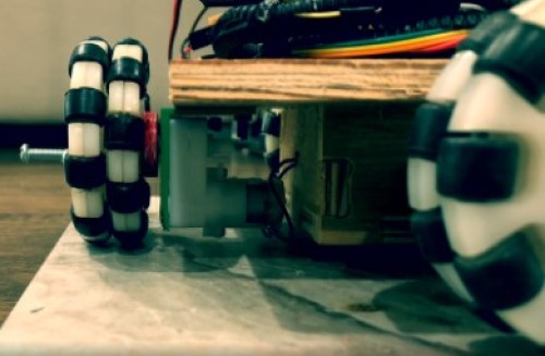
I finally had all the parts together- I assembled everything, and this happened:
Cool! So it’s the day before the final project, and clearly I did not leave enough time to fix this kind of a problem. I talked to Dr. Fagan, our fab guru, and he said what was likely happening was the wheels weren’t pushing up against the shell enough. The wheels were going up/dow as it tried to move, and there wasn’t really enough traction on the inside of the ball. I tried to coat the inside (and the outside) with another layer of plastidip for more traction, but I really only half expected that to work anyways. The bigger problem is that the drivetrain shifts around inside of the ball instead of having the wheels stay firmly on the inside and push. I was able to semi-prove that with this video:
I pushed the shell together so that the ball would absolutely be touching all parts of the rollers, and it moved. I’m assuming part of the problem was the fact that the shell was so flimsy- the wheels were simply pushing the shell out, not actually roling over it and pushing it along as it moved. Dr. Faban said the best way to fix this was to use spring loaded motors, but at this point I had run out of time to fully design/test/implement these. The shell The final presentation date (at the time I am writing this) was tomorrow.
At this point, I talked to Mr. Dubick, and he pointed out that there was really no reason that I had to make a bb8 robot. I had checked off all the items necesary for a final project- input, output, electronics (except for the satshakit issue), with just the robot. He said I could present that as a final project and it should still be fine.
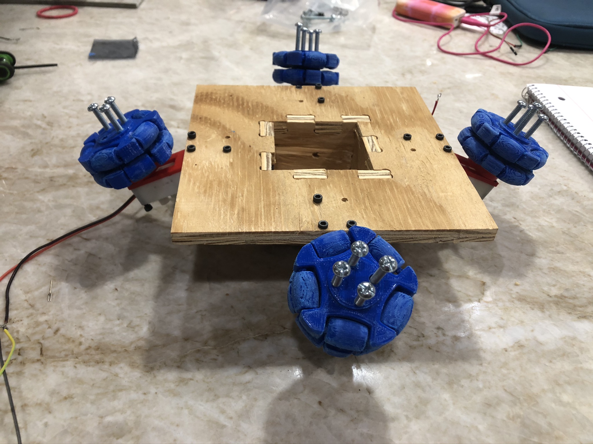
So, I switched gears to making the omnidirectional robot that functions on it’s own. My biggest issue was that I had desined the wheels to be at a 45 degree angle, and because the CNC base has a “pocket” at the bottom, the wheels don’t touch the ground. I knew I did not have time to reprint and sand all 4 wheels- especially if one messed up. Fortunately, I did have a back up plan. I knew we had some omni wheels in a bin in the back of the room. I was planning on using those IF and ONLY IF my wheels did not work. So I used those. However, I still had to redesign connectors that would connect to the new omni wheels, and make the wheels touch the ground at a 90 degree angle, not at a 45 degree one.
So the cad drawing for the wheels went from this:
To this:
(wheels not replicated in the second CAD drawing because I didn’t have time. I measured the holes in the wheels and made sure they worked with the connectors though.)
This is what I presented during the final project. After the presentation, Niel asked that I do two things.
1) Switch the arduino to a satshakit. As mentioned in the electronics section, I was unable to get a satshakit to work during the time of the presentation (I shorted many boards, kept breaking the boards, etc), so I presented my project with an arduino. Here is proof that I was able to get a functioning satshakit to work.
Hero shot:
2) I also had to finish Packaging the Product. The wires are not hidden on the project. I intended for the shell to cover them, but as mentioned, the shell did not work. So, here is a laser cut box that I made to fit snugly around the base, as well as the file.
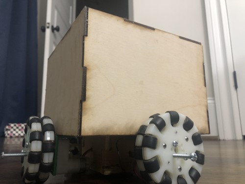
Behold! A tab box.
There are definetely things I could have done better with this project. All in all, I am happy with the project and I am happy to be finished with fabacademy because I learned a lot. It went so far beyond just learning how to use the tools in the lab, I feel like I learned a lot about time management, planning a project, executing a project, and dealing with the issues that come up along the way. I am so happy I was able to do this course, and learn all the things that I have learned in the past couple of months. I cannot wait to continue to use all these skills in the future to continue doing engineering!
Files:
Files will download (and open- of you have software to open them pre-installed(ie eagle, fusion) when clicked.)
Mega-board.sch (not ultimately used)
Mega-board.brd (not ultimately used)
Arduino simple activation code
Processing simple activation code
Fusion file- 45 degree angle wheels
Fusion file- 90 degree angle wheels
Fusion file- Box covering for the wires
Weeks breakdown:
This is a log I kept of the work I did each week for the final project, before I started actually editing this final project page.
Week01/02- Research
Most of my conclusions from research are discussed in week02, project planning week
Here I planned out all the different components of my project and what I wanted to project to do. The sources I actually used to make decisions are in that week’s documentation. Here is a link to the Conglomerate of Sources I found of people who had done this project before. This is where I got my inspiration for the project.
Week03- CAD:
I already changed my project. Originally I was using the concept with the rolling ball for bb-8 but was trying to make it more my original project> I decided it would be way cooler to do the actual bb-8 instead. I also did more research on holonomic drive systems since I decided I wanted to do this. Links to sites used are on week02’s documentation
Week04- Computer Controlled Cutting
Here we did laser cutting and vinyl cutting.
I am going to need an internal framework to support the wheels/drive system. At the time, I was not sure If I wanted to laser cut it or use computer controlled machining (CNC) this at the moment. More in depth considerations on which type of production to use for the drive system support is discussed on the week 11 section of this page.
I don’t know how I want my final product to look on the outside. I might spray paint it one solid color, then decorate it with lots of stickers. I don’t think I would make the stickers look exactly like the star war’s BB-8 design, but this is probably how I will add detail.
Week05- Electronics Design
Here I learned how to make PCB’s out of microchips. I didn’t make anything specific to my final project here, just learned the skill.
Week06- 3D scanning and printing
I did not print any objects that will be used in my final project. For the final project, I will probably 3d Print the Head, the Sphere for the Body, and the wheels. I don’t know the exact dimensions of my project (and don’t want to waste material until I know exactly what I need to print). I may either print the mecanum wheels from my CAD design, omni-wheels (see information on which drive system I chose to use, around week11) and the body sphere may look something like this.
I will probably scan the magnets I use for the head and body, and create a 3d object that fits around them. This is only if the magnets are some irregular shape/it makes sense to scan them for some other reason I haven’t considered. Otherwise, I will just measure the dimension and design an object to fit around them/hold them in place.
Week07- Electronics Production
During this week I learned how to design my own PCB board. It is like designing a circuit, but this circuit is stuck to a board and includes microcontrollers and programming. I did not design a specific PCB for my final project, but this is the week where I learned the skill.
Week08- Computer controlled machining
As discussed in the section about week04, I may either use Computer controlled machining (CNC) or computer controlled cutting (Laser cutting) for my final project’s internal drive support system. More in depth information can be found on the week11 section of this page.
Week09- Embedded Programming
This week was about programming the microcontrollers I made. Programming specific to my final project can be found in the input and outputs weeks.
Week10- Input Devices
I needed an accelerometer and a gyroscope for the self balancing portion of the robot. The explanation of what these component’s do and how I made the board/ the software to process it can be found in the week itself.
Week11- Applications and Implications
I am making a robot that moves around, so I needed motors for the drive system. I made a BLDC motor board to control motors that I will be purchasing, specifics on this type of motor, how the board will control it, the programming etc can be found in the week itself.
Week12- Output Devices
I am making a robot that moves around, so I needed motors for the drive system. I made a BLDC motor board to control motors that I will be purchasing, specifics on this type of motor, how the board will control it, the programming etc can be found in the week itself.
I didn’t discuss choosing a motor in depth during the week, so I will here.
There are many variations on holonomic drive systems. Since week 2, I had been debating how many wheels and what types I should be using for my project. The biggest question was omni wheels vs mecanum wheels, and if I chose omni-wheels, 3 wheel drive vs 4 wheel drive.
It seems that omni wheels are better at moving in all directions, but mecanum wheels are a lot more efficient and stronger when going forwards or backwards. There is also the aspect of lateral movement, but it is not as ”omni-directional” as actual omni-wheels. source. One problem with mecanum wheels is that they are slower, heavier, and bigger than their more agile omni-wheel counterpart. source.
I was originally inclined to opt for omni wheels, because I want this robot to be agile and have as full of a range of movement as possible, but I wanted to look at other people’s bb8 interpretations to see which one of the wheels worked best inside the spherical frame that the holonomic wheel drive will be propelling. I had found a patent earlier with original designs for bb8, and upon finding a website that analyzed the patent I realized that it uses omni wheels. So I think I will opt for omni wheels.
I’m still debating between using the stabler and simpler to use 3 omni wheel drive configuration versus the faster and more efficient 4 omni wheel configuration. 3 wheels are cheaper so I will probably use those. source.
Motors:
A lot of DIY sites that I had been originally looking at use Stepper motors for omnidirectional robots. I assumed I would have to use those, however, after watching the output video and learning the differences I wasn’t sure why one would use a stepper motor instead of a DC motor to control a robot’s drive. I did some research,
Selecting the specific motor:
How to choose the right motors for your project Torque, biggest consideration for choosing motors Connecting the motor and the wheel: How to connect an omni wheel shaft and a motor
C Code and programming: bitwise programming attiny’s with arduino as isp’s
Many, Many links from research: Implementing mecanum drive presentation
Steper motor to arduino tutorial
Week13-
Here I designed an interface that communicates with my BLDC motor. It interfaces with Arduino’s serial output, so I can control the RPM of the motor from a graphical user interface.
The software wasn’t designed so I did not make an application that utilized it, but eventually I will need software that moves the wheels in different directions, and an application that can control that. My Drive system is holonomic, so the programming for that will look very different from a typical 4 wheel drive robot.
Week15-
Here I worked on the networks system needed for my robot. I used a bluetoth module to communicate between a processing app on my PC and the satshakit/ motor driver board that controlled the motors of the robot.