3. Computer Aided design
This week we were assigned to create a model of our project on as many programs as we could.
Fusion 360
To begin, I wanted to design my first model on Fusion360. Yikes. The first time I used Fusion was about a year and a half ago, and it was also the last time. I had not touched the program since then until now. Needless to say, I was very confused and lost, but thankfully the head of our lab node provided extensive tutorials from the Autodesk website that allowed me to practice and brush the cobwebs away a bit. I watched the tutorials under Design: Sketch, completed the activity ‘Creating sketches and converting them into 3D features’, and began the ‘Construction geometry and constraints tutorial for beginners’ activity under the same dropdown.
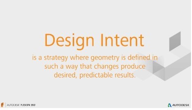
 The video tutorials refreshed my memory of Fusion and also taught me a new term, Design Intent, which I now know means “a strategy where geometry is defined in such a way that changes to produce desired, predictable results.” By understanding this, it not only allows me to modify my creations in any way I want, but also lets me understand how design on Fusion effectively and efficiently.
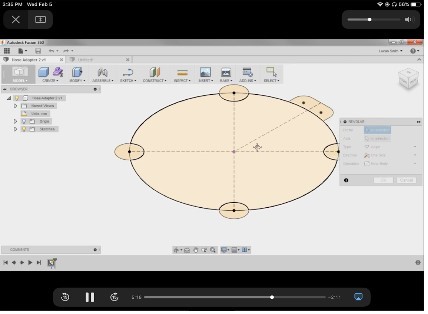
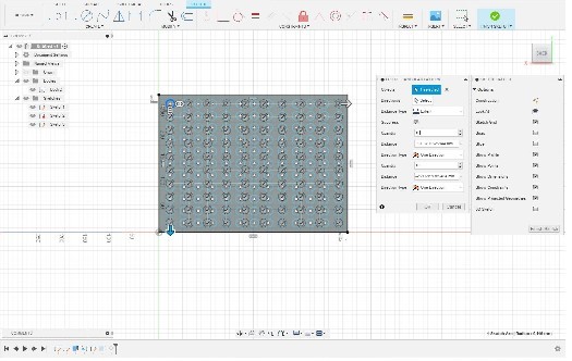
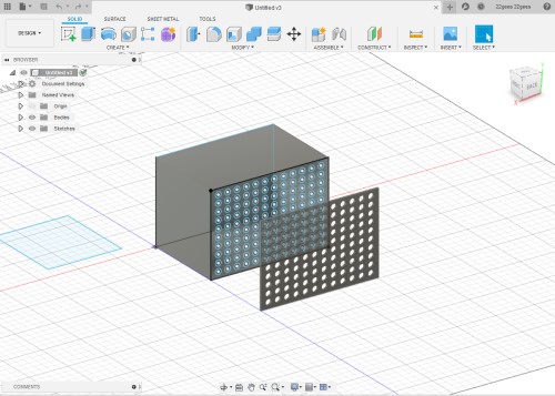
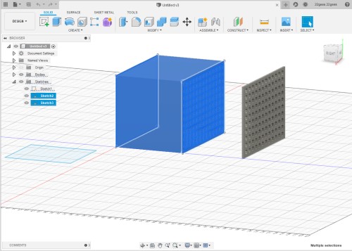
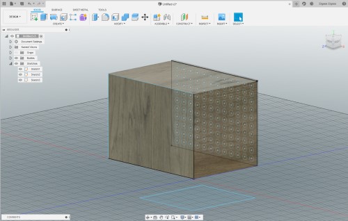
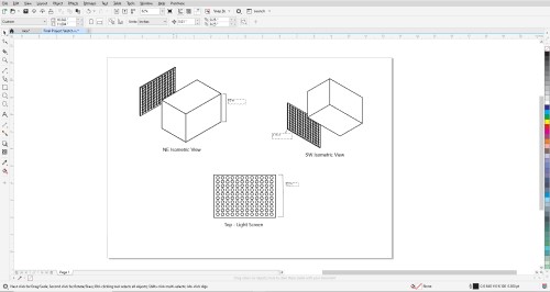
To start off my sketch, I drew a rectangle and made the width 400 and the length 300. With the help of my teacher, he briefed me on how to extrude and shell the box that we eventually made. He also showed me some easy short cuts to get to tools I wanted like ‘E’ for extrude. From the tutorials, I had learned how to align circles in an even circular pattern. For this sketch, to create the screen, I took the top face of the box and moved it away from the rest of the cube. From there, I made one circle, and using the ‘Rectangular Pattern’ tool, I added a quantity of 10 more.
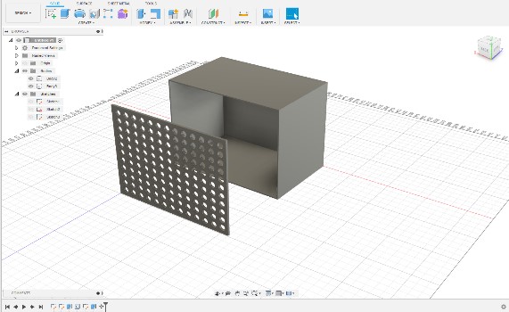
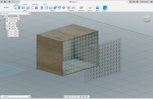
Wanting to make the model look more realistic, I selected the body of the box without the screen and added materials to it by selecting ‘Modify’ –> ‘Physical Materials.’ I want to make the box out of somesort of wood, most likely plywood, but the plywood did not show up when I dragged it to the body of my design, so I just used regular wood as a reference instead. I plan to make the screen clear, so once I had altered the box to be made out of wood, I dragged the acrylic material to the screen. I chose acrylic because it not only is it clear, but I will be able to laser cut it as well. Once I had done that, I moved the screen back to the body with the ‘Move’ tool.

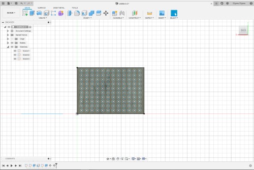
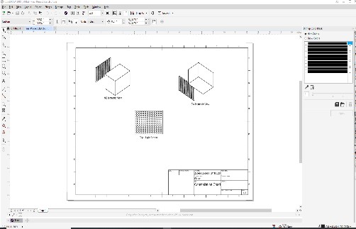
I then switched workbenches on Fusion and went from the ‘Design’ page to the ‘Drawing’ page. I had never used this workbench before, so I was excited to try it out and experiment a bit. Overall, I liked how the sketches looked. I added subtitles describing the view of each sketch.

My Fusion File:
Inkscape
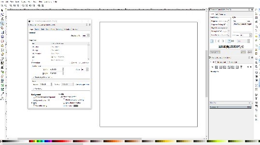
This is another program that I had not used in a very long time. I was basically a beginner. I began by editing my page size in the ‘Document Settings’ to 30 in x 30 in because those were the measurements that I had always used in my previous classes. Then, I went to the ‘Grid’ tab and added a where there was a line every 2 inches.

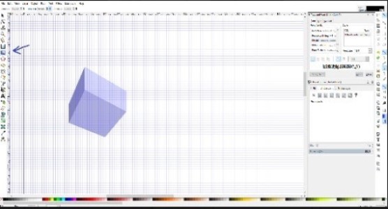
I had no idea how I was going to go about designing the box on Inkscape, so I decided to simply start drawing. Firstly sketching a 2D rectangle, I filled it with a random color and looked around the program for anything similar to the ‘extrude’ feature in Fusion 360. Very quickly, I found what I thought to be a better alternative: the 3D cube feature. I left my poor rectangle drawing on its own and sketched a cube with no specific dimensions on the page.
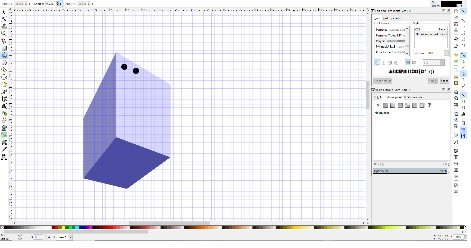
I then drew two circles in the upper left hand corner of one face of the cube. Using the ‘combine’ option, I combined the two circles, essentially grouping them together. Then, using the ‘group’ tool, I grouped cirles and the cube together.
Corel Draw
I have used Corel Draw in the past, but I had always worked inside of the program and had never imported something from another program into it. On the sketch from Fusion360, I clicked “PDF Output” to export my drawing.
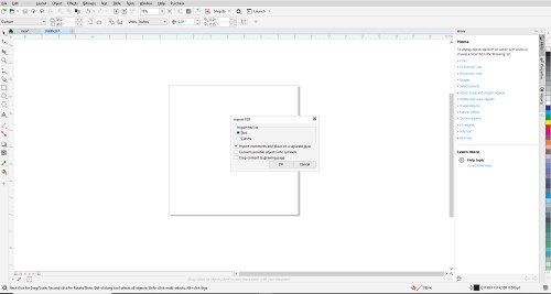
I edited the size of the page be 30 in by 30 in because, when it loaded, the page was very narrow and the sketch was not loading into it. I kept the subtitles that I had made in Fusion, so I could easily differentiate the two Isometric views. Finally, I looked to see if all of the corners were actually connected, and they were, so I left them as is.
Here are my Inkscape and Corel files: Click Me