5. Electronics production
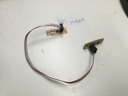
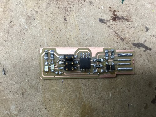
This week’s individual assignement was to make an in-circuit programmer by milling and stuffing the PCB and then test it. For the group project, we were required to characterize the design rules for your PCB production process.
Making the Programmer
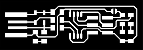
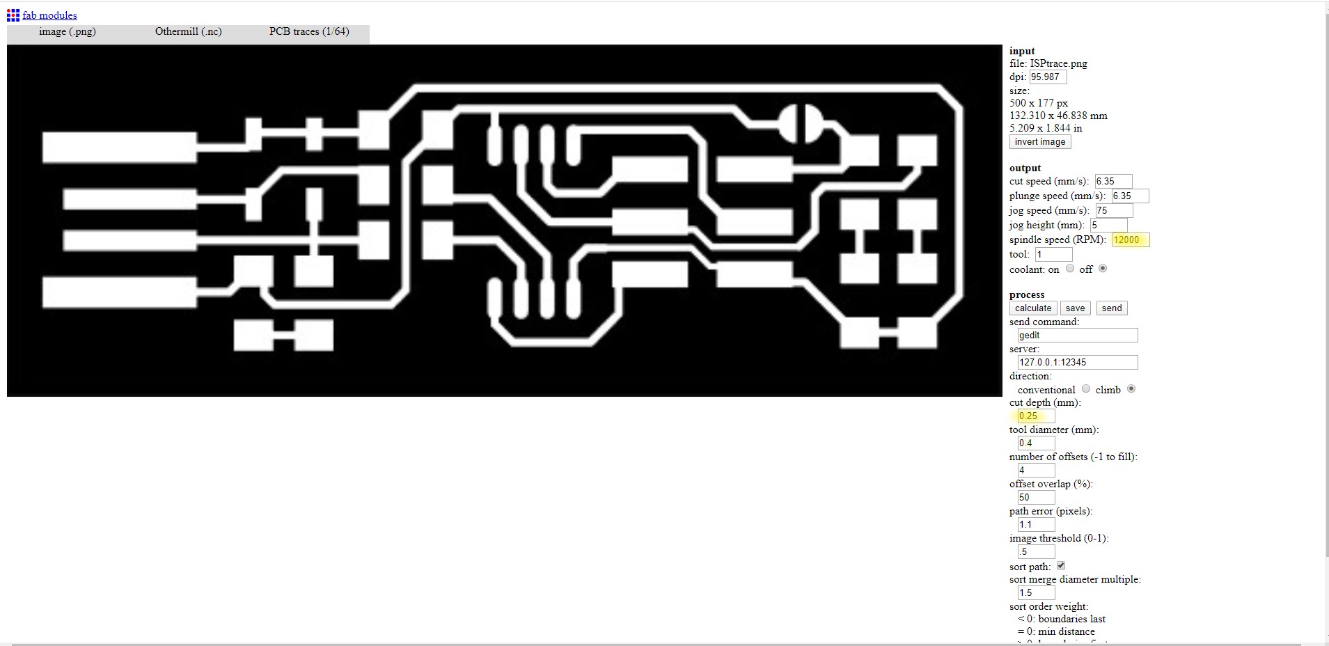
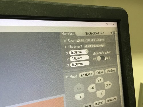
I got the trace and outline from Brian’s tutorial and then imported them as PNG files into Fab Modules. I edited the tool bit’s details by looking at this chart.
Milling
Before milling the machine, I had to prep it. I used a dry paint brush to brush extra particles from previous runs and then vacuumed them out. Once the machine was fully clean, I used a piece of blue shop towel and about two drops of rubbing alcohol to clean off the machine bed. The machine was now ready.
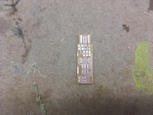
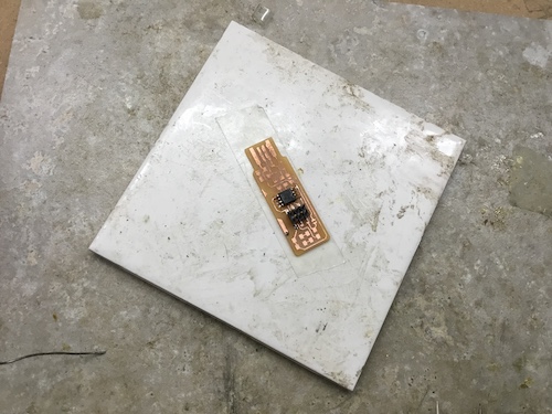
In our lab, we have a bucket of copper rectangles to be used for milling, so I selected one of those and measured it with a caliber. I collected the measurements and entered them into the milling software, Bantam Tools. From there, I uploaded two files for the board- one for the outside which would actually cut through and one for the traces. I used a 1/32” bit for the outside and a 1/64” bit for the traces. Then, I stuck the copper rectangle onto the bed using nitto tape.
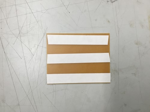
In order to mill the programmer, there were many steps I needed to complete. First and foremost, after entering in my copper board measurements and uploading my files, I needed to put the bit into the machine. There are two wrenches that come with the machine that are made for this specifically, but I prefer to use my hands because I feel that I have more control this way. After inserting the 1/64” bit, I held the silver part of the bit holder with my thumb and forefinger on my right hand and also held the bit with my middle finger on the same hand. I spun the nut (twisty black piece) with my left hand to tighten it. I placed my copper to the machine bed which I attached with nitto tape.
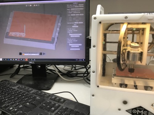
Once the bit was tightly secured, I transfered my attention to the softwawre and selected ‘locate tools.’ By doing this, it allows the machine to know what tool is in use, so it can identify what it needs to do at which part in the milling process. Once I had my tool located, I selected ‘Probe material thickness.’ This was also crucial because by knowing how far down the copper was to the bit, it would be able to cut through the copper without hitting the bed.
I selected which bit would be used for each file, re-homed the bed, loaded it, and milled the traces. When it was done, I changed out the bit to the 1/32” and clicked ‘locate tools’ again. I clicked go and when it was finished, I had my board!
Suface Mount Soldering
Milling the board was only the beginning, surface mount soldering the pieces on was a bigger challenge. I used Brian’s tutorial to figure out the placement of all of the pieces.
I used two tweezers to solder: one that looked kind of like a flat head screw driver and one regular pair. The flathead set was to align the pieces in the general place and the regular pair was to place them in the precise spot. I placed a small dot of solder on one of the pads that the piece that I was soldering was supposed to go and then put the piece on it and waited for it to cool. This way, the pieces would be easier to solder because the piece would already be secured.
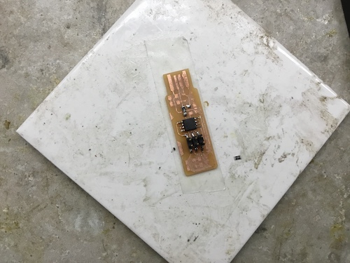
Following his in depth instructions, I was able to get the board working. I did make quite a few mistakes along the way, though. I realized halfway through soldering that I had attached my diodes on the wrong way.
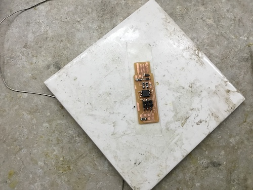
I fixed this by taking off the solder with a copper wick and went on to place all of my other pieces down.
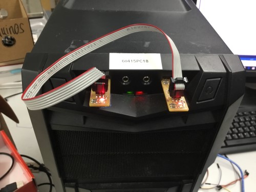
In order to allow my board to fit more smoothily into the USB port, I added electrical tape at the back of it.
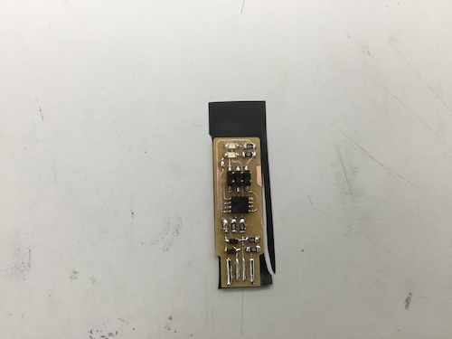
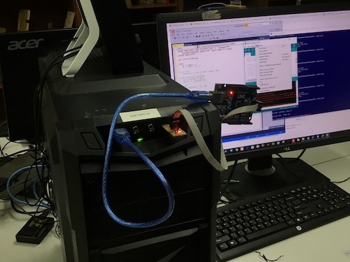
To test if the connections worked, I did not plug my USB straight into the computer. Instead, I used a dongle to avoid messing with anything on the computer or potentially somehow frying the board. The light flashed red which showed that it worked.
Programming
This part was the most challenging of the week by far. I am taking AP Computer Science Principles this year, so I have a light background in how to read code, but programming is a different challenge. In the past, I programmed a neopixel ring and a mic amp, so that the neopixel flashed with the sound of the ukulele they were encased in. However, I had never gone further than that- programming-wise.
I started by downloading all the programs I would need including: Atmel Studio, AVRDude, the AVR GNU toolchain, GNU Make, Zadig, and the firmware source code.
There is a tutorial on the next steps I followed Here.
I used my teacher’s programmer to make my own board a programmer.
What I did:
-
Because I had installed all the programs I needed, all that was left, in this regard, was to extract the files. I started by extracting the files from the AVR toolchain by Microchip and put them into a folder called “Program Files”.
-
I did the same with AVR Dude. I unzipped the file, clicked ‘Extract All,’ and then placed them into “Program Files.”
-
I repeated #2 again except with GNU Make.
-
Hitting the Windows key in the search bar, I entered in ‘Environment Variables’. After opening it up, I let it vibe out on the side and went into File Explorer.
-
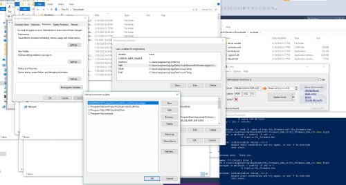
Once File Explorer was opened, I located my AVR toolchain, found the “bin” folder and copied the directory path. I did this twice more - 1x for GNU Make and another for AVRDude.
-
In the Environment Variables, I selected “Path” and pasted in the three paths I had just copied one by one.
C:\Program Files\avr8-gnu-toolchain-win32_x86\bin
C:\Program Files\GnuWin32\bin
C:\Program Files\avrdude
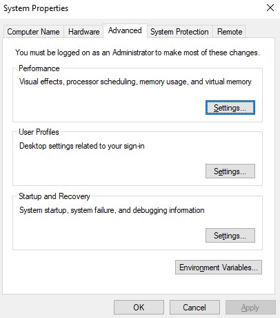
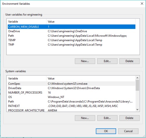
I clicked OK on all of the newly opened tabs (System properties, Environment Variables, and Path)
I plugged my USB into a dongle, so that I would not have the possibility of messing anything up by plugging my programmer directly into the computer.
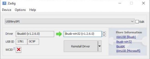
I already had Zadig downloaded, so I clicked Options –> List all devices –> USBTinySPI. I made sure that in the ‘Driver’ column it read
libusb0 (v1.2.6.0) --> libusb-win32 (v1.2.6.0)
For the next steps, there were many ways to go about it, but I chose to use Windows Powershell, as it was easier to get GNU Make to run with it. I learned the commands ‘cd’ - change directory, dir - show directory, make ___ - more specific commands.
In Powershell…
- I typed in ‘cd’ (change directory) and switched the directory to Program Files. When done, it looked like this:
cd C:\Program Files
-
all that was left to do was to physically make the board a programmer, so I entered:
make flashmake fusemake rstdisbl -
it should have been that easy…but it wasn’t. At first, it alerted me that I was doing everything wrong in red text, but I figured out that it was because I had made typos when entering in my directory.
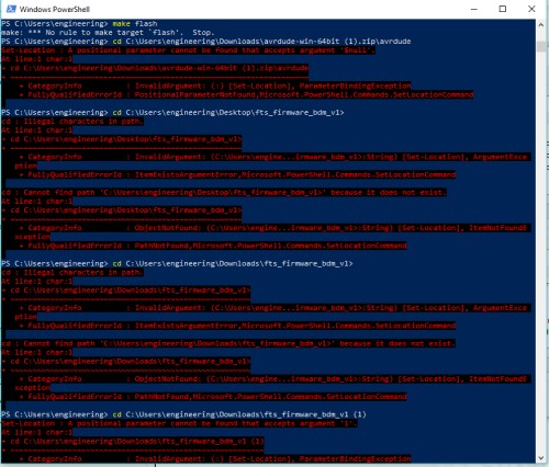
- I corrected those errors, but it still wasn’t working. However, it was not in red text. It was telling me that it could not find what I wanted it to, so I, wanting to avoid any further issues, extracted my files again and placed them in the exact same folder. I also made sure to push my USB into the dongle a bit more, just in case that was the issue.
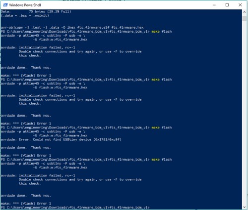
- It seemed to work, and so I again entered in:
make flashmake fusemake rstdisbl
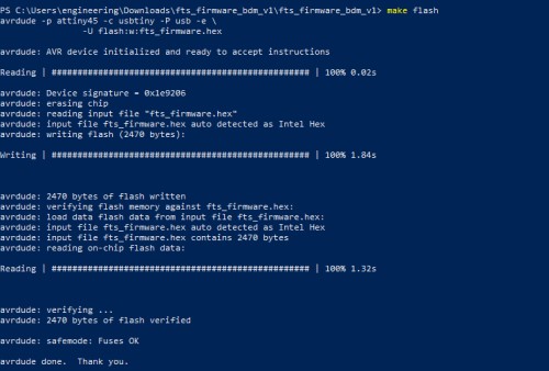
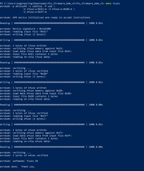
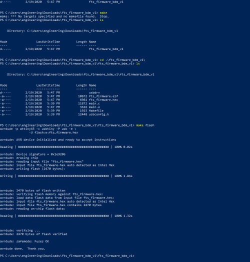
Finally, after I had programmed the board, I split the solder bridge.
Blinking an Arduino
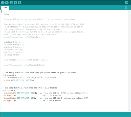
To test if my programmer worked, I decided to use my programmer to blink and LED on an arduino. I used the ‘Blink’ example code provided by Arduino (Examples –> Basic –> Blink).
![]()
When everything was set up, I clicked on the ‘Tools’ drop down and hovered over ‘Programmer,’ which then allowed me to select ‘USBTinyISP.’ I made sure that the ‘COM’ port I was using aligned, I chose File –> Preferences. Instead of clicking upload like I normally would, I altered the preferences to ‘show verbose output’ during output. The light successfully blinked after I clicked ‘OK.’ I tried to upload the code regularly beforehand, but it did not go through and came up with an error message. I did not have the programmer fully pushed into the port, and I also had not changed the preference settings then.
Group Assignment
This week we were required to characterize the design rules for your PCB production process. We decided to use Eagle as our program to do this. None of us knew much about Eagle, so we each referenced multiple sources. I used this website. My contribution to the group project this week consisted of defining some of the new terms we were asked to research and setting up the CNC machine for milling. I also briefly played around with Eagle, but ended up reverting back to Fab Modules to create the board. My group members worked more with this, as shown on our group site.