7. Electronics design
Our assignment this week: - use the test equipment in your lab to observe the operation of a microcontroller circuit board - individual project: redraw an echo hello-world board, add (at least) a button and LED (with current-limiting resistor) check the design rules, make it, and test it
Designing in EAGLE + Milling
For this week, I chose to use the Attiny412 microchip. I followed this tutorial very carefully to figure out what to do. I do NOT recommend this. This tutorial was helpful in the way that it showed me certain tools to use, tips to know, etc.. However, following it as closely as I did screwed me up and caused me to make many mistakes that I would not have made had I simply followed the tutorial loosely and filled in the blanks myself.
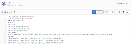
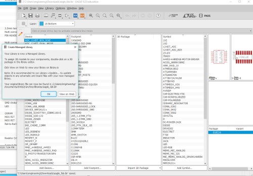
I first downloaded the libraries eagle_fab and fab_new, which my teacher provided to get the components I wanted. Once they were ready, I added in the parts that I needed by looking at both the blink and echo board.
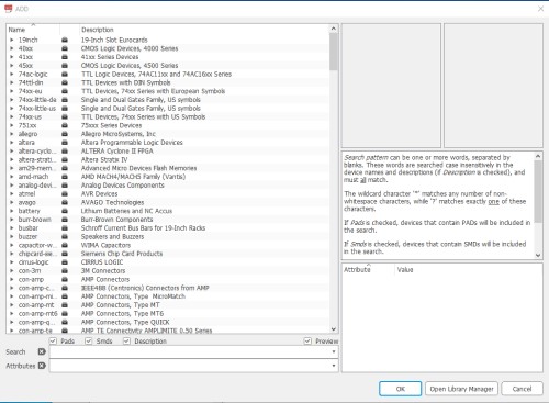
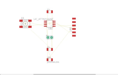
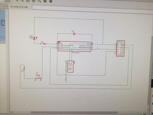
In Eagle, I created a new project schematic and got going. I added in the components I needed and, from there, I got to working on connecting them with the nets. This was the first time I had ever used Eagle, so to say it was a struggle is an understatement. Before using the program, I watched Part 1 and Part 2 of this Eagle tutorial. However, I still did not really understand how to use it, to be honest.
net tool:

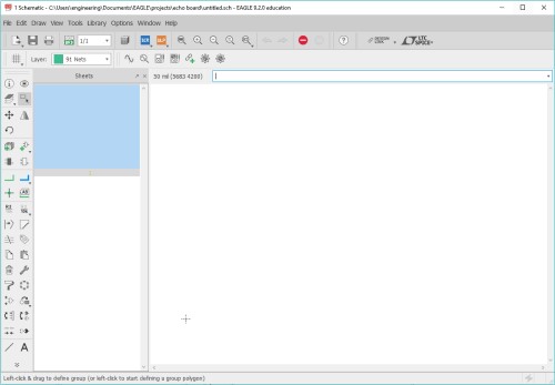
I decided to just jump in and figure things out as I went. Once I had all of my parts connected and facing the right directions, I changed to the board layout from schematic.
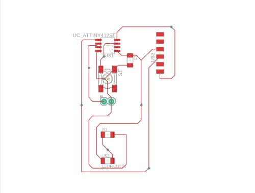
In the board layout, I had to route the components together. This caused so many issues, whew. I decided to manually connect them together, which in turn caused me to make multiple prototypes, but they looked better with each try.
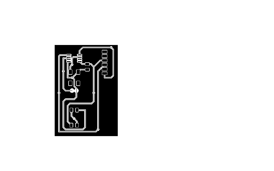
Here is the black and white image from the CAM processor:
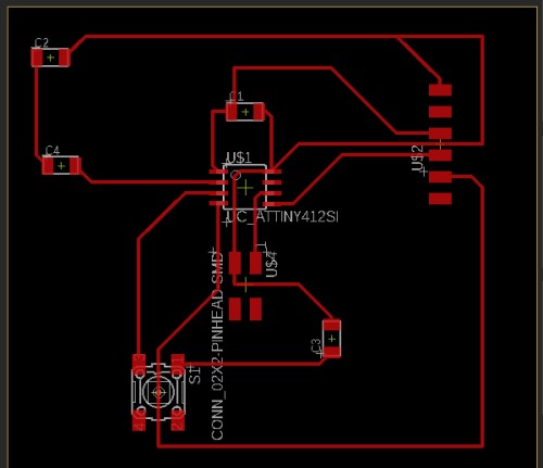
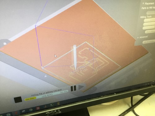
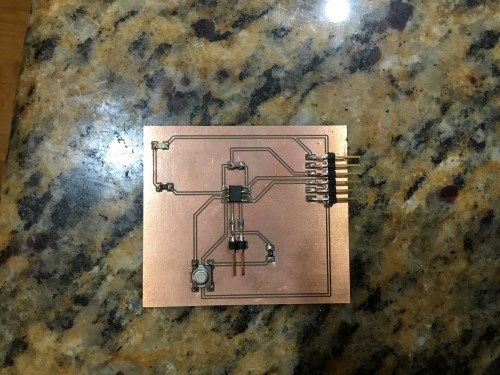
My final board layout looked like this:
I had some issues with creating a milling my traces where the pads of the components that I would use simply wouldn’t work. They would not show up on Bantam tools which caused a boatload of issues for me. At first, I thought it was something I had did or the physical componets themselves. I copied and pasted my schematic into a new project and replaced the components that refused to show up with the same parts, so the new schematic ended up looking like a carbon copy of the first.
That did not work. The pads for the LED and both resistors refused to show up.
After sitting at my computer being completely frustrated for about 10 minutes, I came up with a plan: what if I replaced the ‘no-show’ components with the one that did? Every time I had uploaded my board to Bantam Tools, the capacitor showed up. With this in mind, I replaced every resistor and the LED with the capacitor in the schematic.

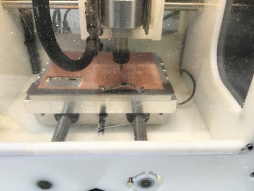
Milling the board:
Soldering
I gathered the materials I would need (components, new soldering tip, solder, etc.) and got to work. I first soldered the microchip and worked around the board from there.
My first soldering job was extremely messy which caused me to have many short circuits. I did not know this at the time before my teacher pointed it out to me. However, this was after I tried to program it, and the programmer and the attiny412 chip I used almost overheated.
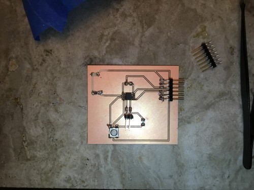
It was better for me to just make a new board altogether, so I did. I milled the same board and got to work again, but this time all the more carefully.
Programming
I downloaded the Arduino library for my Attiny412 from this GitHub site.
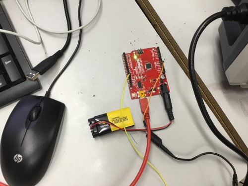
I connected my board to an ardiuno to program it, and I followed this engineers instructions from his site.
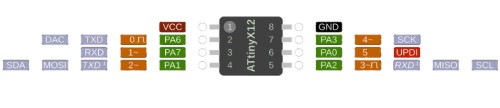
Once that was done, I used the example button code by Arduino and changed the pins using this reference:
I then uploaded this code once I knew the button code worked and pulled up the serial monitor, so that it would echo. Instead of my board being attached to the arduino, I plugged the FTDI into it, so that it would run the echo code.
#define F_CPU 20000000

#include <avr/delay.h>

#include <avr/io.h>


uint8_t counter;


void setup() {

   PORTA.DIRCLR |= PIN7_bm;           //Set PA7 to input

   PORTA.PIN7CTRL |= PORT_PULLUPEN_bm;  //Set pullup resistor on PA7

   PORTA.DIRSET |= PIN6_bm;           //Set PA6 as output

}


void loop() {


  if(~PORTA.IN & PIN7_bm){  //check to see if PA7 is pulled low

     while(~PORTA.IN & PIN7_bm){ //wait until PA7 returns high

      _delay_ms(5);

      counter++;

      if(counter >= 5){

        PORTA.OUT |= PIN6_bm; //set PA6 LOW

        _delay_ms(1000);

        PORTA.OUT &= ~PIN6_bm; //set PA6 HIGH

      }

     }

  }

}
It worked!
Group Project
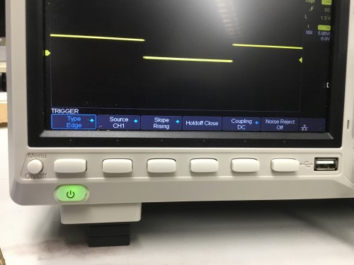
To kick off this week, I learned how to callibrate an oscilloscope by watching this video and learned about them through this site.
To test our probe, we used the built-in frequency generator and connected our probe’s ground clip to the ground and the probe tip to the signal output. Signal waves began to show up on the oscilloscope’s screen, however they were upturned a bit on the corners. To correct this, we used a tiny flat-headed screw driver to compensate our probe.
My files: