9. Embedded programming
The individual assignment for this week was to read a microcontroller data sheet, program your board to do something with as many different programming languages, and to program as many environments as possible. For the group assignment we had to: compare the performance and development workflows for other architectures.
Group Assignment
For our group assignment, we chose to figure out how to use Raspberry Pi. I, and most of my other fab classmates, had never used Raspberry Pi prior to this nor really knew what it was. We decided to compare AVR (arduinos and attinies) to Raspberry Pi. According to this website, Raspberry Pi is a low cost, credit-card sized computer that plugs into a computer monitor or TV, and uses a standard keyboard and mouse. Raspberry Pi has an ARMv6 700 MHz single-core processor, a VideoCore IV GPU and 512MB of RAM. it uses an SD card for its operating system and data storage. The Raspberry Pi officially supports Raspbian, a lightweight linux OS based on Debian.
We started by following this tutorial to set it up and start using the interface.
These are the components of the Raspberry Pi.
We learned that the Raspberry Pi has much more memory than the AVR chips.
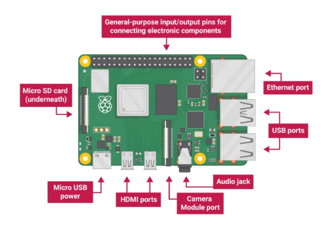
- USB ports — these are used to connect a mouse and keyboard. You can also connect other components, such as a USB drive.
- SD card slot — you can slot the SD card in here. This is where the operating system software and your files are stored.
- Ethernet port — this is used to connect Raspberry Pi to a network with a cable. Raspberry Pi can also connect to a network via wireless LAN.
- Audio jack — you can connect headphones or speakers here.
- HDMI port — this is where you connect the monitor (or projector) that you are using to display the output from the Raspberry Pi. If your monitor has speakers, you can also use them to hear sound.
- Micro USB power connector — this is where you connect a power supply. You should always do this last, after you have connected all your other components.
- GPIO ports — these allow you to connect electronic components such as LEDs and buttons to Raspberry Pi.
Datasheet
I had no idea how to read a datasheet, so I used this Sparkfun tutorial which I retrieved from alumna Maxine Tan’s site. This was very helpful because it was clear and concise and provided a lot of information on how to find information on a datasheet. The datasheet also provided knowledge on the general structure of the microcontroller and what ports went to what.
TinkerCircuits
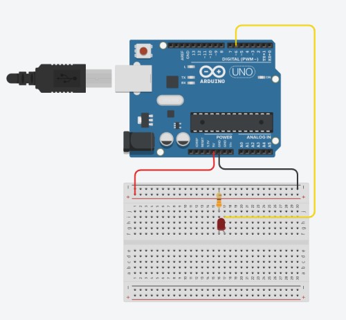
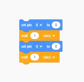
For my C code, I set up a basic circuit for a blink code. I was inspired by Fab Academy graduate, Will Knight to do this because it was easy to map out visually.
Arduino
I used Arduino IDE to program the board. I did not have a programmer with me, so I watched this youtube video, referenced this website for the set up, and this tutorial in order to figure out how to use my arduino as a programmer.
Once everything was sorted, I had to set up the board. Honestly, I did not know where to begin, but I remembered I had talked to Dr. Harris before during the electronic design week about this exact thing. I reviewed the notes and pictures I had taken of the set up then and applied them to this week.
I learned that I had to add a capacitor to block the current flowing between the ground and the pins, so that the chip did not reset itself. I made sure that the board selected was the Attiny412 and that the programmer selected was the jtag2updi aka the arduino which I had just made into a programmer. This tutorial also helped me change my arduiono into a programmer.
In preferences, I added this link that I got from the tutorial:

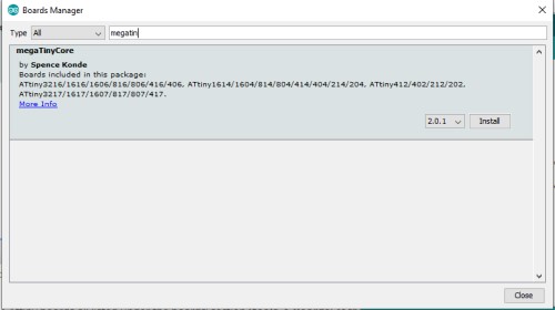
Next, in the boards manager, I entered “megaTinyCore” and installed the one by Spencer Konde.
After that was installed, I checked my boards and saw that I had the Attiny412 there as long as other Atmel Tinys. I then downloaded this folder provided and set up the arduino to connect to my microcontroller. In arduino, I made sure that the board was the Attiny412 and that the programmer was the one that I had just downloaded, the jtag2updi.
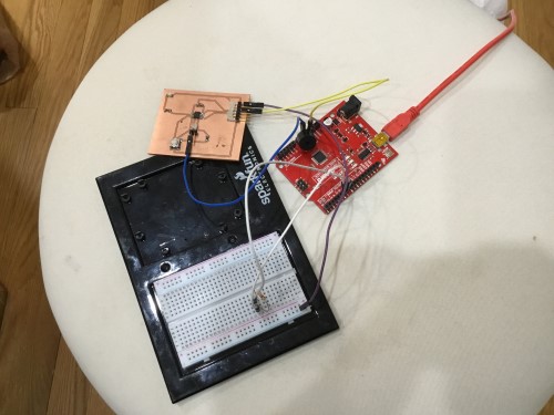
Here was my set up:
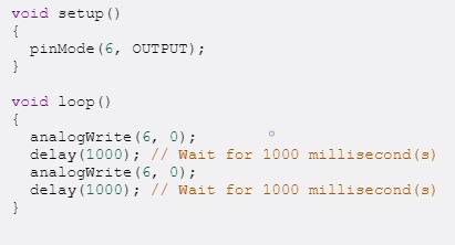
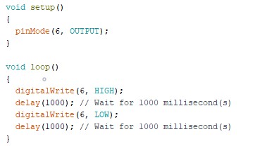
I used the basic blink code to blink the LED.
Atmel then Python
I wanted to use Atmel as another way to code my board. The downloading process was extremely slow which I just connected with the fact that there was low disk space on my computer. After clearing out some files, the downloading process was still slow. I just let it be and take 4000 years to download.
I planned to use C bitshifting to blink my LED. After downloading the program, I went in and created a new project, making sure I had selected the Attiny412 as my device. This was when I realized that I did not have a physical programmer with me to hook up to my board. I thought about searching for a way to use the arduino, but instead I opted out of that.
I still wanted to learn the basics of Atmel a bit more, so I referenced Maxine Tan’ssite to see how she went about using the program. She used an Attiny44 for this week and also her FabTiny ISP to program. I also watched this video and scanned through this data file to learn some basics about Atmel itself and how to use the program in general.
To fufill the assignment of using multiple programs, I followed this tutorial which was written by one of my Fab teachers, Dr. Harris.
The first step was to make the arduino into a progammer, which I had already done, so that was one step down. Following his directions, he instructed to download this operating system.
Once I had done that, I downloaded Python 3. Then, I installed “PIP 3” like he said to. After that, I installed the dependencies for pyUPDI using the line pip3 install intelhex pylint pyserial I downloaded and unzipped the project for the pyUPDI using the link he provided.
- In Atmel: new project and then find the microchip you’re using.
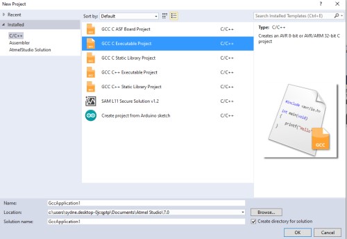

- After selecting the board, I was brought to this page.
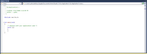
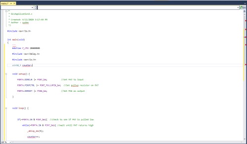
I did not really know where to go from here, but after talking to some of my fab classmates to see how they went about the week, I used the code from the Electronic Design week that our teacher had made and pasted it into Atmel.
define F_CPU 20000000

include <avr/delay.h>

include <avr/io.h>

uint8_t counter;

void setup() {

   PORTA.DIRCLR |= PIN7_bm;           //Set PA7 to input

   PORTA.PIN7CTRL |= PORT_PULLUPEN_bm;  //Set pullup resistor on PA7

   PORTA.DIRSET |= PIN6_bm;           //Set PA6 as output

}

void loop() {

  if(~PORTA.IN & PIN7_bm){  //check to see if PA7 is pulled low

     while(~PORTA.IN & PIN7_bm){ //wait until PA7 returns high

      _delay_ms(5);

      counter++;

      if(counter >= 5){

        PORTA.OUT |= PIN6_bm; //set PA6 LOW

        _delay_ms(1000);

        PORTA.OUT &= ~PIN6_bm; //set PA6 HIGH

      }

     }

  }
Further following his tutorial, I connected a FTDI chip which I had recieved from my lab to my board. The FTDI chip was 5V whereas Dr. Harris said to use a 3.3V. This was not that big of an issue, just another variable in the eventual set up. Opening up the Arduino Blink file, I made the necessary changes to the pin numbers, following his directions. I went into the pyUPDI folder, opened a terminal, and downloaded my board using the command he provided sudo python3 pyupdi.py -d tiny412 -c /dev/ttyUSB0 -b 115200 -f Blink.ino.hex -v (path to FTDI port: /dev/ttyUSB file: Blink.ino.hex). The light blinked for a bit but then turned off.
I took this as it working so I was happy!
Group Assignment
Look through our group work for this week here!
Takeaways
I learned a lot this week about electronics, and although I am still confused about how all of this works, I hope that future assignments will help provide some clarity.