| Material | Cost |
|---|---|
| PLA Filament | 0.07 JD/gram |
| servo motor | 5 JD |
| Acrylic | 10 JD |
| atmega328p | 0.55 JD |
| Resistors | 0.5 JD |
| Capacitorss | 0.1 JD |
| PCB material | 10 JD |
| 16MHZ crystal | 0.15 JD |
| LED | 0.05 JD |
| Wires | - |
| Batteries | 3 JD |
| Voltage Regulator | 2 JD |
| Pin Headers | - |
1-3D-Desined Cat Feeder Model.
Stand
It is the part that holds servo motor
.PNG)
Food outlet
It is the part that prevents and allows food to go out to the pet
.PNG)
.PNG)
.PNG.png)
Food container
It is the part that stores food as a container
.PNG)
.PNG)
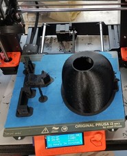
3D printing
I printed the finished 3D design on the Ultimaker 2+
I cut the food outlet in half and made a male piece and a female piece for me to print the machine without support materials.
.png)
.png)
.jpg)
I will attach the design file to the following link:
1-2D-Desined Cat Feeder Model.
At this stage I will design the machine's exterior structure
.PNG)
.PNG)
.PNG)
I designed small rectangles on the design in order to bend the acrylic sheet after finishing the cutting.
.png)
I will attach the design file to the following link:
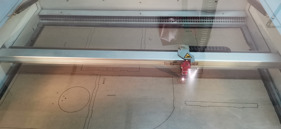
computer-controlled cutting
After finishing the design with Fusion 360, I will cut it using a trotec laser cutter, and using the trotec JobControl program of the machine, I will cut the acrylic sheet, after choosing the color of the cutting which is RGB, using CorelDRAW.
.jpg)
Using Corel Draw software I prepared the image for cutting after that I cut the design on 3mm acrylic board.
.jpg)
The result was like this
.jpg)
Circuit designing done in Eagle
I will be designing my board using the software I did Eagle just like in the design week but using anAtmega 328P processor.
To making of Echo Hello M needs:
first downloaded the library of the components for eagle.
And needs components:
| components | Number |
|---|---|
| Button | 1 |
| Atmega328p | 1 |
| Resistors | 3 |
| Capacitorss | 5 |
| 16MHZ crystal | 1 |
| LED | 1 |
| Voltage Regulator | 1 |
| Pin Headers | 1-2x4 & 1-3x1 |
| AVR Isp | 1 |
I connect the pins of the microcontroller to labels ,and this labels connect them to other components .
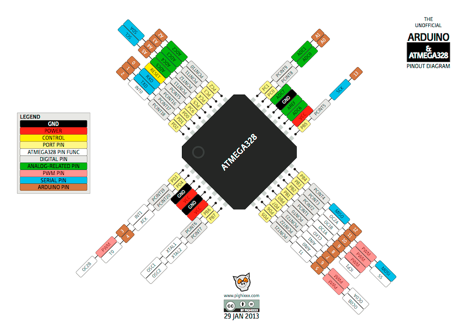
After I read the data sheet of the microcontroller Atmega328P to connect the components correctly.
A voltage regulator generates a fixed output voltage of a preset magnitude that remains constant regardless of changes to its input voltage or load conditions.
.PNG)
I added a reset button and added an LED , the LED lights up when the reset button is pressed
.PNG)
.PNG)
The crystal I used is the 16MHz (To provide a stable clock signal for digital integrated circuits, working on stable frequencies for broadcasting transmitters and receivers.)
.PNG)
I added Pin Headers to components I will added thim in my project.
.PNG)
.PNG)
ISP or In System Programming is the best way to program AVR microcontrollers as it allows them to be programmed in circuit. This is easier for development, production and most importantly, for updating the firmware later in the field. The tool used for this is an AVR ISP.
.PNG)
I also added other capacitors with values of -100nF, 1uF ,10uF- and connected to the VCC and the GND.
A capacitor is a device that stores electrical energy in an electric field. A capacitor is a component designed to add capacitance to a circuit.
.PNG)
This is the circuit design Schematics:
.png)
by using settings of Drc which is:
.png)
.png)
After completing the design, I will click on the Layers menu and hide all layers except for the Pad, Top
.png)
From the File option, choose Export, Image, and choose Monochrome ,resolution 1500 ,Area Full, And I do that for the outside cut frame.

Electronics Production
For this week, I will be producing what I designed for the project in FabLab.
And because of the (Corona) crisis we are going through, this will prevent us from doing our job to the fullest.
But in Electronics production week, I'm going to do what I did in that week.
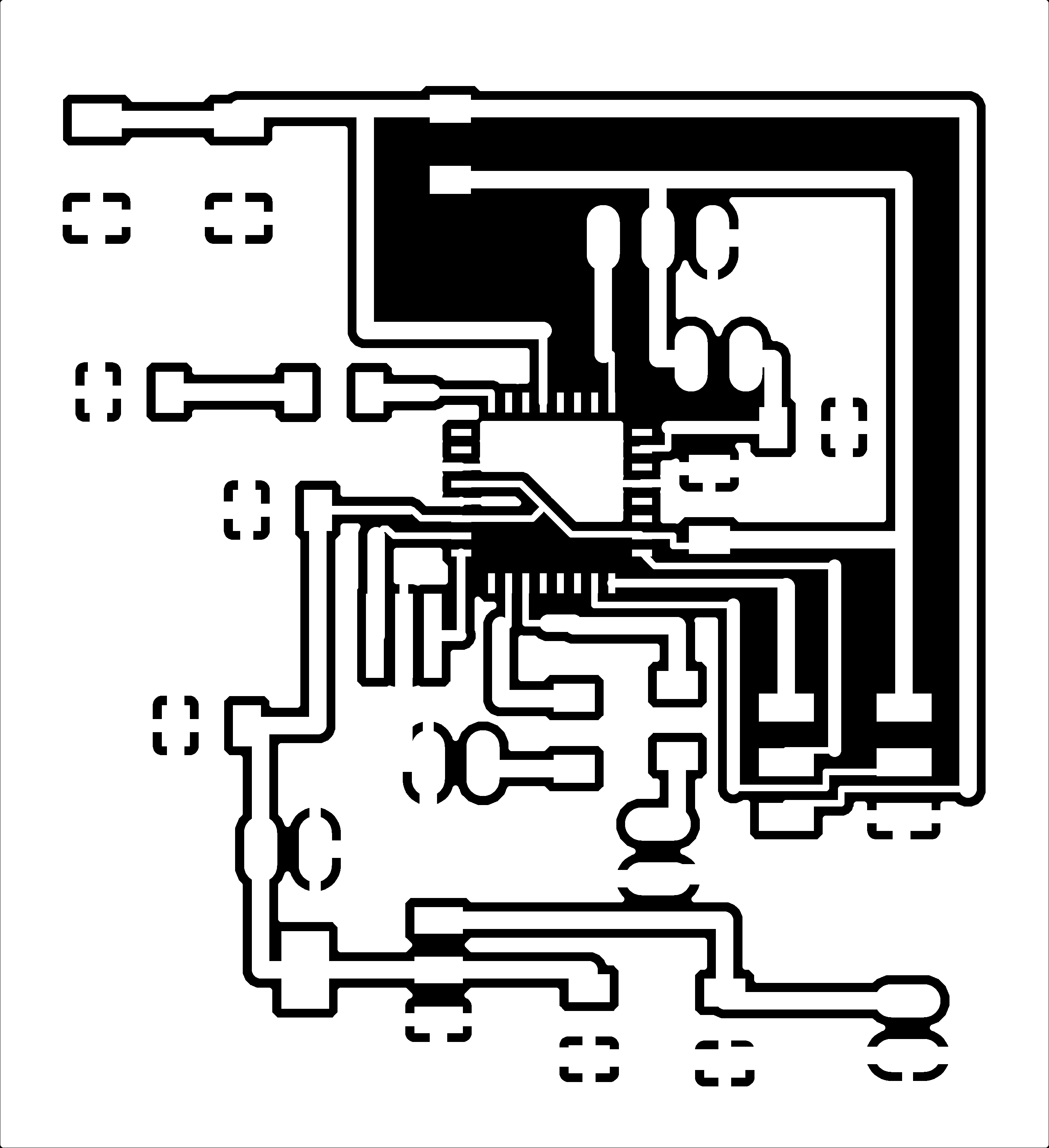
Milling the board and Roland SRM-20
The first step to producing a PCB is design PCB , I have been designed before.
The board I will milling it ,is shown in the image.
First, to convert the image into a gcode for the machine to recognize it, we have to go to a site FabModules
After entering the site, choose the image, then select the image you designed using the Eagle program, then choose the type of Roland mill machine, then choose the type of milling traces, which is 1/64
.PNG)
Speed: 1mm/s I need it slow so do not break the Milling Bit.
x0,y0,z0 because I will reset them using Vpanel which interface to the machine
Cut Depth: this was set to 0.1
Number of offset:this was set to 4 to make soldering easier
.PNG)
.PNG)
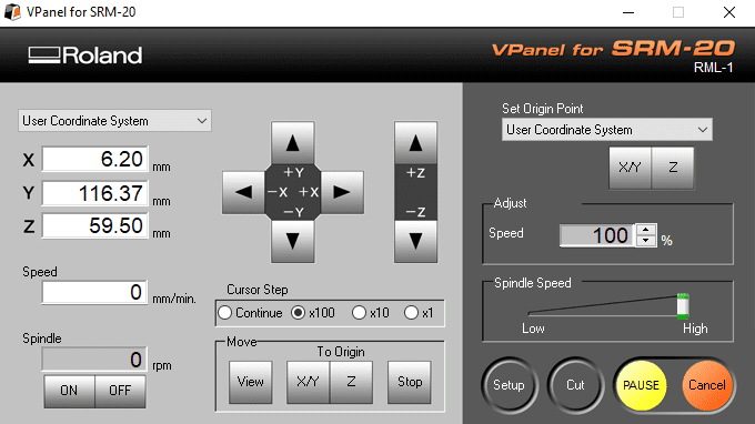
Next step: After saving the file, we click on the Cut option from the machine program to start the production process , After choose the file that you saved from FabModules in rml format.
%20(1).jpg)
%20(7).jpg)
%20(5).jpg)
%20(6).jpg)
%20(4).jpg)
%20(3).jpg)
%20(2).jpg)
Electronics Programing For programing the board using ArduinoIDE
After I prepared the board, I will prepare it:
Burning the Bootloader
After I finished designing and producing the board and installing the components, I will need to burn the bootloader onto it.
I can do this using an Arduino board as an in-system program (ISP).
To burn the bootloader, follow these steps:
Upload the ArduinoISP sketch onto your Arduino board. (You'll need to select the board and serial port from the Tools menu that correspond to your board).
Wire up the Arduino board and microcontroller (wires connected to pins 10 to RST, 11 to MOSI, 12 to MISO, 13 to SCK, GND, & VCC of the Arduino board to my microcontroller board).
Select "Arduino Duemilanove / ATmega328" from the Tools > Board menu.
Select "Arduino as ISP" from Tools > Programmer.
Run Tools > Burn Bootloader.
%20(8).jpg)
.PNG)
After preparing the board and it is ready for use, I will connect the servo motor and 2 LEDS and Button To the board, but this image is to illustrate how to connect the components
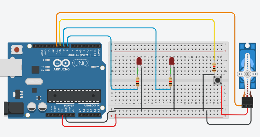
Servo motors have three wires: power, ground, and signal. The power wire is typically red, and should be connected to the 5V pin on the board. The ground wire is typically brown and should be connected to a ground pin on the board. The signal pin is typically orange and should be connected to a digital pin on the board.
I will connect components to the project board and this picture below shows that:
and program the board using the program using ArduinoIDE
A boolean holds one of two values, true or false. (Each boolean variable occupies one byte of memory.)
-Attach the Servo variable to a pin.
-pinMode(LED, OUTPUT);
-In the program, pin ---, which has LED connected to it, is set up as output in the setup function.
-In the main loop, the state of the buttonPin is saved in the variable ButtonState.
-If (previousButtonState! = ButtonState && buttonState == HIGH) {myservoEnabled =! myservoEnabled;}
If the previous button is equal to buttonState, which means buttonState is equal to HIGH (as if I pressed the button), and if the condition statement is met, reset the myservoEnabled to zero.
-if (myservoEnabled == 1) { digitalWrite (LED, HIGH); digitalWrite (LED1, LOW); myservo.write (0); delay (10000); myservo.write (180);delay (150)
If the servo motor works, turn on the led, turn off the led1, and move the servo motor from angle 180 after a period of time to angle 0 over a period of time.
-else {digitalWrite (LED, LOW);digitalWrite (LED1, HIGH);myservo.write (0); ;}
If the servo motor does not work, turn off the LED, turn on LED1, and move the servo motor to angle 0
-previousButtonState = buttonState;
Means the previous button is equal to the button state
.PNG)
Computer-controlled machining
I made a cat bowl after designing it on Fusion 360 and saved the file in stl format to cut it onto a Roland SRM-20.

First, I will cut a plank of 150 mm in width and 200 mm in length
.jpg)
Then I will make the height of the board that I have cut to 60mm using this machine
.jpg)
The length of the plank that I cut is ready. As for the width, I will reduce it with this machine to 150mm
.jpg)
After that I prepare the design file with SRP Player
I will set the origin of the side of the body so that the machine can grind it correctly. Second: I will choose the type of grinding and each type depends on the design details and also each type has a special brush.
And I chose - the fastest cutting time using the 1/8 SE 4FL bit BallNose.
.PNG)
.PNG)
Third: Choose the type of material which I will milling it, Fourth: The program will simulate the milling process and display the expected completion time.
.PNG)
.PNG)
After adjusting all the settings, I click on start cutting
.PNG)
After that, I prepare the wooden plank inside the machine and put it in place and prepare the machine and the brush that I will use, which is 1/8.
.jpg)
.jpg)
.jpg)
.jpg)
.jpg)
.jpg)
After completing the cutting, we use the tools that I mentioned in the pictures above, and with the help of the engineer Yazan in supervising the work, I will cut the excess pieces from the cat dish, so that the final shape will be as it is in the picture below.
.jpg)
The last stage of assembling the project
After applying the acrylic parts together and after preparing the electronic board and installing the project mechanism that you printed and programmed the board.
The final shape of the project was as it is in the picture:

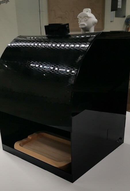
For the sake of testing I have written the code that the machine should place the food every five seconds.