Assignment
Week9: Input Devices
Assignment
- group assignment
- Probe an input device(s)'s analog and digital signals
- individual assignment
- Measure something: add a sensor to a microcontroller board that you have designed and read it.
My Work
Group Assignment
Compare the performance and development workflows for different microcontroller families(link )
Attiny3216 breakout board
For doing experiment in upcoming weeks, I made a breakout board with AVR 1 serires microcontroller that I want to use.
I selected Attiny3216 because it has 18 pins(out of 20 pins in total) can be used as IO pins.
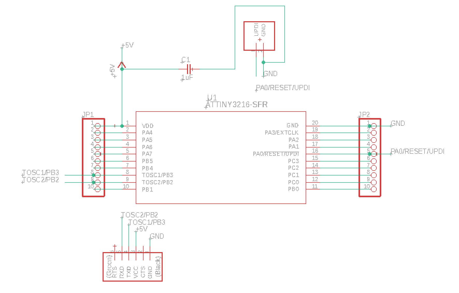
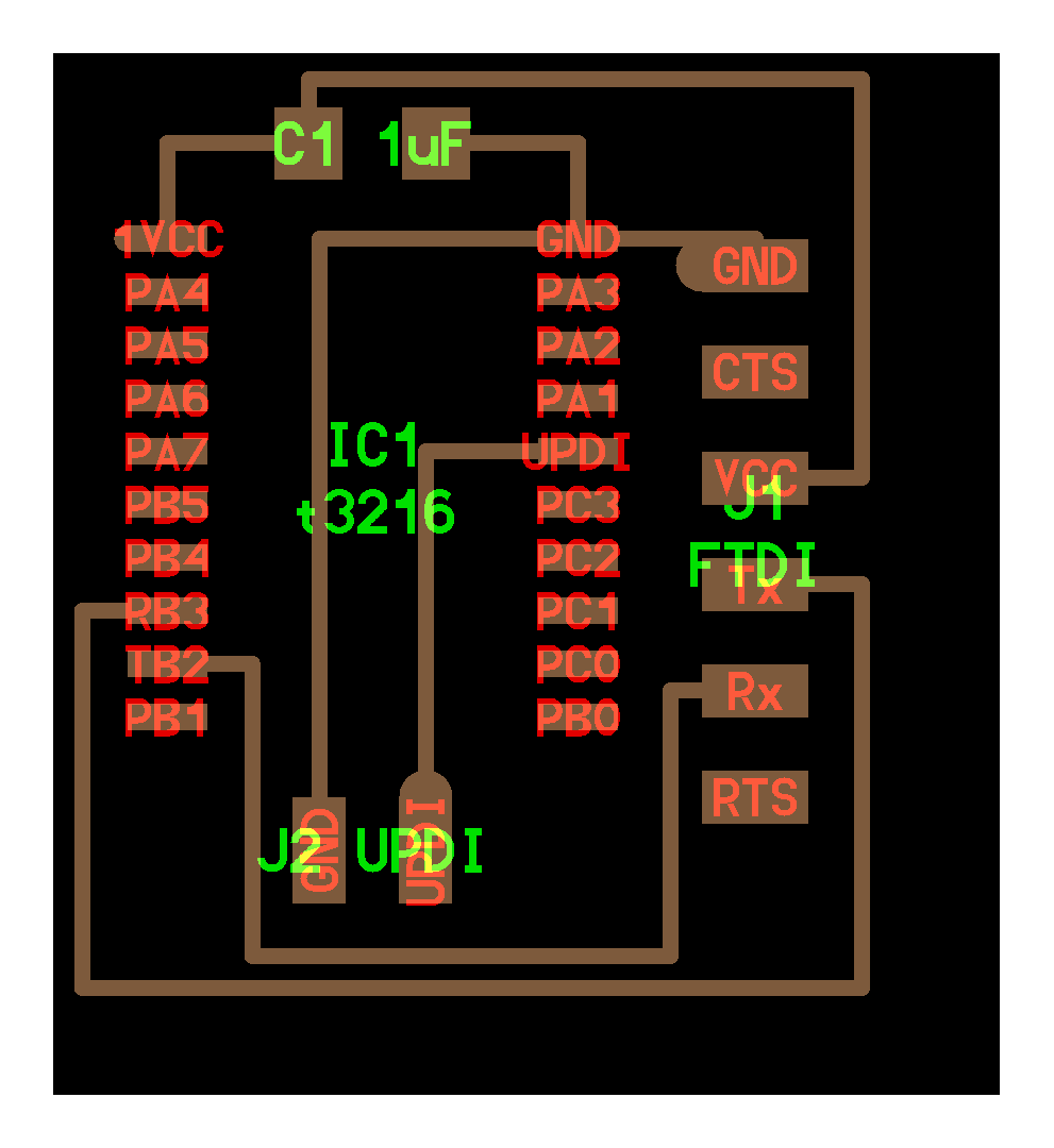
Design breakout board
I designed a breakout board schematic by EAGLE based on ATtiny 3216 datasheet.
Refs:
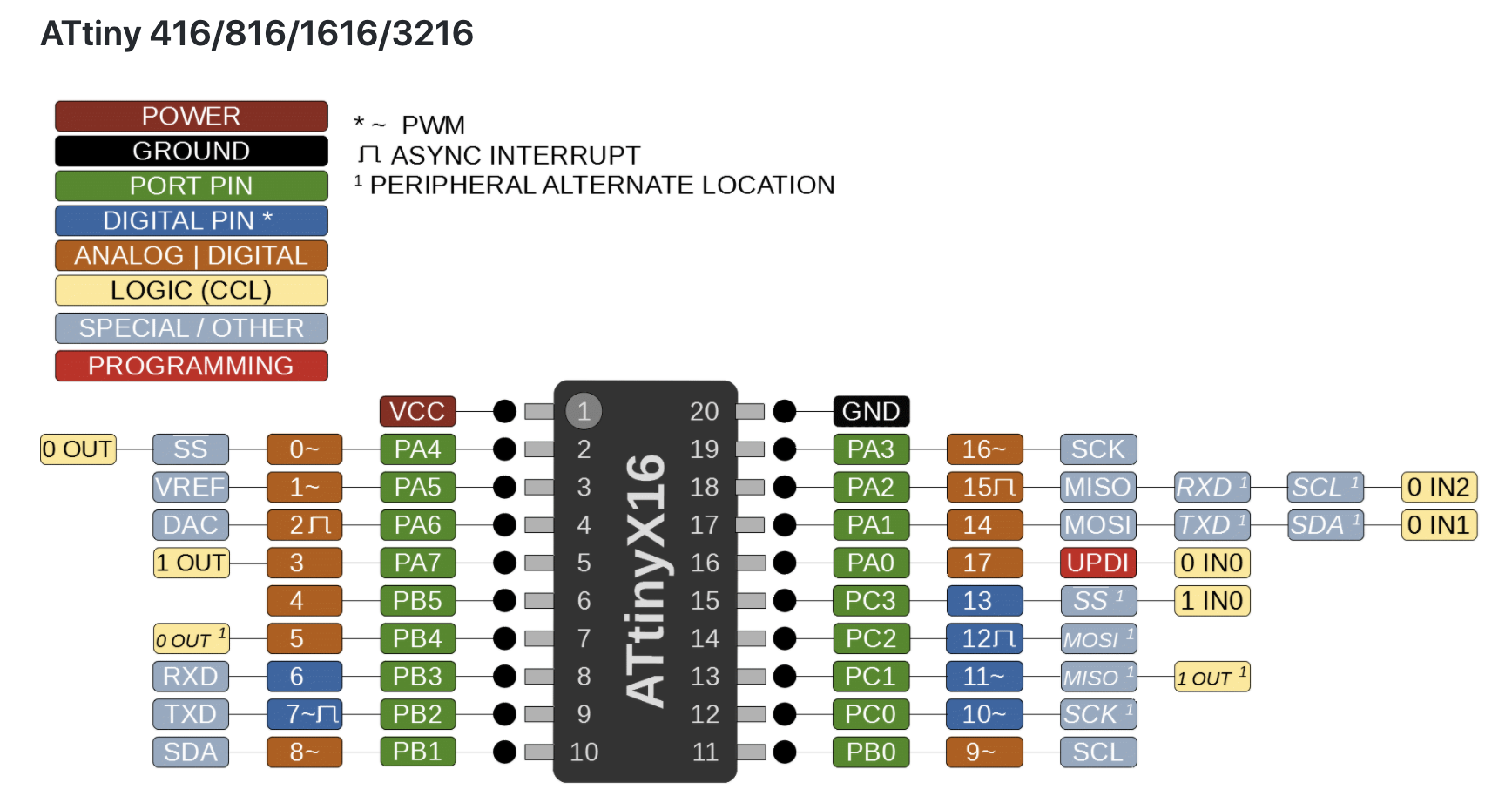
Main feature of ATtiny 3216 is as follows:
- GPIO Pins: 18 (17 usable)
- ADC Channel: 12 (11 usable)
- Clock Options: Internal 20/16/10/8/5/4/1 MHz
- Interface: UART, SPI, I2C
- Flash (program memory): 32768 bytes
- RAM: 2048 bytes
- EFPROM: 256 bytes
Files:
Refs:

Design breakout board - Tips & Errors!
Tips: 1) Search parts and add to EAGLE library
- If you cannot find a key (e.g. "Attiny3216")in Fab Inventory or cannot find parts by the key in DigiKey, check Ultra Librarian and download the parts.
- on EAGLE
- Control Panel > File > New > Libruary > Open untitled.lbr window
- on untitled.lbr window
- File > Execute Script > Browse and select: Library.scr > Open
- new library will be made Save > select folder and title as ATtiny3216
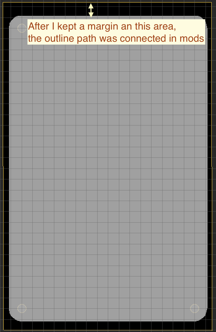
Tips 2) Save the margin of the schematics

Tips 3) How to design a drill hall fitting with breadboard
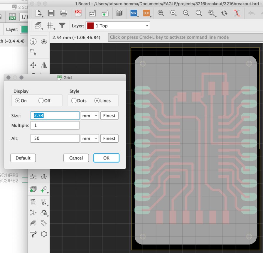
Set the Grid size as "2.54mm" that is the distance between halls of breadboard.
Usually, breadboard has width of only 6 holes + (2 holes margin) + 6 holes. It's important to make the breakout board "narrow" as long as you can for saving the space to connect jumper cables.
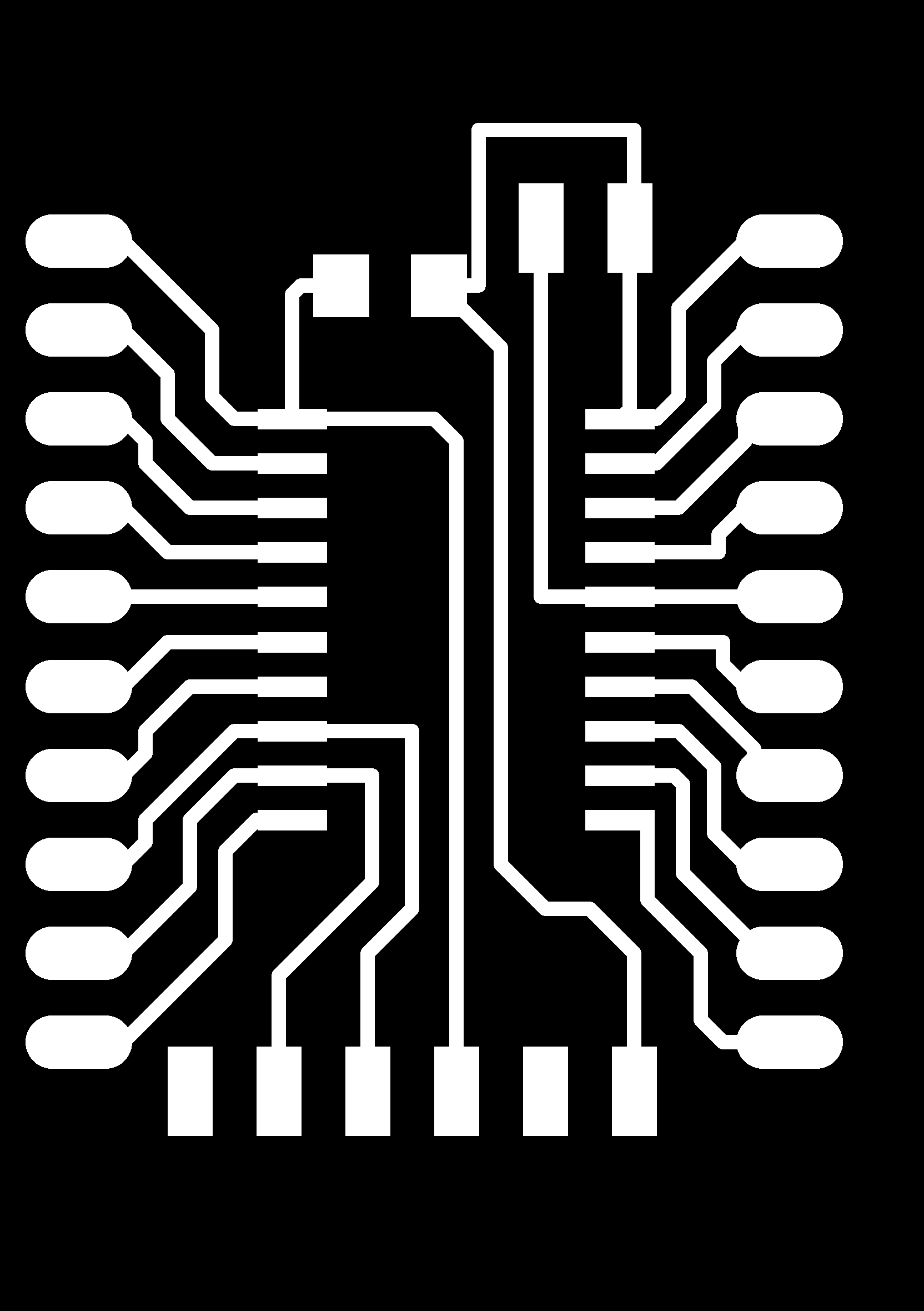
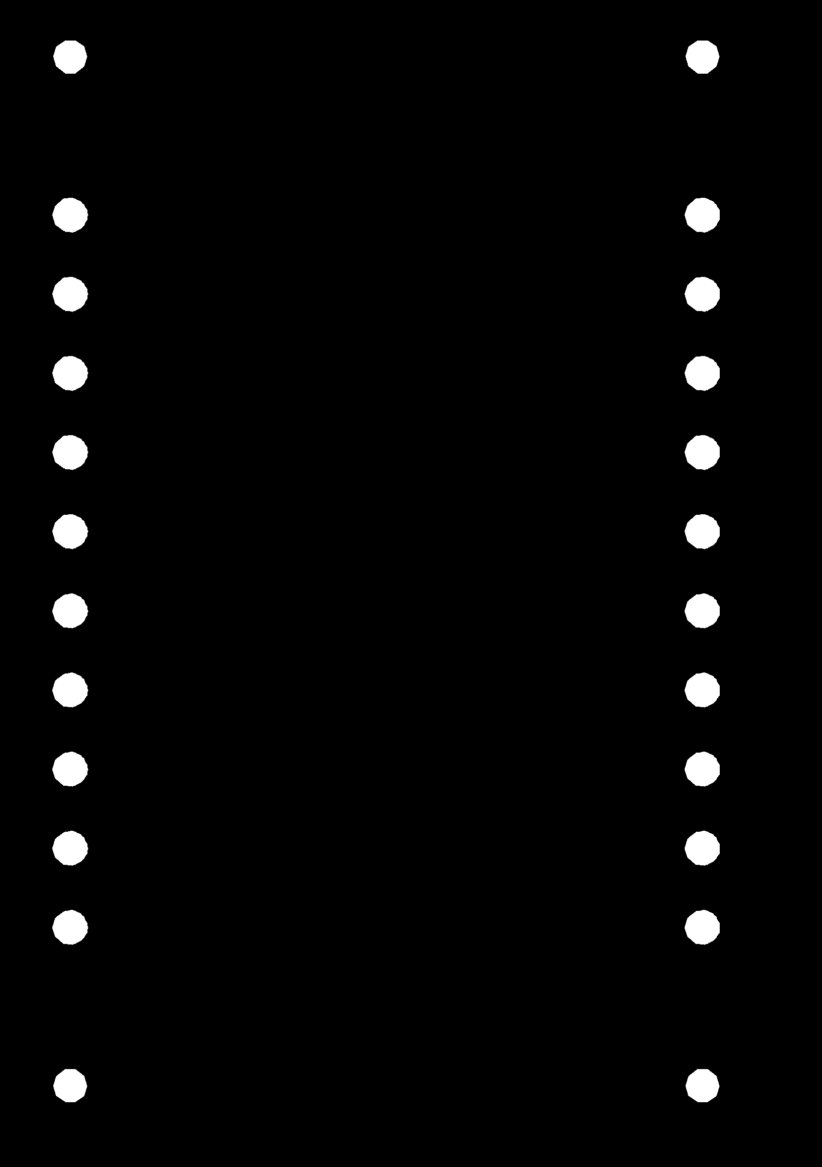
Tips 4) How to make a drill hall in board image on EAGLE
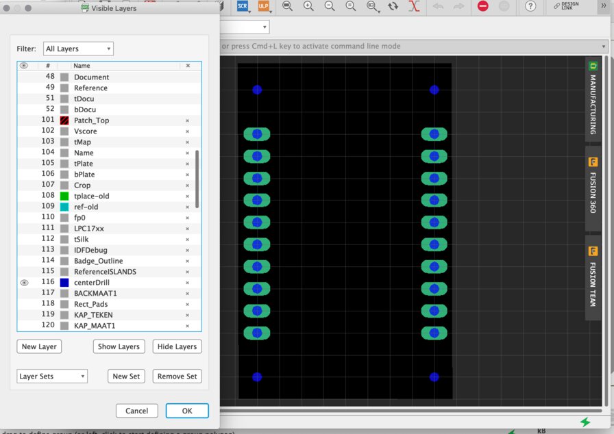
Use "drill-aid.ulp" at command box on EAGLE
SET FILL_LAYER 116 1;run drill-aid 0
Mill and assemble breakout board
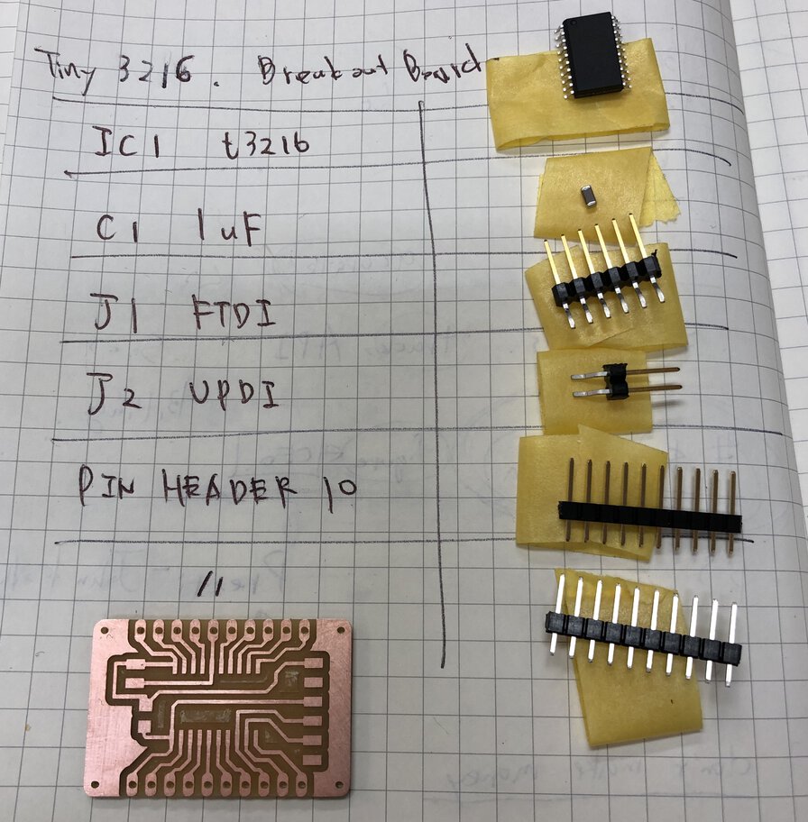
Assembled the board by soldering.
When putting through the male header pins solder through the board, it's good to put the pin into breadboard to fix the position and angle of the pins.
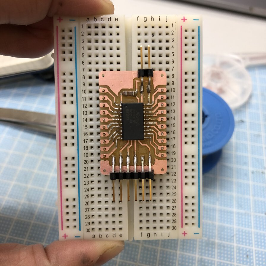
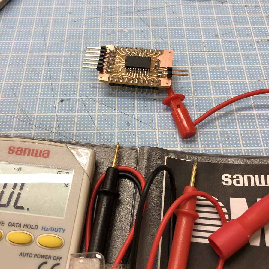
Assemble completed and test the clearance and continuity
Write program to Attiny3216 breakout board
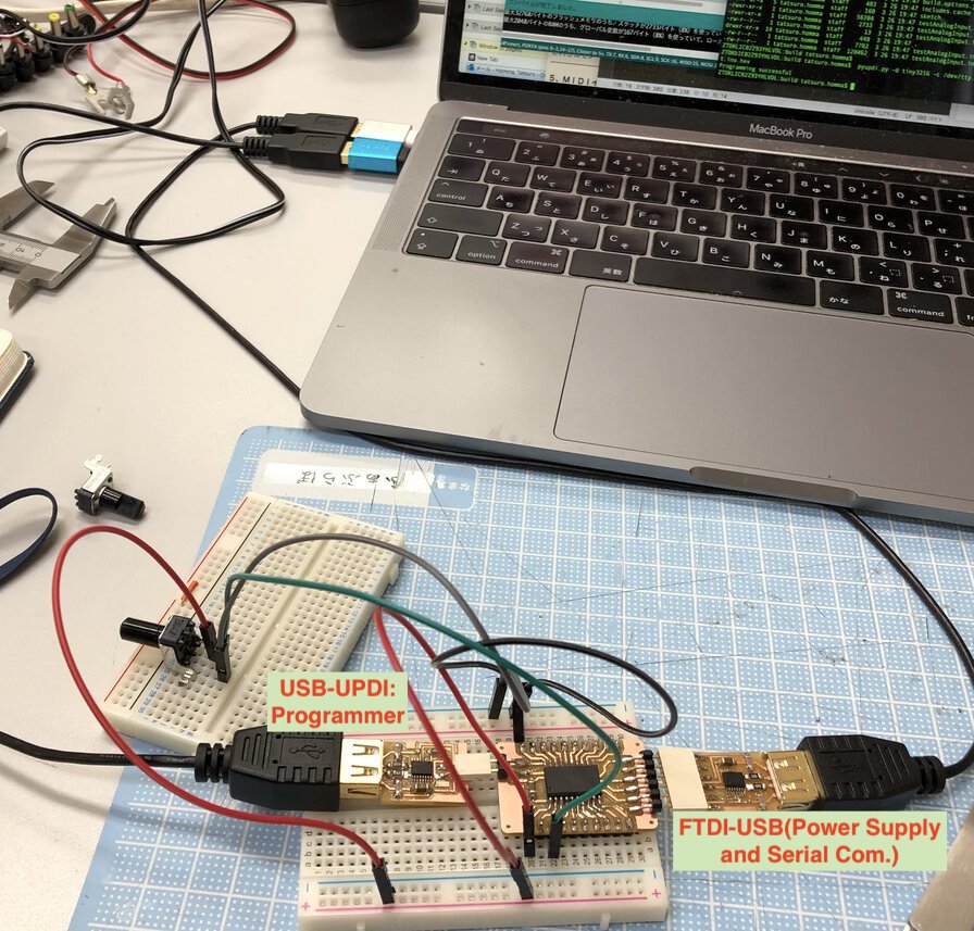
For writing probram, I wrote procedures in the past assignment pages:
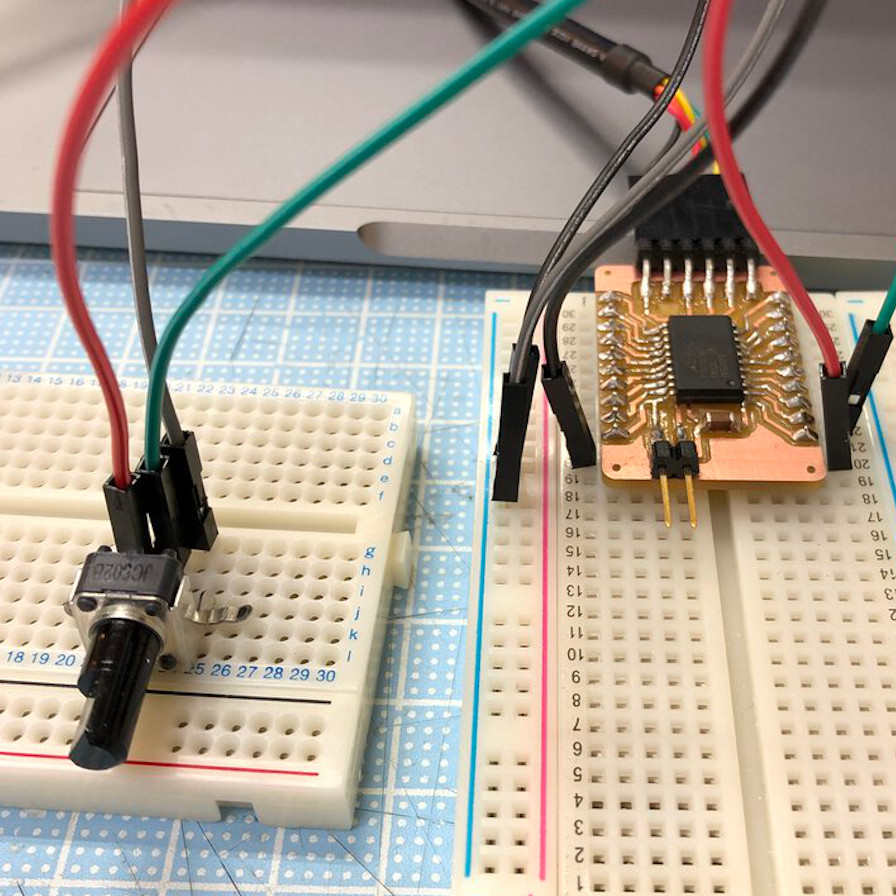
Potentiometer connected to Attiny3216 breakout board
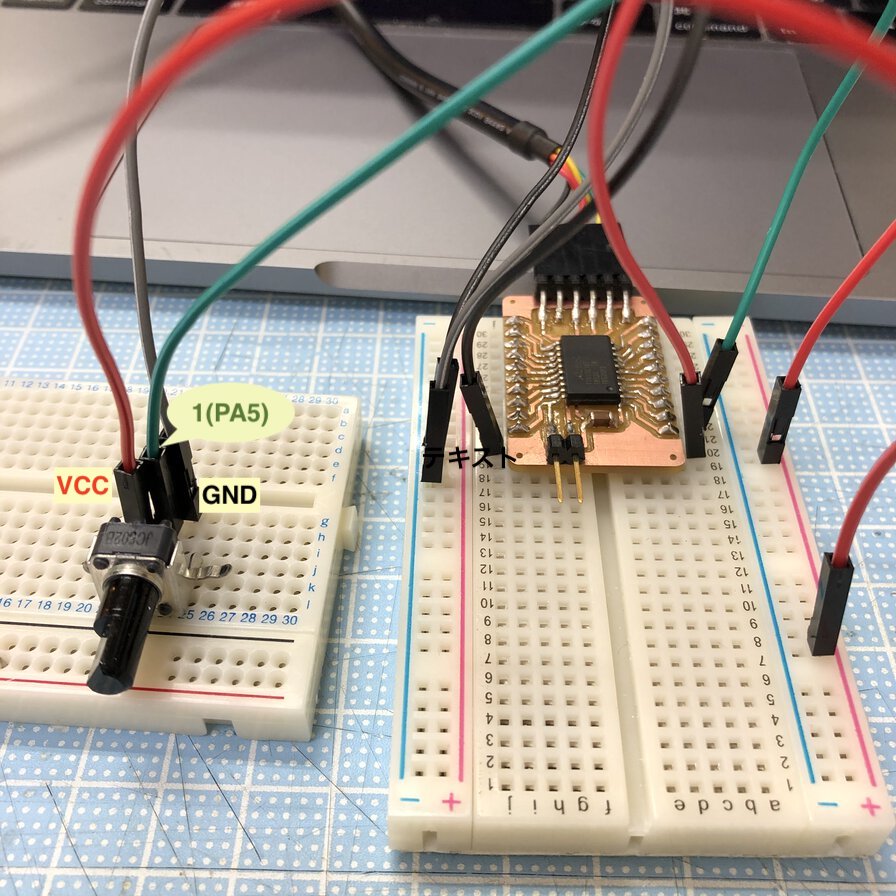
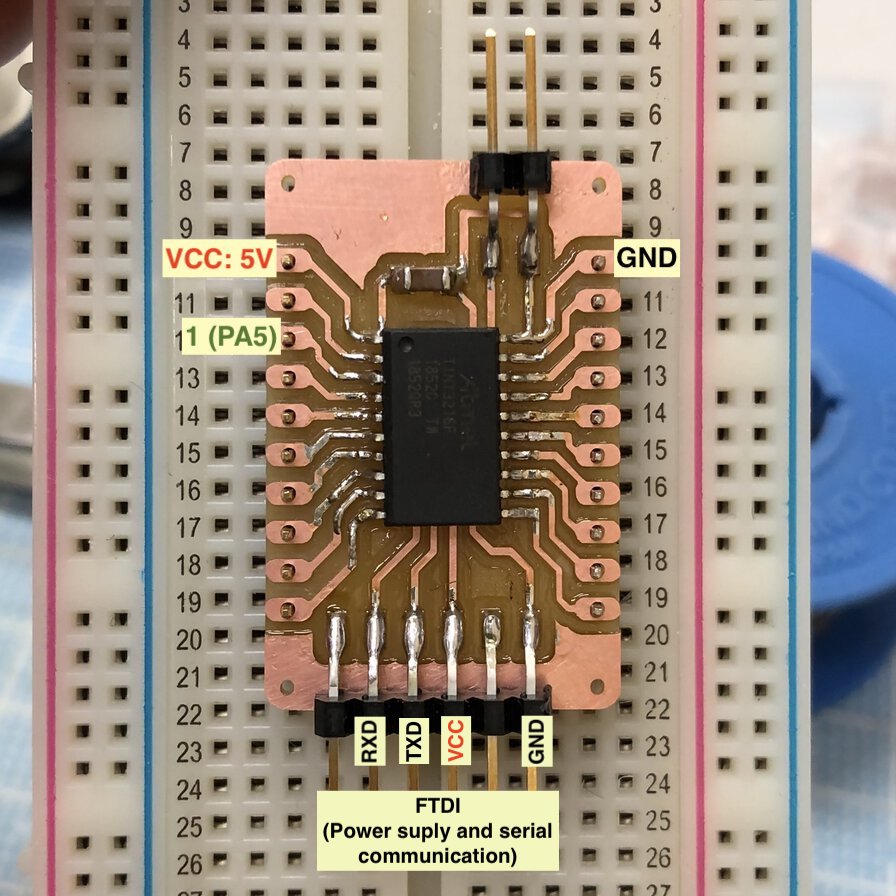
Connection (ATtiny3216 - potentiometer)
- VCC - VCC
- 1(PA5) - control pin
- GNC - GND
Source code - testAnalogInput.ino
Experiment
Here is my "hero video" of this week.Outcome
Sensor value from 1 potentiometer via analogRead() is from 1023(low) to 0-7(high).
Though potentiometer value is effective to check slight change in the volume of resister, the max(high) value is not necessarily achieve to zero. It seems to be effected by stability of voltage, wire connection or charactor of the resister device. If we want to get a zero value from "max" dialed potentiometer, it's good to calculate the analogRead() value by a certain grades, like gain = analogRead(1)/60;
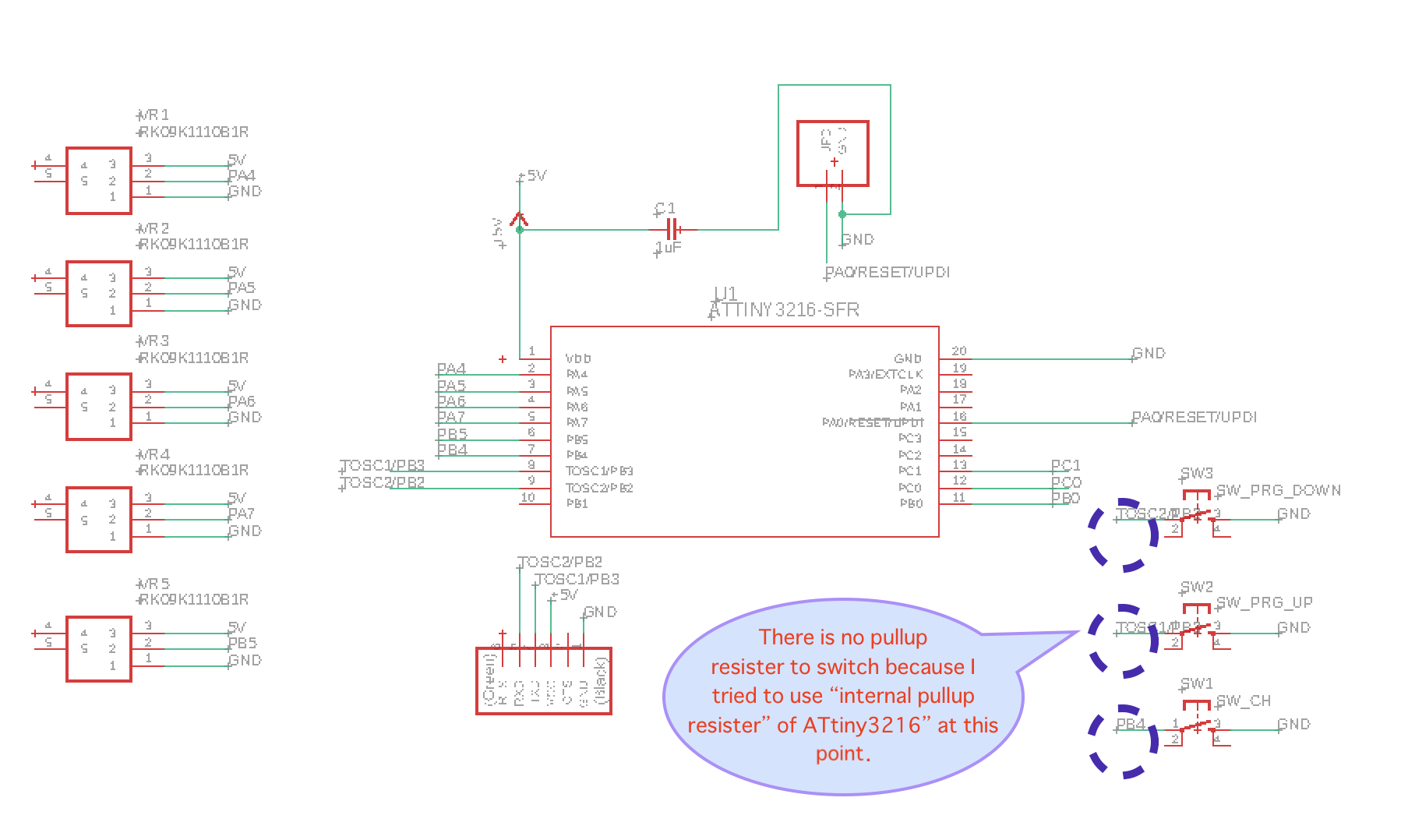
Design Original Input Board
Though I did not have access to lab because of preventive measures of COVID-19, I tried to make my input board design of final project. As I want to use multiple potentiometers and switches to control MIDI library, I used ATtiny3216 and connected the input devices to GPIO pins.
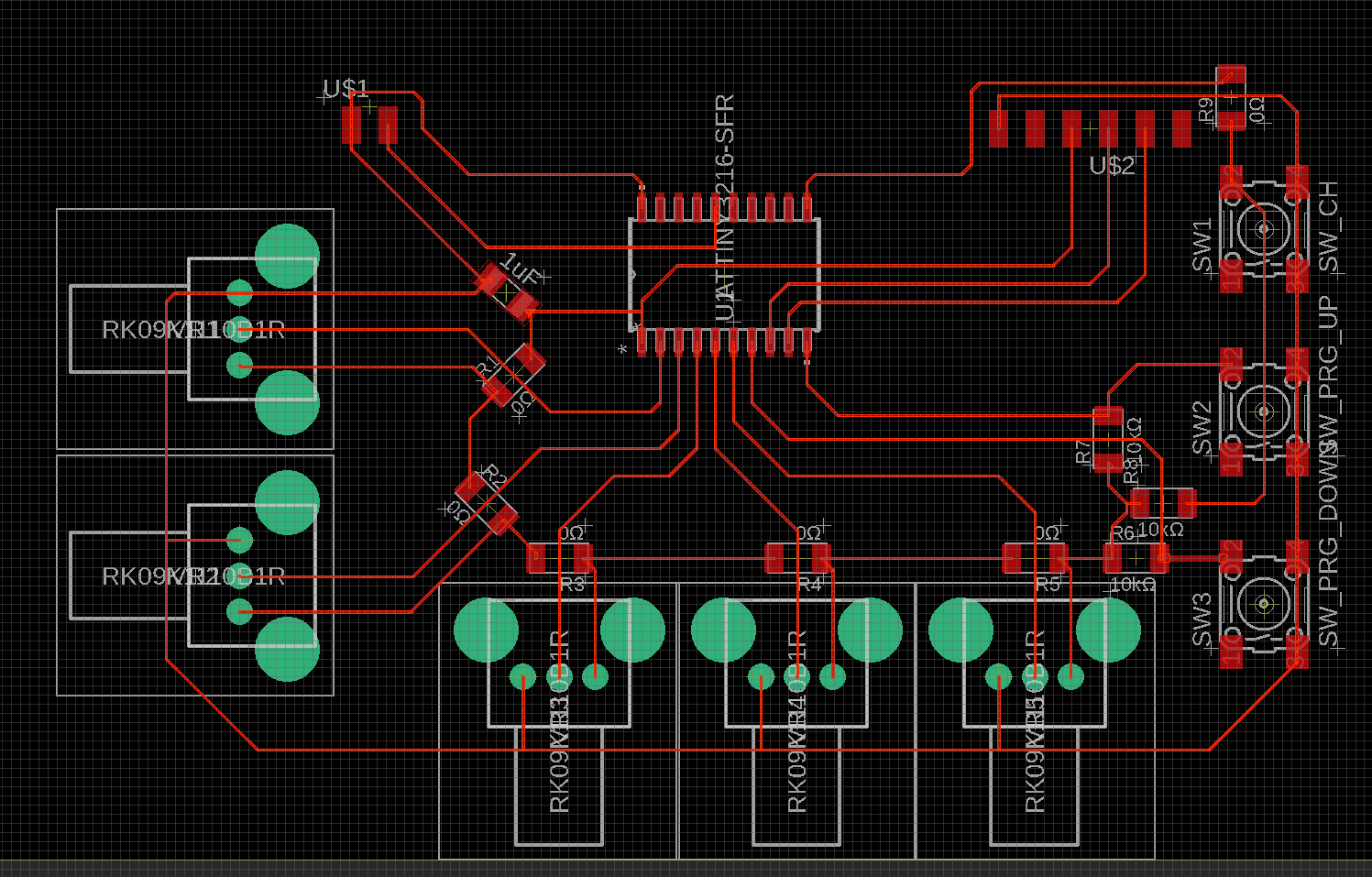
This is my first design of input board.
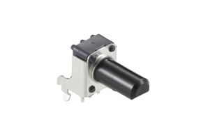
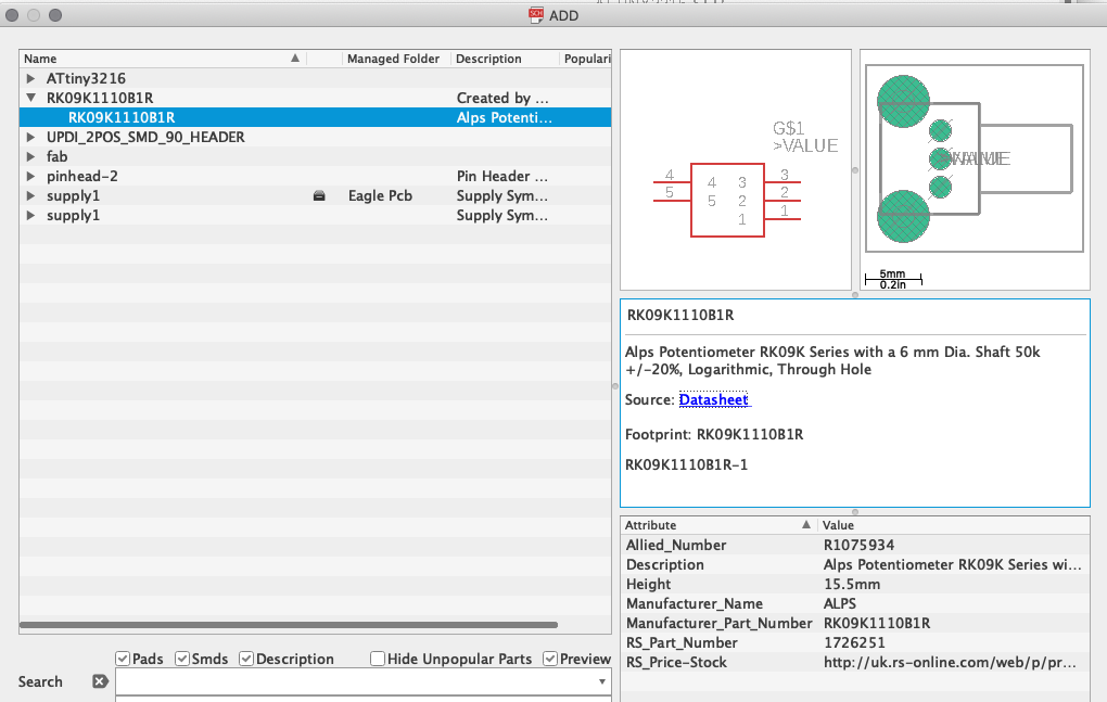
I added the EAGLE library of my potentiometer, "RK09K1110B1V" by ALPS, from "PCB Part Library" web site.
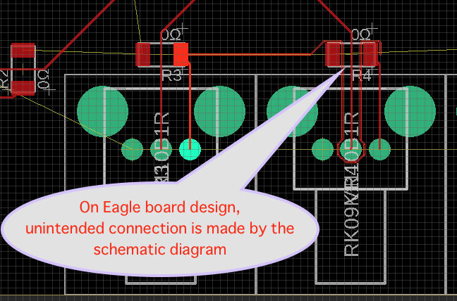
I had 2 errors on this schematic image.
1st Error - cross section and unintended path at board pattern
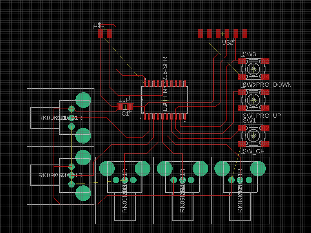
2nd Error - unexpected behavior of the analog / degital read without pullup resister.
Reading datasheet of ATtiny3216, I found that the description - "16.3.2.3 Pin Configuration The Pin n Configuration register (PORT.PINnCTRL) is used to configure inverted I/O, pullup, and input sensing of a pin. ~ Pullup of pin n is enabled by writing a ‘1’ to the Pullup Enable bit (PULLUPEN) in PORT.PINnCTRL".
Also, I checked Digital pins of Arduino foundation tutorial that's saying about pinMode(pin, INPUT_PULLUP);. For avoiding complexity in assembling board, I tried to use internal pullup by .ino code (For final project, I want to use arduino code (not C language code) for my input/output board for using Adafruit NeoPixel library that supports .ino code. )
Then I made an experiment testing electronics using ATtiny3216 breakout board and bread board with these senseors.
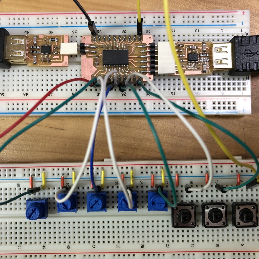
Source code - testAnalogInputPullup.ino
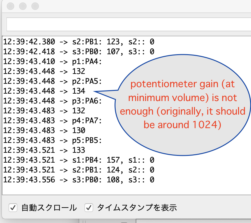
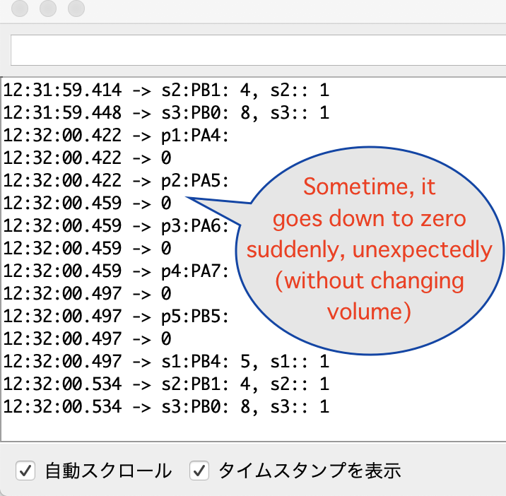
At first, it looks the outcome of sensor values (especially the values of analogRead() from potentiometers) are not stable.
I did some trial amendment that changes line, check resister value of sensors by multimeter etc. I could not elaborate the situation actually.
Then I added 10kΩ pullup resisters to switches.
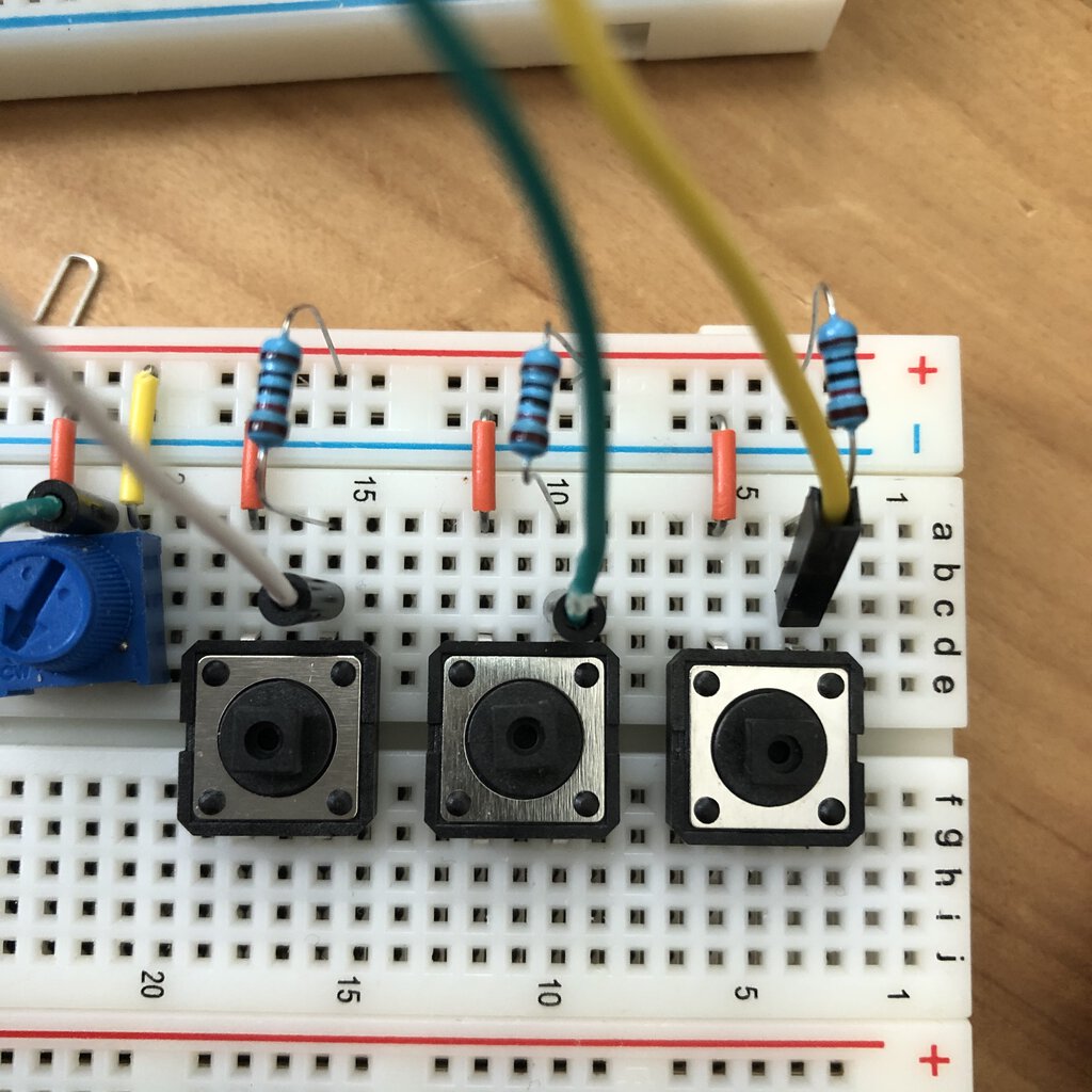

After added 0kΩ pullup resisters to switches, the values look to be stable.
Source code - testAnalogInput_noInternalPullup.ino
testAnalogInput_noInternalPullup.ino
Then I refined the schematic diagram in terms of
- 1) Workaround routing against 0kΩ resister
- 2) Added 10kΩ pullup resister to switch
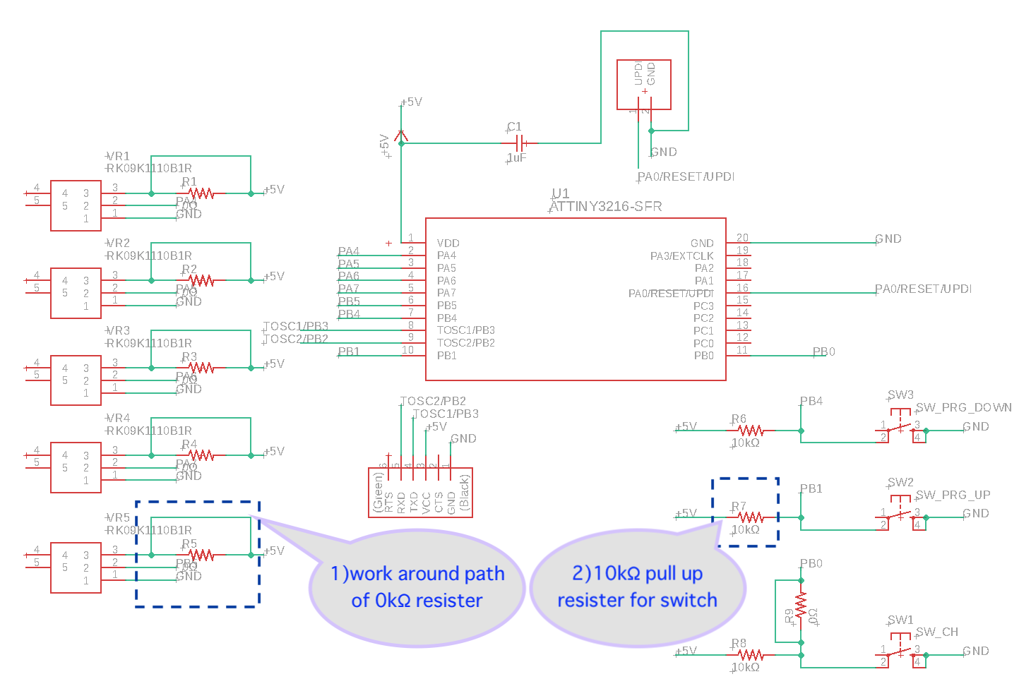
Actually, it's not completed as of 21 APril - I need to setup the minimum path size for 16 mil in DRC rule. I will update this altogether when I will add the output of NeoPixel to the same board (as input-output board of my final project) .
Link to final project input board
After experiment in output device week, I decided to separate the input board and output board in different boards for modularity of system and performance (Multiple LEDs attached in NeoPixel takes time and microcontroller waits for finishing sequential blinking. It would be better for controller at output board to concentrate on output process without preventint input process. )
Including those ideas above, I designed, milled, assembled and embedded my original input board after I came back to lab from staying at home in COVID-19 situation. That work is written in a input deviices pages of my final project.
Potentiometer with Mozzi library (connected to Arudino UNO)
As my final project is for music instrument device, I want to make sounds connecting potentiometer using Mozzi library.
Source code - Scale.ino
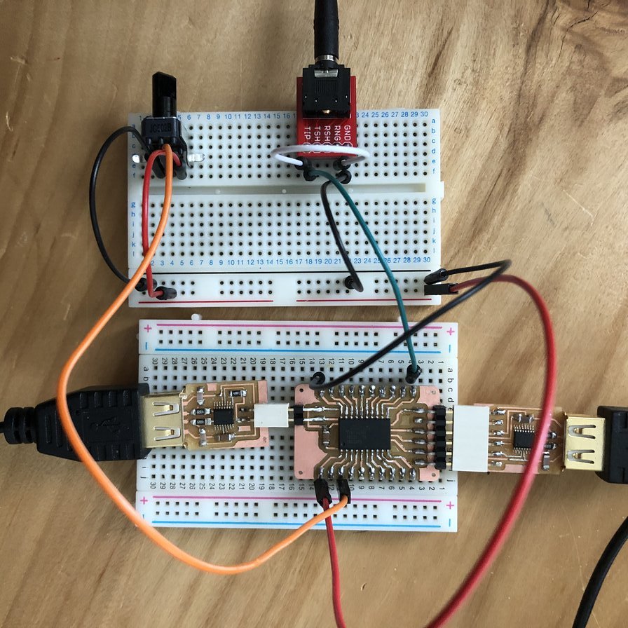
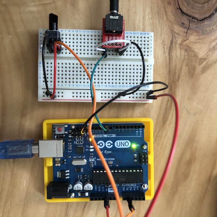
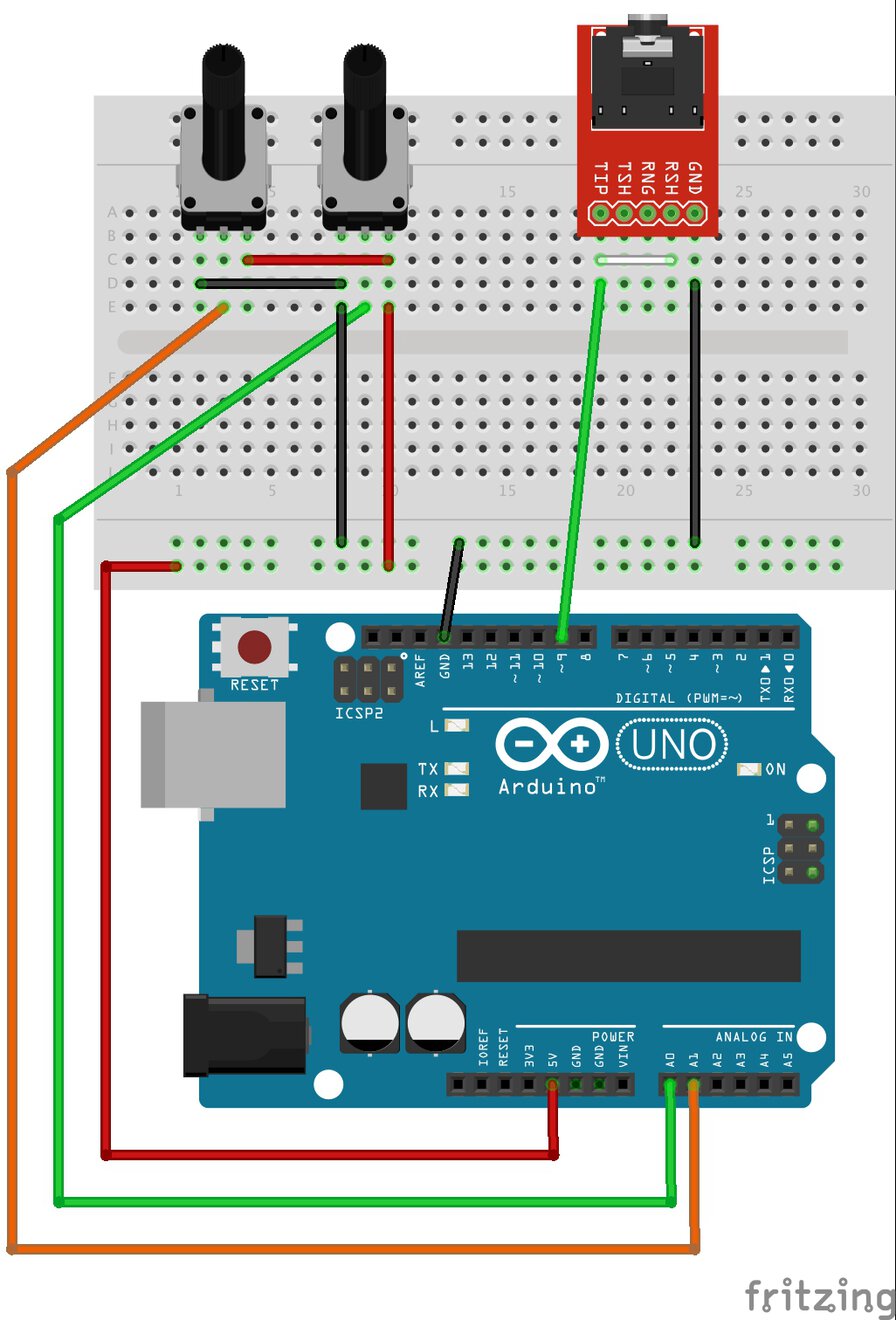
My first idea is writing .ino code to ATtiny3216 board and connecting breakout board pins to potentiometer and audio output jack.
However, it's difficult to write ".ino" code including Mozzi library to ATtiny3216. It seems because there is no compatibility in Mozzi library in Attiny 3216 at least default configuration. So I moved to 2nd idea - embedding the program (with Mozzi) to Arduino Uno.
Connection (Arduino UNO - breadboard
- VCC - VCC for potentiometer x 2
- GNC - GND for potentiometer x 2 and Audiojack
- Analog 0 pin - Potentiometer 1(stepGain)
- Analog 1 pin - Potentiometer 2(interval)
- Digital 9 pin(*) - TIP of Audio Jack
(*)Arduino Digital 9 pin is reserved for audio output by Mozzi library.
Connection to audio system
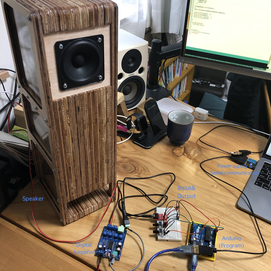
Experiment
Outcome
16:02:34.780 -> stepGain: 17, interval: 0
16:02:34.780 -> stepGain: 17, interval: 0
16:02:34.817 -> stepGain: 17, interval: 3
16:02:34.817 -> stepGain: 17, interval: 19
16:02:34.855 -> stepGain: 17, interval: 52
16:02:34.855 -> stepGain: 17, interval: 93
16:02:34.855 -> stepGain: 17, interval: 137
16:02:34.893 -> stepGain: 17, interval: 173
16:02:34.893 -> stepGain: 17, interval: 212
16:02:34.930 -> stepGain: 17, interval: 251
16:02:34.930 -> stepGain: 17, interval: 305
16:02:34.964 -> stepGain: 17, interval: 393
16:02:34.964 -> stepGain: 17, interval: 508
(omitted)
16:02:35.911 -> stepGain: 17, interval: 752
16:02:35.948 -> stepGain: 17, interval: 760
16:02:35.948 -> stepGain: 17, interval: 1023
16:02:35.948 -> stepGain: 17, interval: 1023
16:02:35.981 -> stepGain: 17, interval: 1023
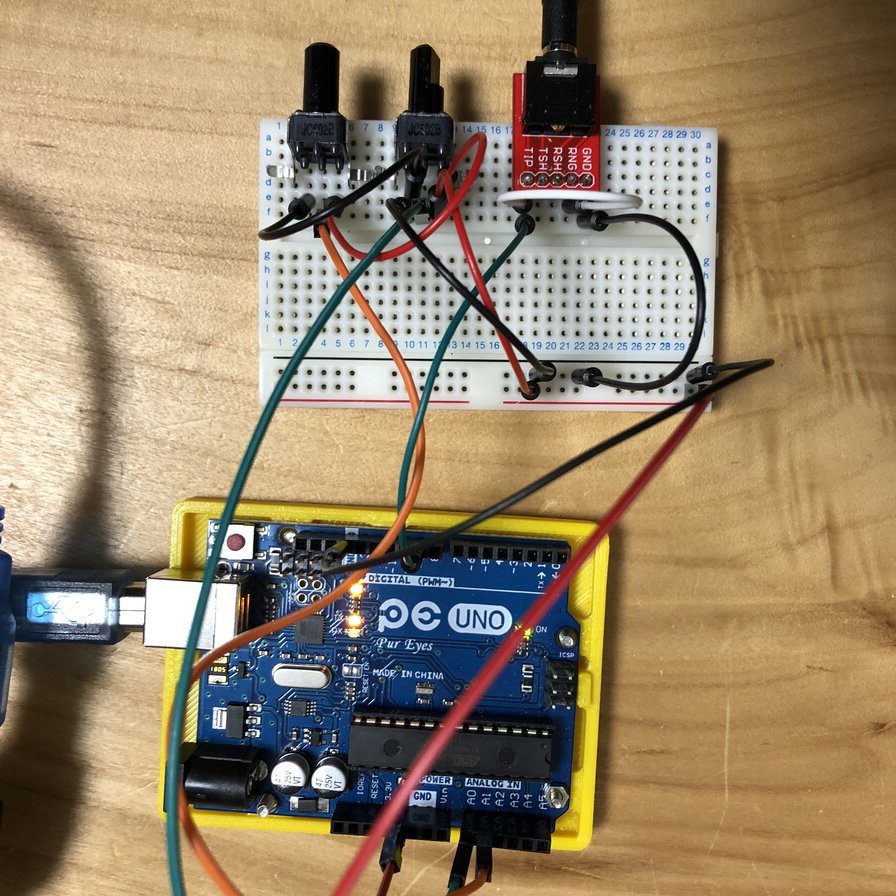
Serial monitor example when I counter-clockwise rotated potentiometer 2(interval) - parallel circuit of resister
When I connect the two potentiometer in parallel circuit, the value that I can read from analogRead() goes to 1023.
Parallel circuit of 2 potentiometers.
16:28:55.636 -> stepGain: 17, interval: 0
16:28:55.672 -> stepGain: 17, interval: 0
16:28:55.672 -> stepGain: 17, interval: 1
16:28:55.710 -> stepGain: 17, interval: 5
16:28:55.710 -> stepGain: 17, interval: 8
16:28:55.710 -> stepGain: 17, interval: 18
16:28:55.747 -> stepGain: 17, interval: 41
16:28:55.747 -> stepGain: 17, interval: 113
16:28:55.784 -> stepGain: 17, interval: 251
(omitted)
16:28:55.784 -> stepGain: 17, interval: 332
16:28:55.784 -> stepGain: 17, interval: 352
16:28:55.820 -> stepGain: 17, interval: 362
16:28:55.926 -> stepGain: 17, interval: 432
16:28:55.964 -> stepGain: 17, interval: 454
16:28:55.964 -> stepGain: 17, interval: 481
16:28:55.964 -> stepGain: 17, interval: 509
16:28:56.001 -> stepGain: 17, interval: 521
16:28:56.001 -> stepGain: 17, interval: 519
16:28:56.036 -> stepGain: 17, interval: 521
16:28:56.036 -> stepGain: 17, interval: 519
16:28:56.070 -> stepGain: 17, interval: 521
16:28:56.070 -> stepGain: 17, interval: 521
16:28:56.070 -> stepGain: 17, interval: 523
16:28:56.106 -> stepGain: 17, interval: 520
16:28:56.106 -> stepGain: 17, interval: 520
Serial monitor example when I counter-clockwise rotated potentiometer 2(interval) - serial circuit of resister
When I connect the two potentiometer in parallel circuit, the value that I can read are:
- 1st resister from analogRead(0)(stepGain ...above value of 17 is calculated in analogRead(0)/60): around 1024
- 2nd resister from analogRead(1)(interval) : around 512. 2nd resiter's value is affected by 1st resister's value.
In case of serial circuit, If you want to control multiple devices separately based on values for each resister, of course, you need to connect them by parrrel circuit.
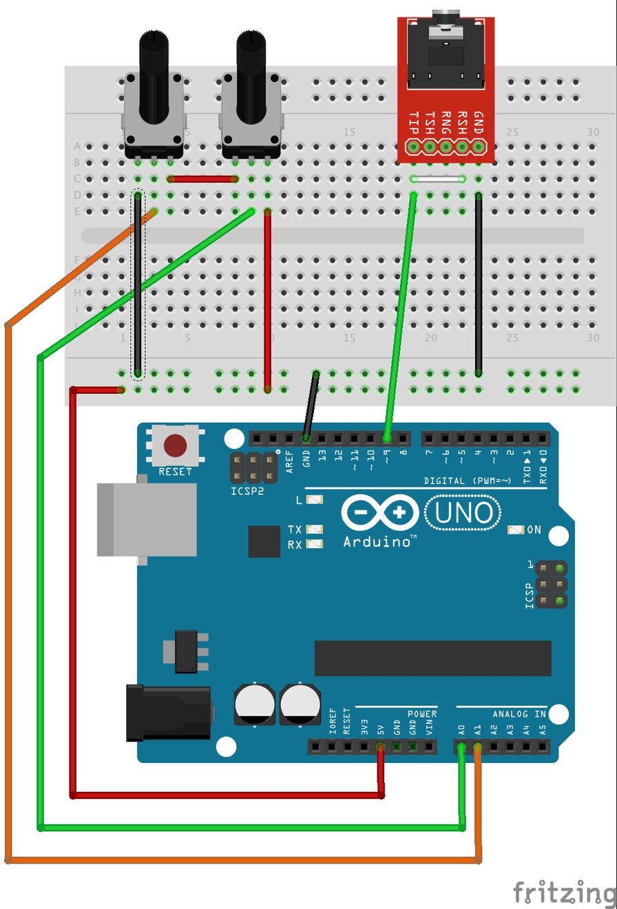
Serial circuit of 2 potentiometers.
ESP32Cam
I got a third-party ESP32-cam module and tried to test WiFi camera sample.
I followed an instruction in a blog (in Japanese). What I did is:
- Checked the cable spec
- Connect the cable and ESP32-CAM
- Setup the board
- Write the program
- Start ESP32-Cam
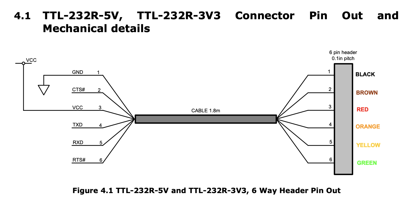
1. Checked the cable spec
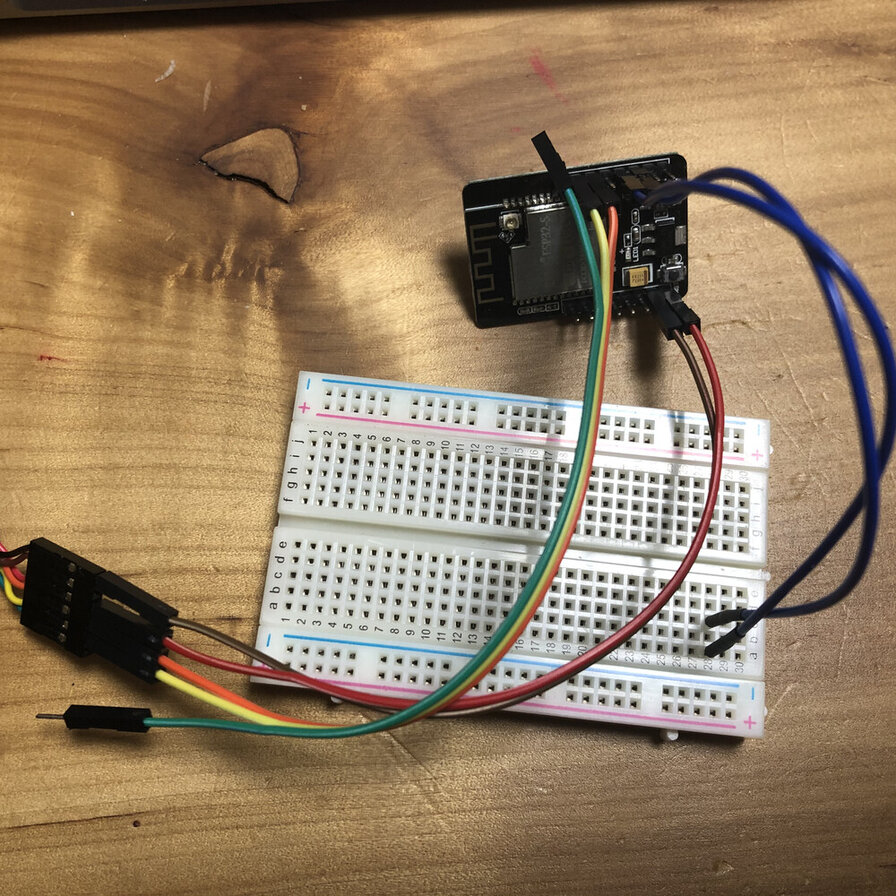
2. Connect the cable and ESP32-CAM
    USB-TTL           ESP32-CAM
    TXD ( Orange )    UOR
    RXD ( Yellow )    UOT
                    ( IO0 - GND )
    5V (Red)          5V
    GND (Black)       GND
When writing a program to ESP-32, short the IO0 pin and GND pin. (As I did not have female-female cable or pin, I used two male-female jumper cables and breadboard).
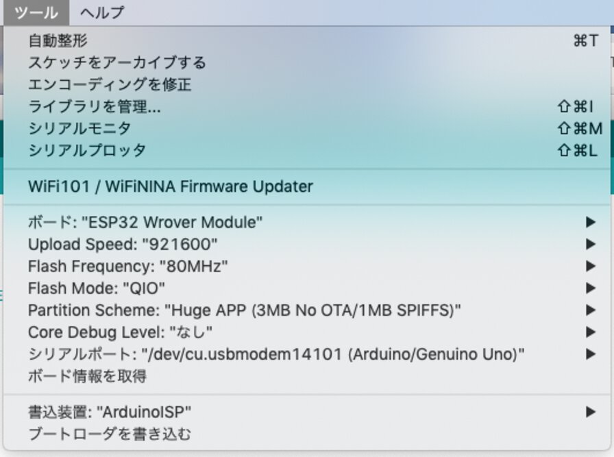
3. Setup the board on Arduino IDE
- Board: ESP32 Wrover Module
- Partition Scheme: Huge App(3MB No OTA)
- Flash Mode: QIO
- Flash Frequecy: 80MHz
- Upload Speed: 921600
4. Write the program
On Arduinoi IDE,
File > Sketch Examples > ESP32 > Camera Web Server
- Change the SSID and WiFi passowrd on that.
- Change the comment out definition of camera model and activate
#define CAMERA_MODEL_AI_THINKER - Write a program from Arduino IDE.
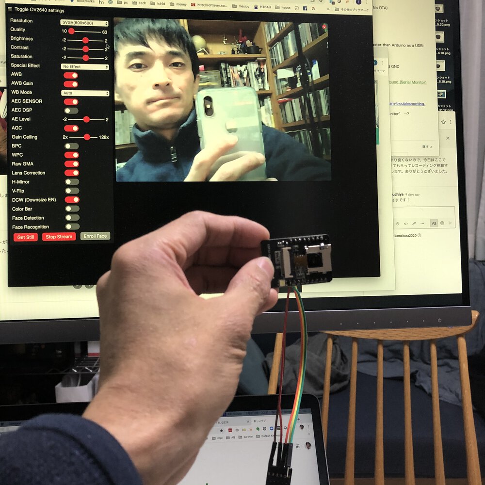
5. Start ESP32-Cam
1) Plug-off the short jumper between IO0 and GND
2) Push “RESET” button on ESP32-Cam
I had errors on WiFi connection in my home Wifi router. It might be caused by specification in WiFi or that security spec.
At a datasheet of ESP32-cam by AI Thinker, Wifi Specification is 802.11 b/g/n. My home wifi router might automatically connect to higher specification than that. After I changed the Wifi SSID and password to the one of tethering network provided by my smartphone, that worked.
Outcomes
I roughly checked the size of image and focus distance that can capture full area of the image
The camera setting is CIR(400x296)
| Size of image | Focus distance |
|---|---|
| 11cmx15.8cm small size of Japanese book(文庫本) | 16cm |
| 13cmx21cm (A5:Moleskine notebook) | 21cm |
| 21cmx30cm (A4:paper) | 33cm |
A datasheet of OV2640 (a camera embedded in ESP32-Cam) does not tell about fov(field of view, the angle for capturing image). As long as experiment it by CIR(400x296) setting, angle seems like around 72 degree.
My design of device in final project is shaped like a pot. This means the project needs a camera module over 90 degree of fov. I need to check if I can set it by ESP32-Cam (OV2640) or acquire the other camera module.
Files
Lessons Learned
- I learned from interfacing input devices of potentiometers with serial/parallel circuits and checked resister value basic electronics principles
- I checked the ESP32-Cam and web server sample. It's quite strong to provide real time camera server via Wifi. I need to check how I can procsss images from that camera
- Making ATtiny3216 breakout board, I will be able to experiment further application composition in upcoming weeks without accerssing to lab in COVID-19.
- For utilizing library (like Mozzi), I need to know about the requirement of micro controller specification.
References
- SpanceKonde/megaTinyCore
- a data sheet of Attiny 3216
- ATtiny3216 echo board sample in Fab Academy page of embedded programming.
- Program AVR 1 Series from UPDI(2020 Instractor Yuichi Tamiya
- Refs: EAGLE holes making(2020 Instructor, Yuichi Tamiya)
- Mozzi library.
- Start web camera server by ESP32-cam driven by battery - a blog (in Japanese)
- a datasheet of TTL-232R Cable (TTL-232R-5V)
- a datasheet of ESP32-cam by AI Thinker