
TASK TO DESIGN THE PCB
- Redraw the echo hello-world board and:
- Add (at least) a button and LED (with current-limiting resistor)
- Check the design rules, and make it
Redraw the echo hellow-world board
So lets Start ,this week we have to design PCB Borad that Based On Micro Controller, So for the Design we are fimilare with EAGLE (Easily Applicable Graphical Layout Editor). Becasue we can easily redraw the required cirucit in this software as well as pcb board can be easy generated in it.
EAGLE can be downloaded from HERE
After the installation of the EAGLE the next target is to get fimilare with. Here is the very easy and usefull tutorial from which we can learn how to draw the circuit diagram in this software. So i used to design the with the helf of the This Tutoural HERE
The Next very important thing is to include fab library to the eagle. It is really important because the component that we use to draw any circuit must be avalible in our fablab. In this regard fab library help us to give easy path to include component with proper pcb layout.
Here is the eagle library to download
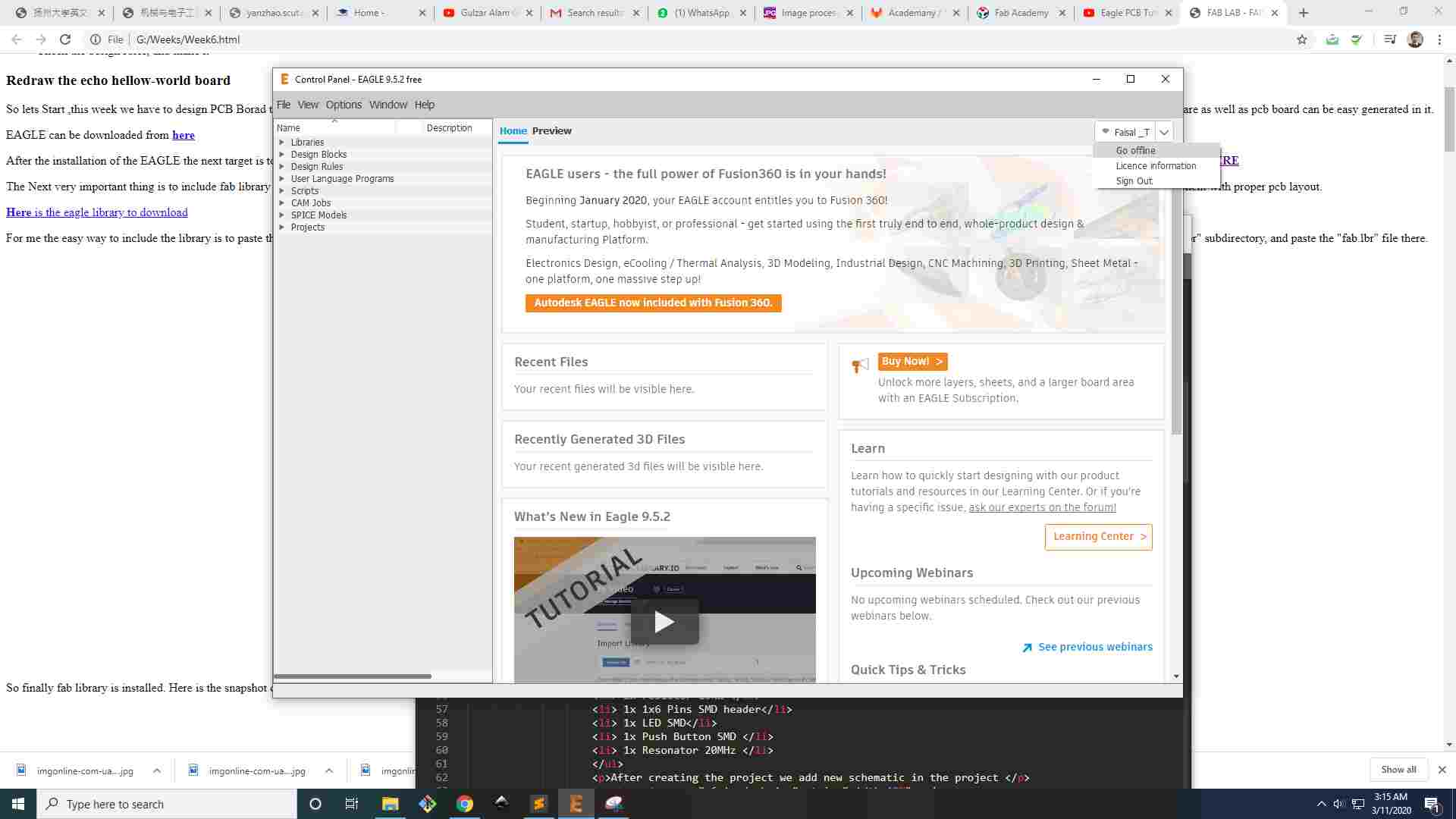
first of all Install the latest Eagle Software(9.5.2 version) and Sign Up at the Autodesk page and change the Seeting for off line
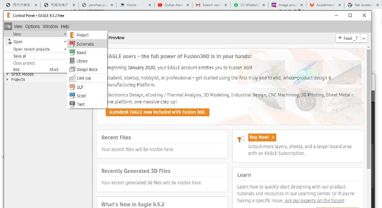
Now Open the file and go to the new and for Schematic for the new file:
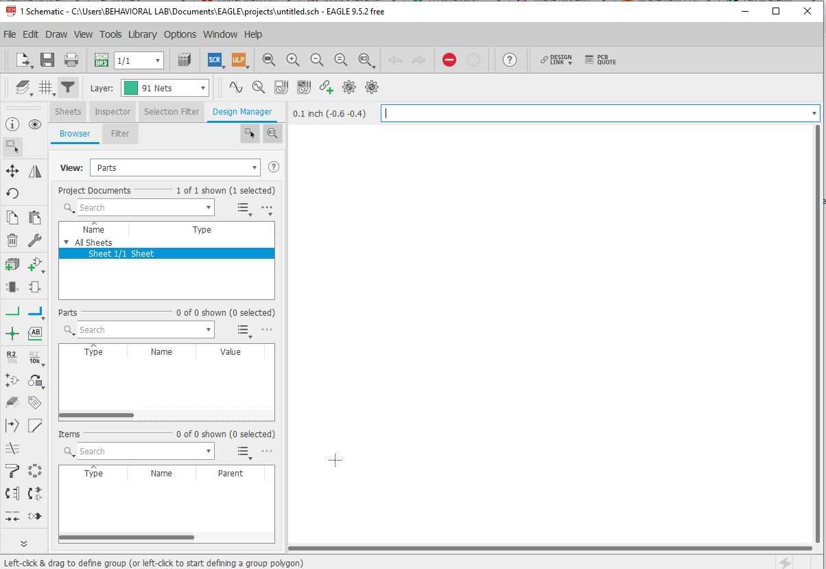
Now find this kind of Window:
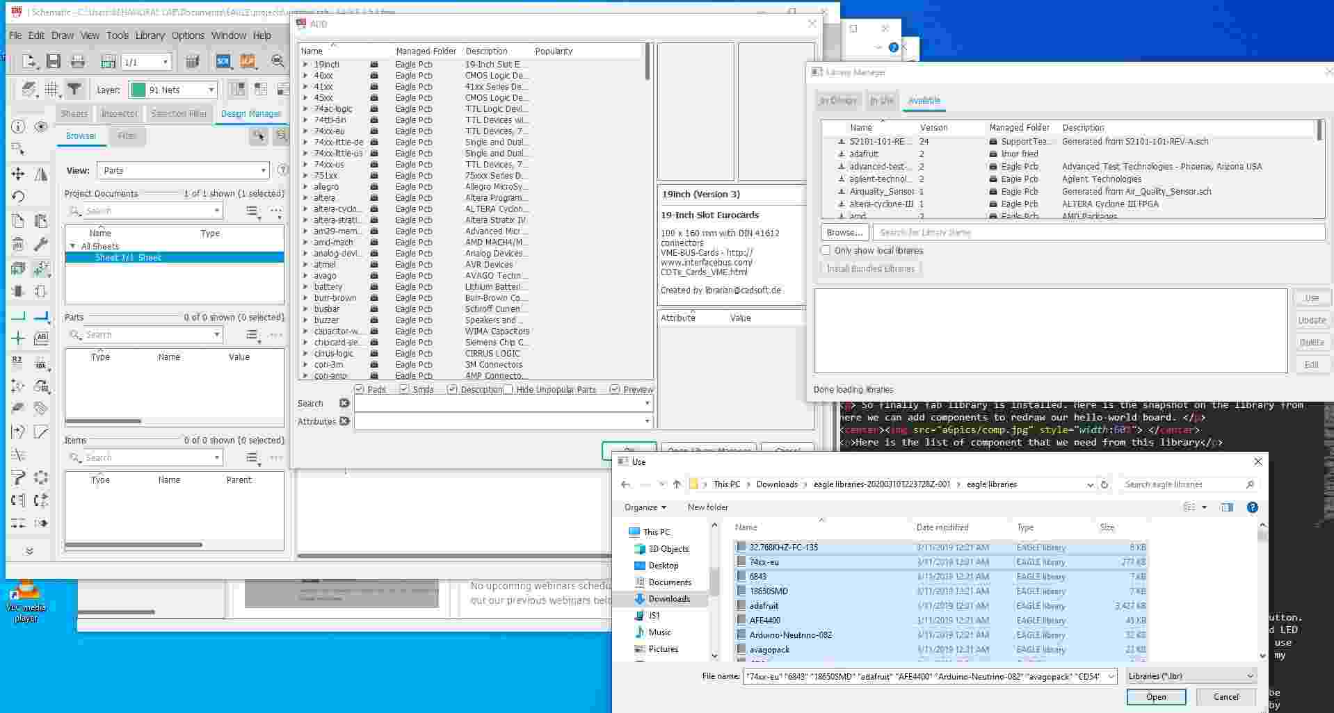
now its time to uplaod the Library first we goes to Select the Add part and click it,then open the library manager,than goes to Browser and Select the all Downloaded libraries and after press the use icon .
After This we Need to upload the ATTINY-44 Libraray in Eagle Software: Here
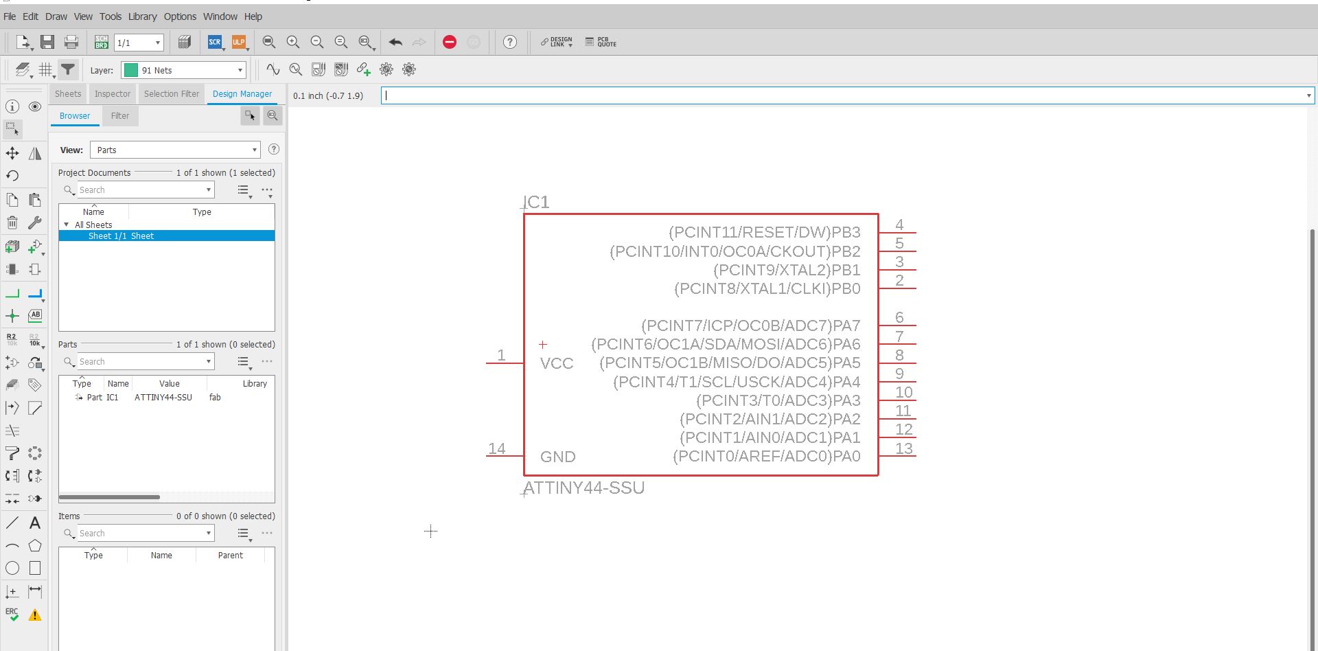
So finally fab library is installed. Here is the snapshot on the library , we can add components to redraw our hello-world board.So first add the Micro controller IC That ATTINY-44 in Eagle.
Instrcutions for the Eagle CADAfter exporting PNG our PCB layout is ready, Now we need to create its Board that will be used for milling machine to cut the required pcb from copper board. We can do this in Photoshop.
To create border image in photo shop we need to follow the following steps.
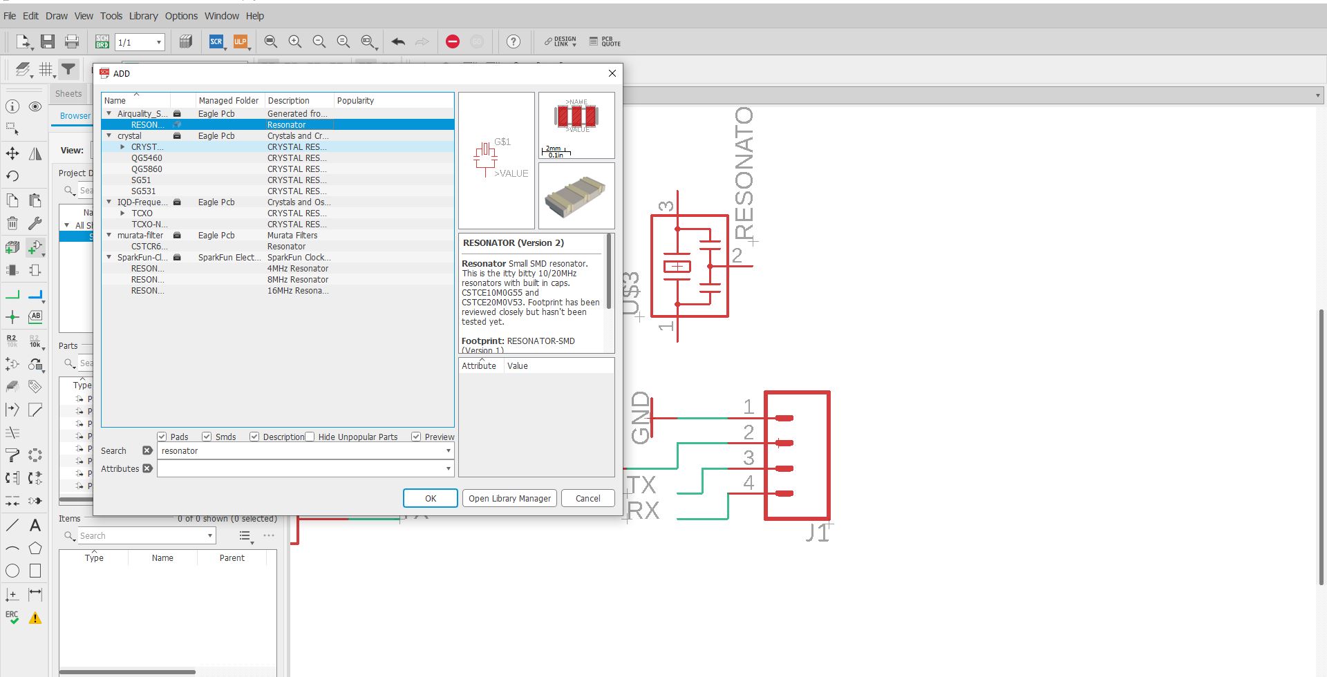
Now we can Add the resonator
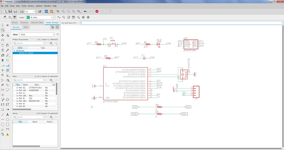
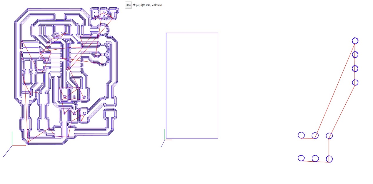
this is the final Circuit Board of Attiny-44
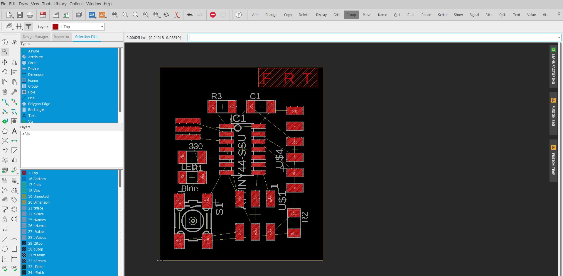
Now this layout is used for the routing and Placing the PCB Design
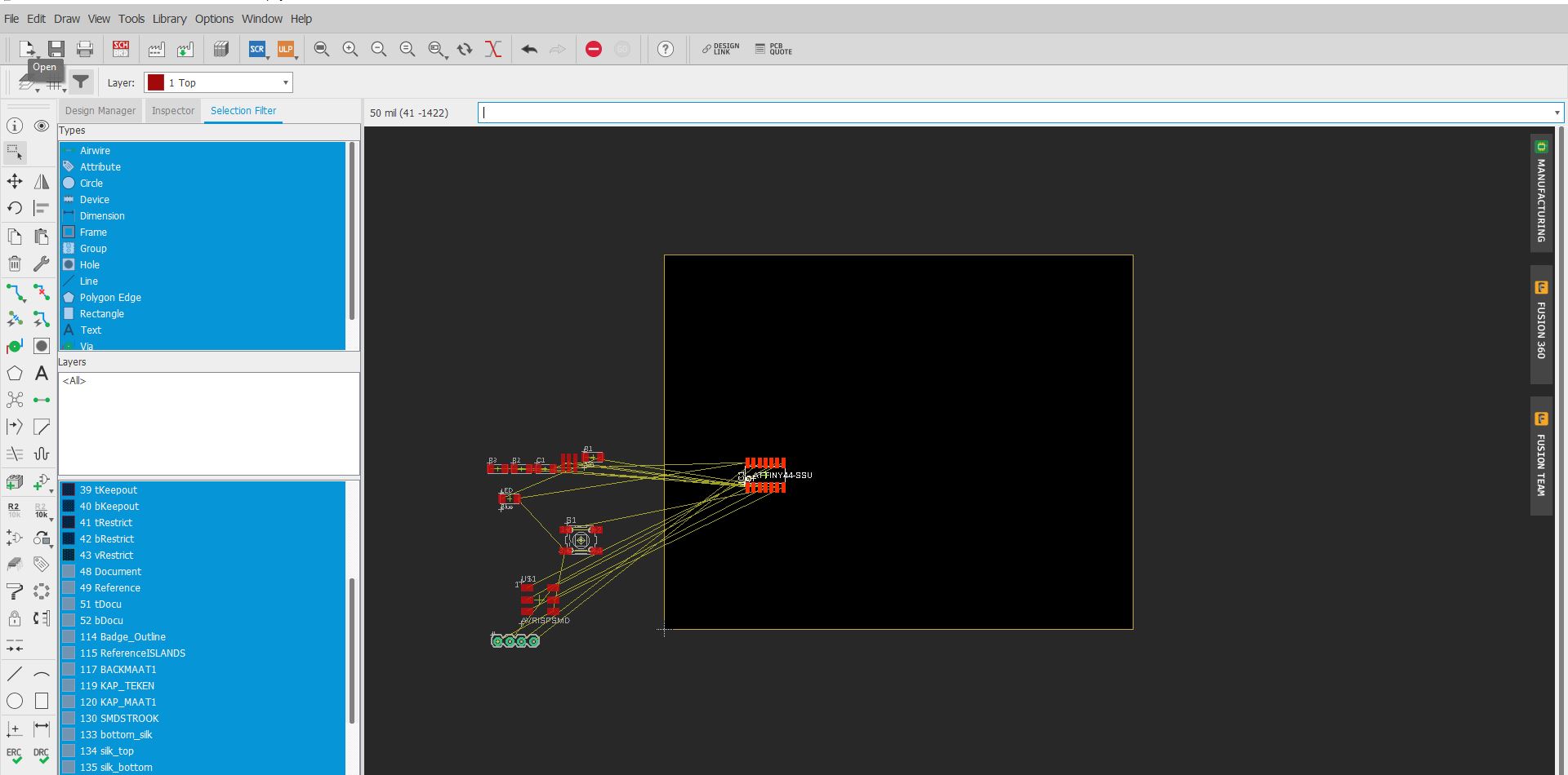
After above the process Now Placing the Components :Final View of Board
This is routing of Design the PCB,When the schematic diagram is complete we need to check the ERC (Electrical rule check), we can do this by using erc command. In my case I got zero errors and 5 warnings. All warnings are due to unused pins in the circuit. This step is shown here in the image given below
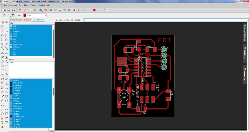
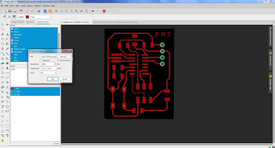
Now going to generate PNG file for the RML
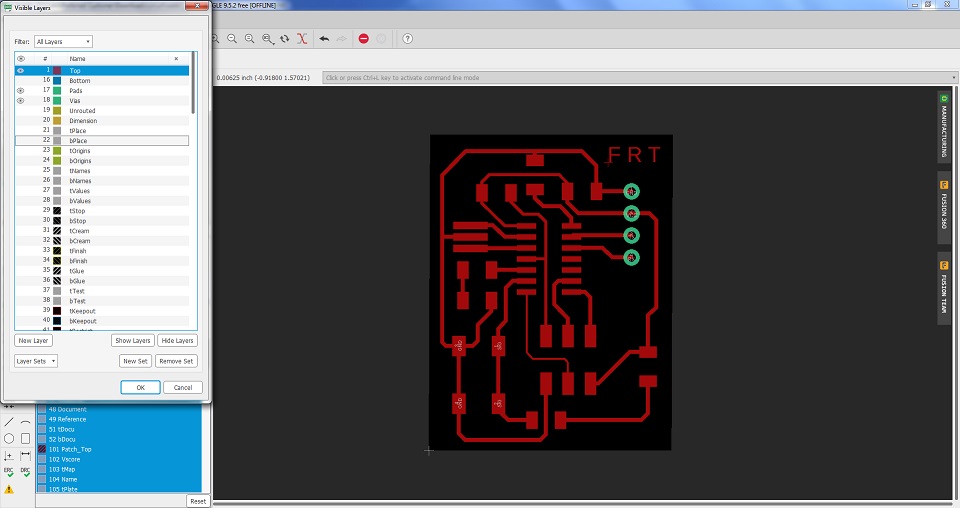
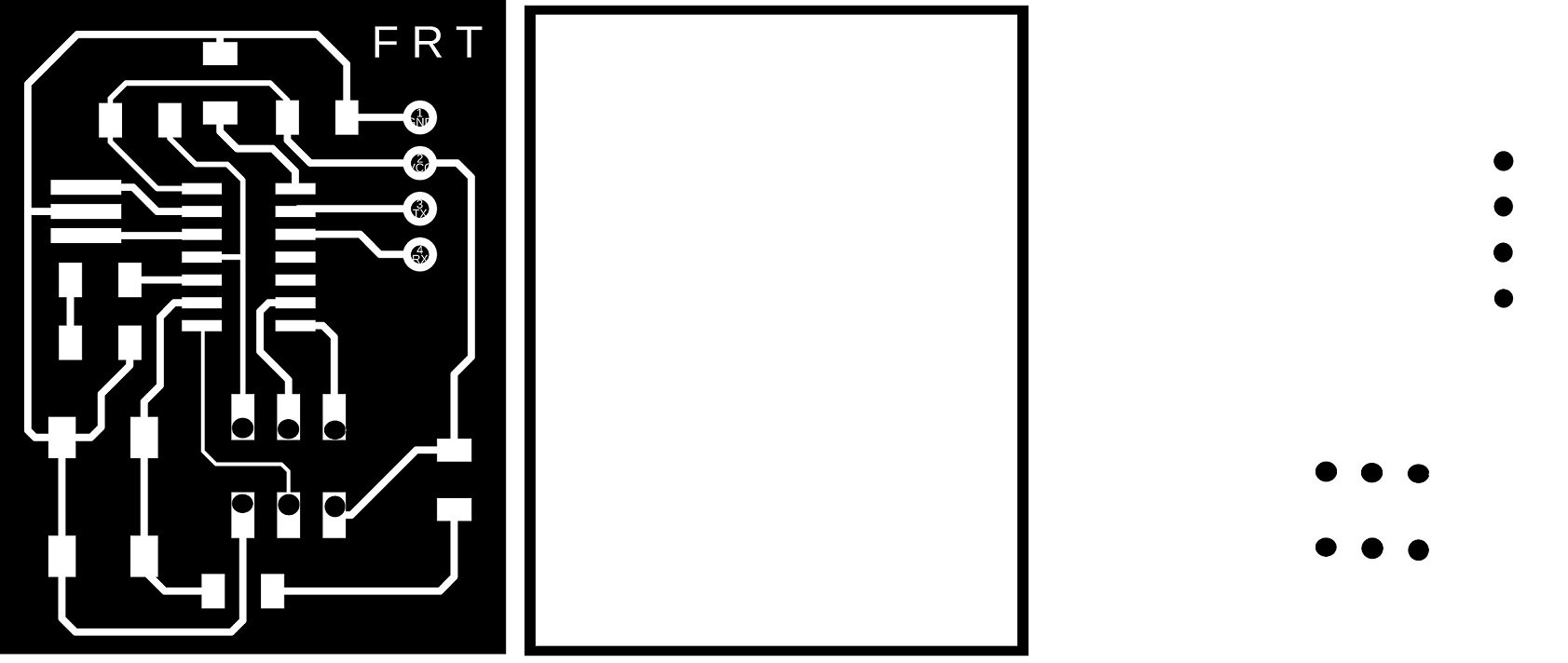
Now I am Going to Generate the Black PNG Image for the Milling
Now from the PNG Image I have to generate the outline and drill by Images in paint
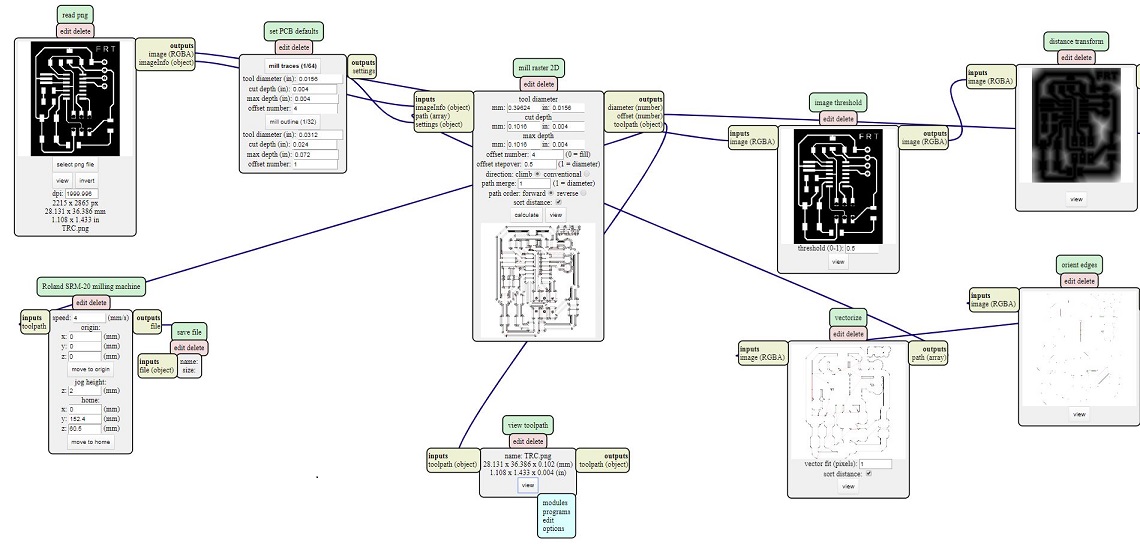
Now Generate the Traces by using MODS.
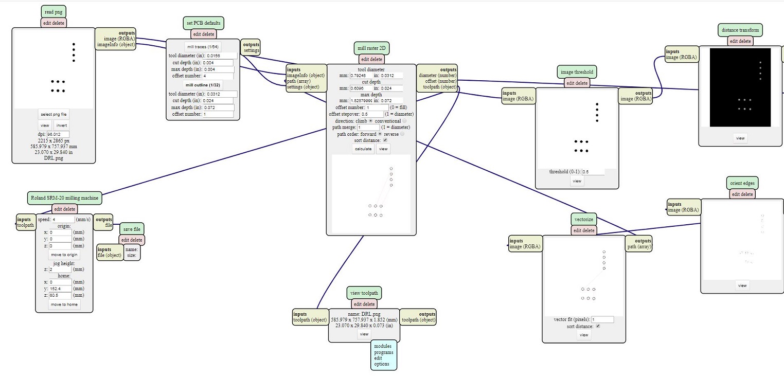
Now Again using the Mods to Generate the Drill and Outer
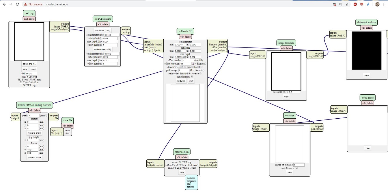
Now Again using the Mod to Generate the Drill and Outer
The Final rml results
Here is the list of component that we required for Soldering the PCB
After taking into account all the above consideration, finally I have complete my PCB layout ready of hello-world board. now going to miil ythe board by using SRM20, I ahve mentioned week electronics Production about SRM machine.
Steps Are given below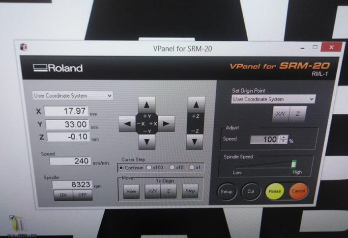
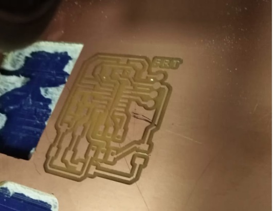
While Milling the Board
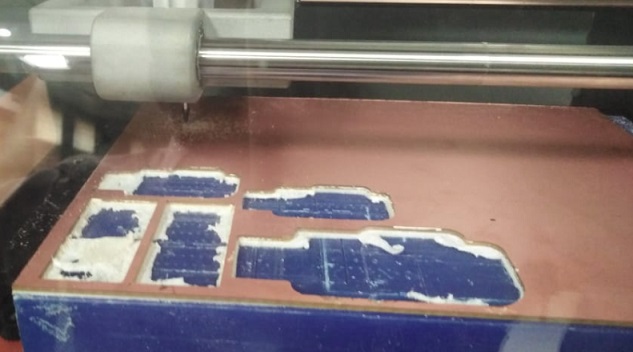
After the Trace Complete So Board is Looking:
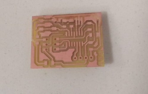
this the PCB Milling Board after the Drilling and Outerline :
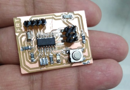
After the Soldering
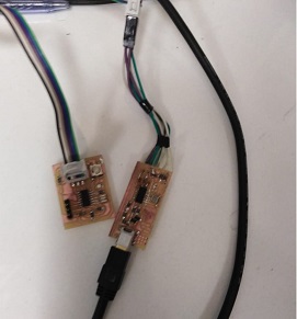
First Micro controller Board is Connected withe ISP-44 Programer for the Burn the Loader
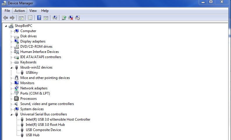
Further more Installing the drivers and test the ISP Programmer:.
So I need to install the drivers for the programmer. We can download from this site HERE
this the ISP-44 programmer and Mirco Controller Board Connections
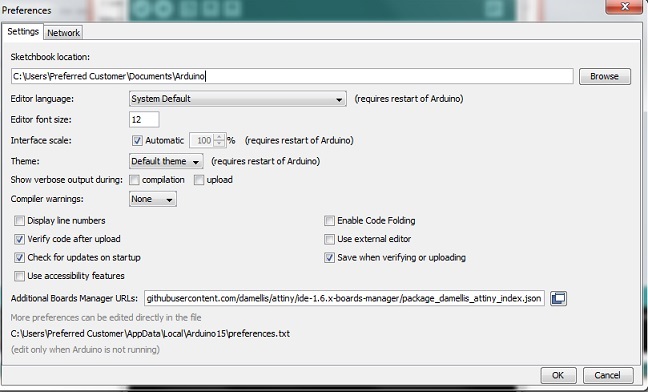
Now Downlaod the Ardiuno Ide and Install the in the Computer and also installed the ISP Programer drivers
Now open the Arduino ID and set the Preferences :
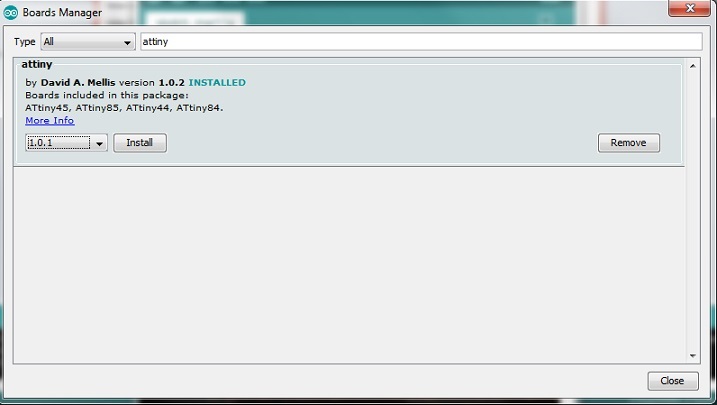
Now go to the Board Manager and update the Attiny Borad
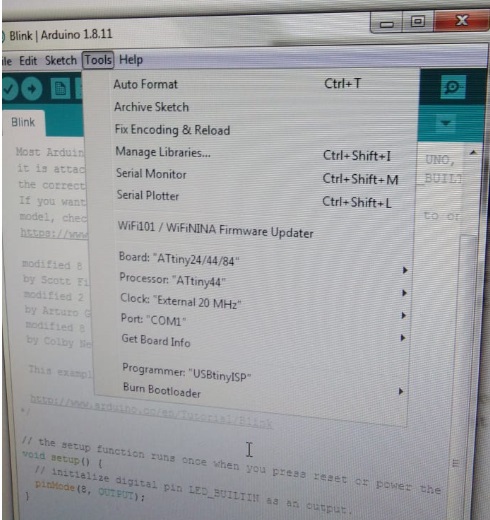
Now agian go to the Board Manager and select the Board attiny44/85/25 after set the Prcossor Attiny-44 and in last Select the 20MHz clock processor
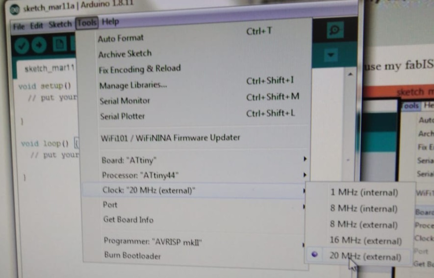
set the Setteing of the Processor
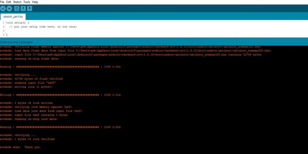
Now its time to burn the Bootloader
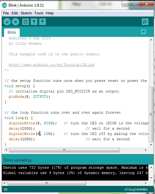
Now Upload the Program and check that Mirco Controller Board is working:
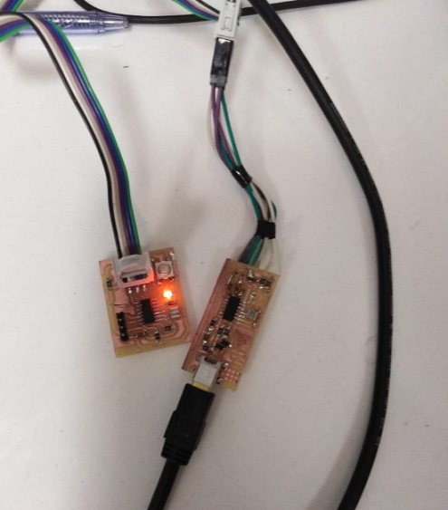
Final Results of the Attiny Mirco Controller after the Code burn so LED is Blinking
Group Assignments
Digital Meter testingAuto-ranging or manual-ranging Here the choice is a simple one: go for an auto-ranging digital multimeter since DMMs with auto-ranging cost about the same as DMMs with manual-ranging and the former is a lot less of a hassle to use and is more efficient when it comes to making measurements. The auto-ranging feature should also have a manual control override button so that you can fix readings to a specific range if the need arises. Finally, auto-ranging speeds need to be relatively quick so as not to excessively annoy the user - any multimeter that takes more than a second to auto-range is taking too long and should be avoided.
In this week we have planed for the Group task that we will used the Digital Meter to measure the Resistance , capictance ,Volatge and connectivity and much more.
first we have Check the Meter , that is working or Not so its Working

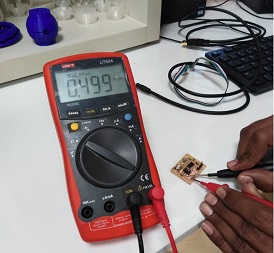
Now check the resistnace in Board using Meter
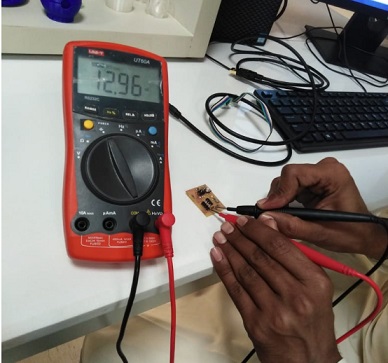
Now we want check the Value of capacitor.
after that check the Connection Conectivity
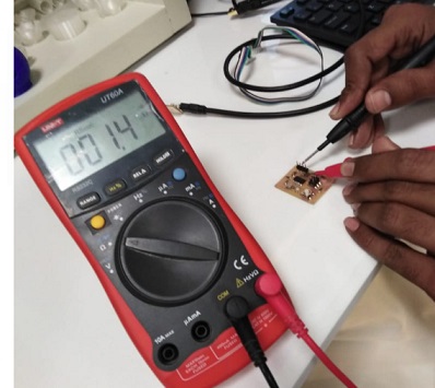
volage Across USB that 2.2v or 3.3v
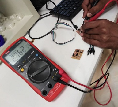
Final Volage arcoss the Attiny- 44 That is 5v
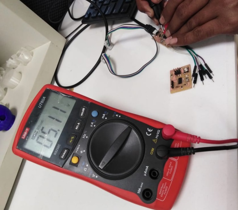
Using multimeter we observe the operation of microcontroller. We observe the volatge at digital pins as well as volatge drop at power supply. This help us to undestand that digital pin gives 5v output so we can drive any output device having 5v rating. But microcontroller has low current output at digital pins so we can not drive directly any high current rated device directly from microcontroller.
Conculsion
This week was intertesting and Learning week for the Electronics Designed, I have used the Eagle CAD Software ,Embedded system Programming , also used the C++ for the Programming.Finally i have done the Good Job regarding the equipments testing and other Electronics Lab use.
Download all files from here

This work is licensed under a Creative Commons Attribution-NonCommercial-ShareAlike 4.0 International License