Week 13
Moulding and Casting
Objectives
Individual Assignment
Group Assignment
Learning Outcomes
Individual Assignment
Casting is a manufacturing process in which a liquid material is usually poured into a mould, which contains a hollow cavity of the desired shape, and then allowed to solidify. The solidified part is also known as a casting, which is ejected or broken out of the mould to complete the process. Casting materials are usually metals or various cold setting materials that cure after mixing two or more components together; examples are epoxy, concrete, plaster and clay. Casting is most often used for making complex shapes that would be otherwise difficult or uneconomical to make by other methods
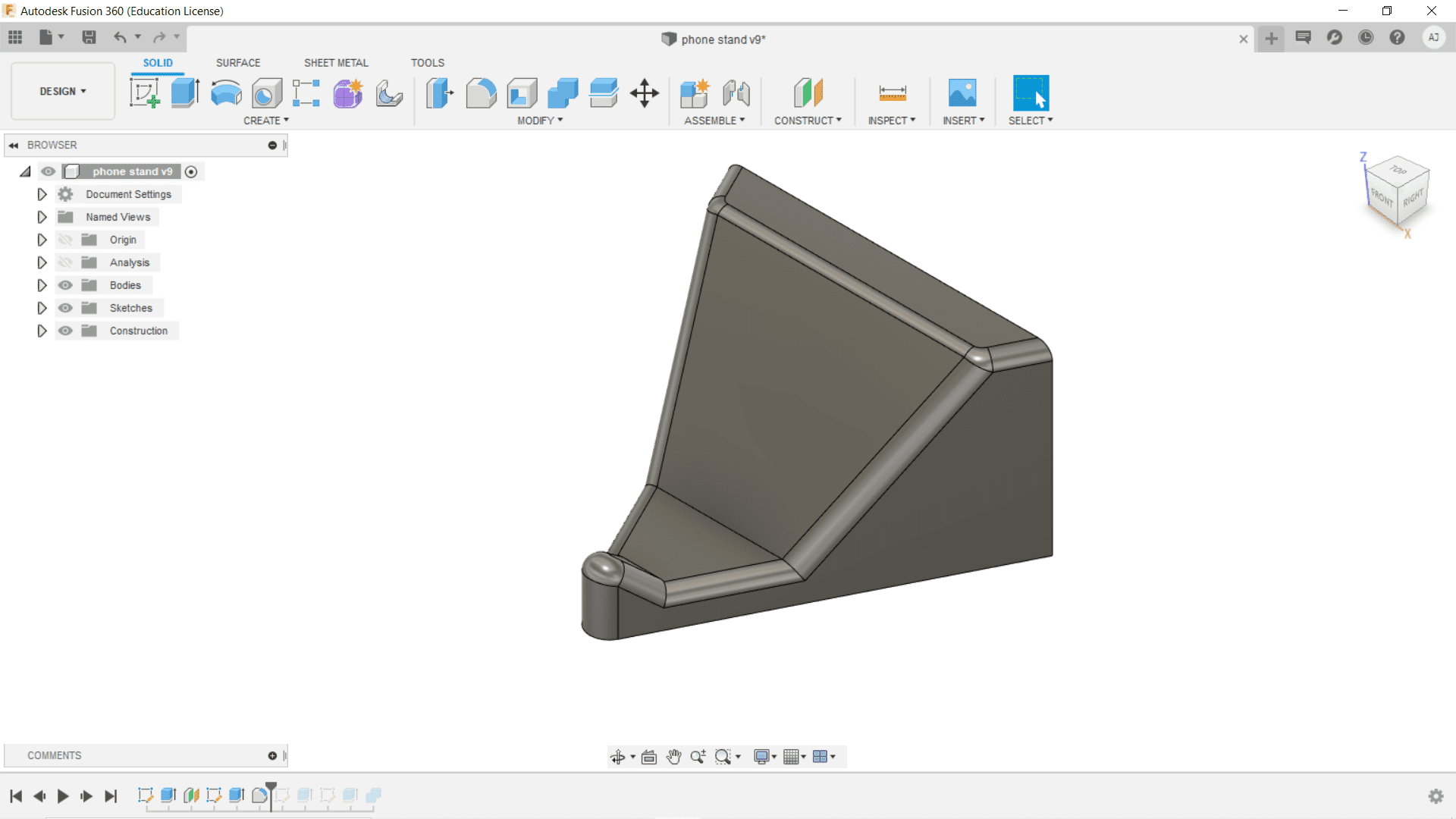
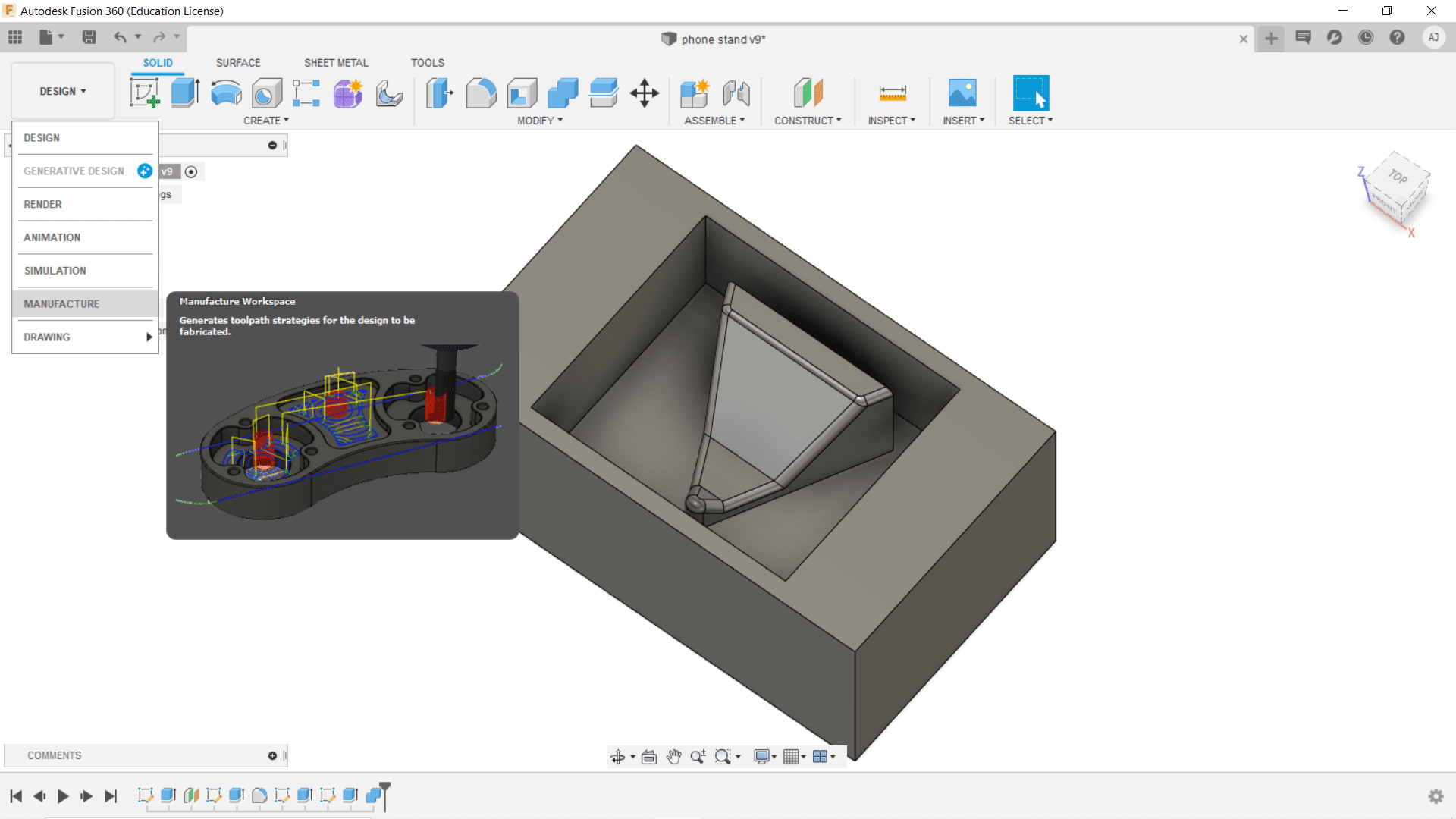
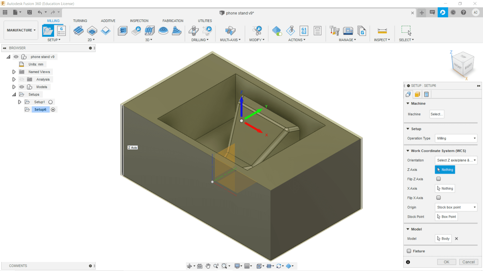
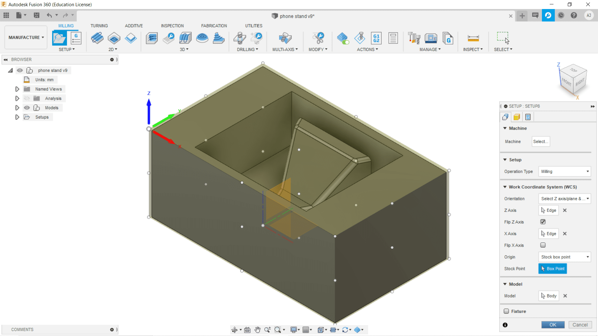
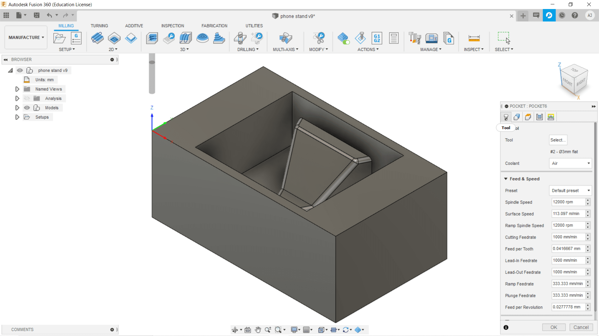
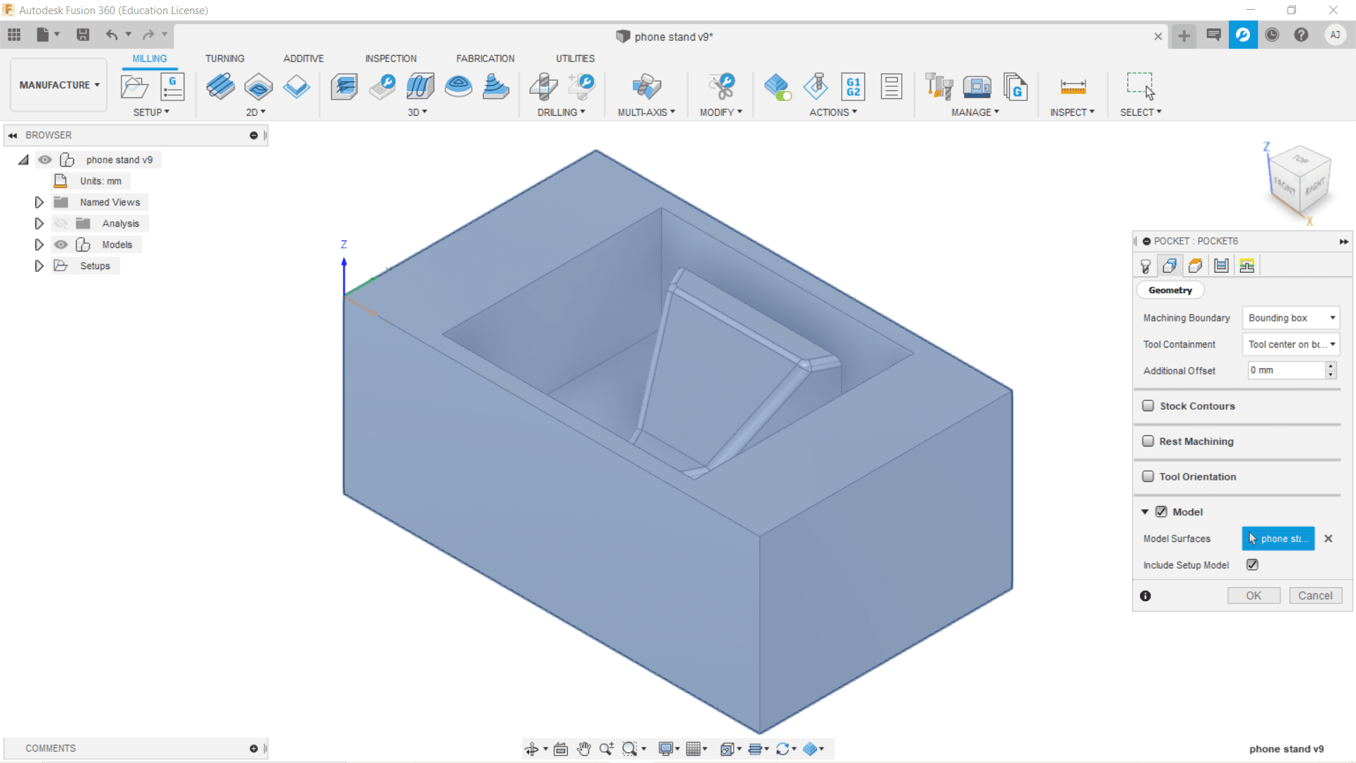
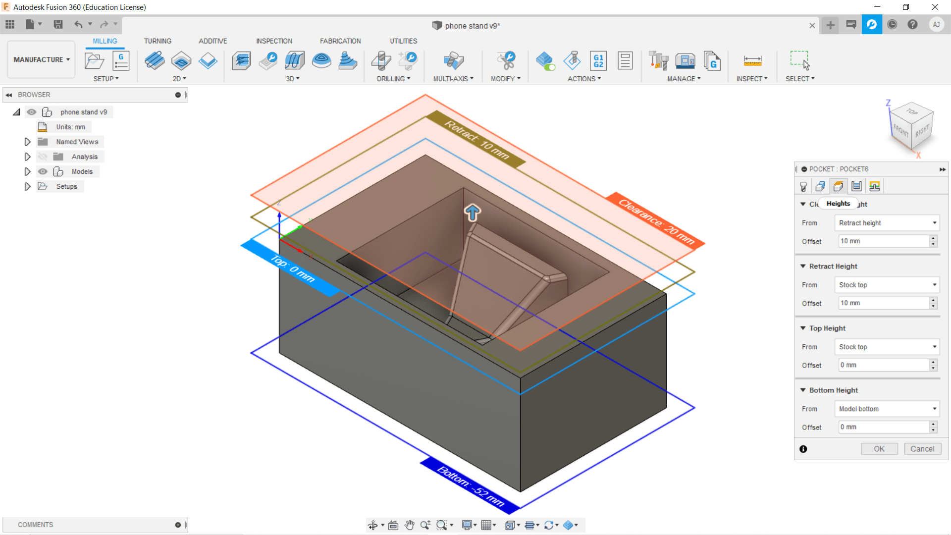
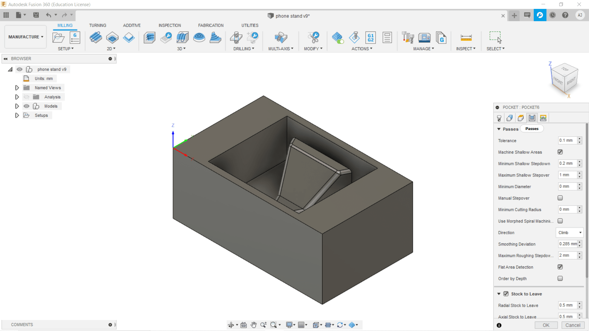
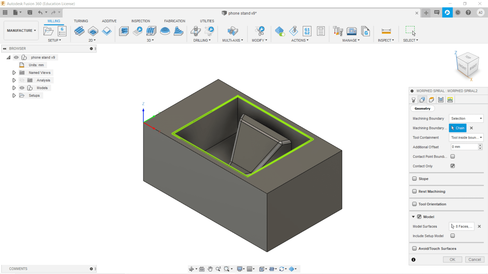
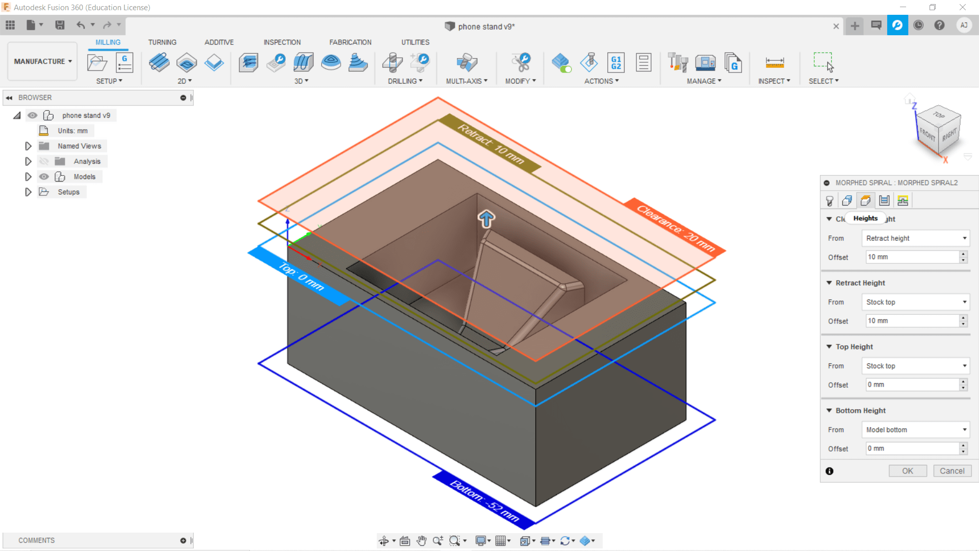
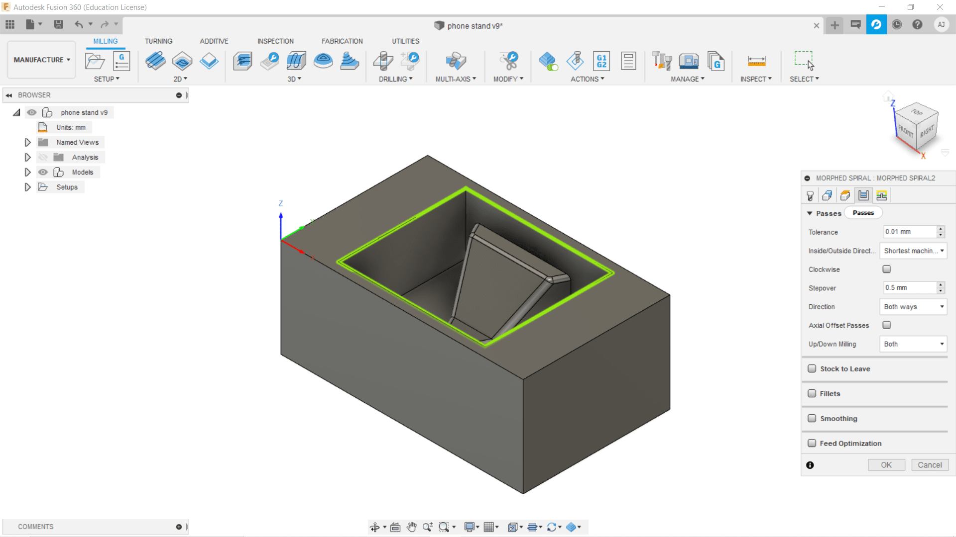
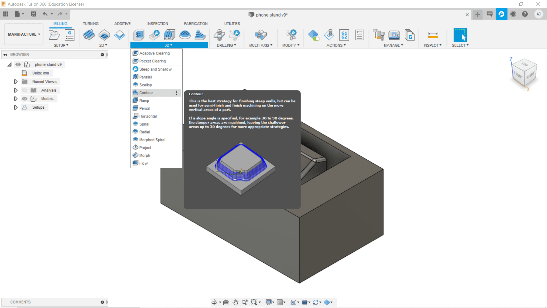
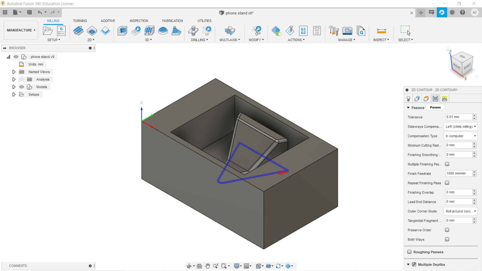
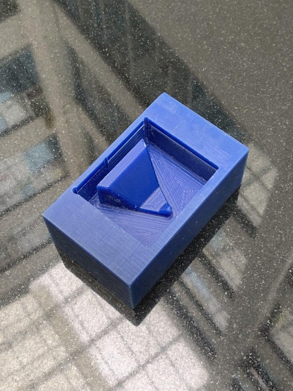
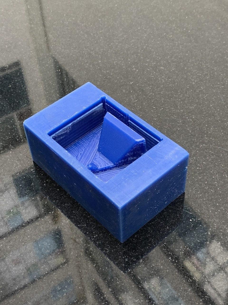
3D Mould Designing
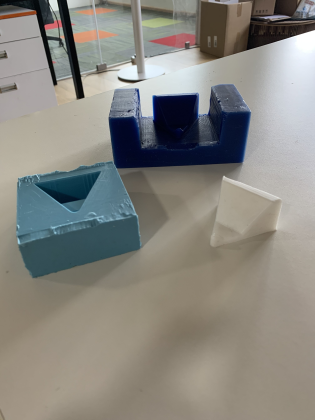
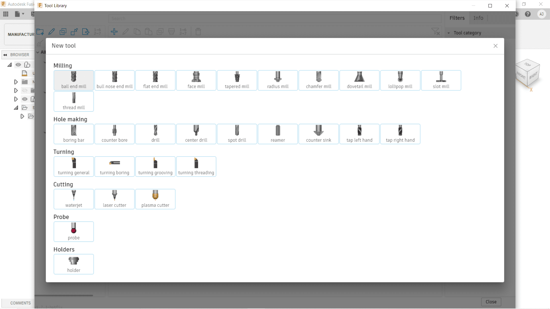
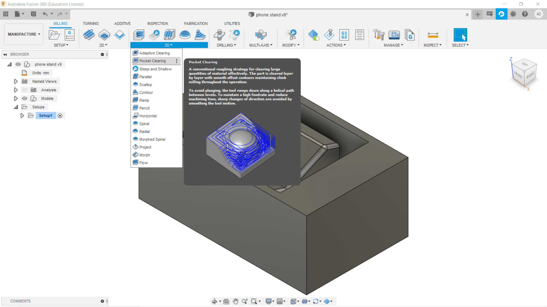
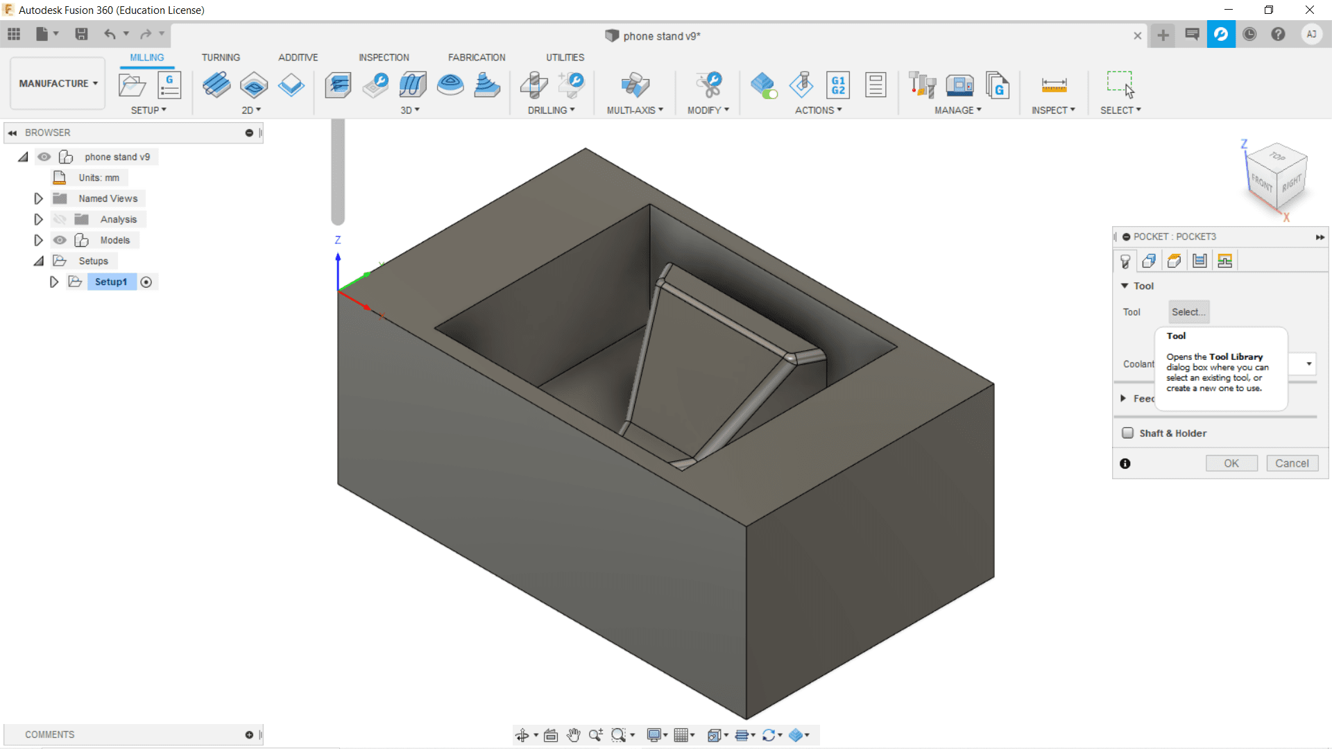
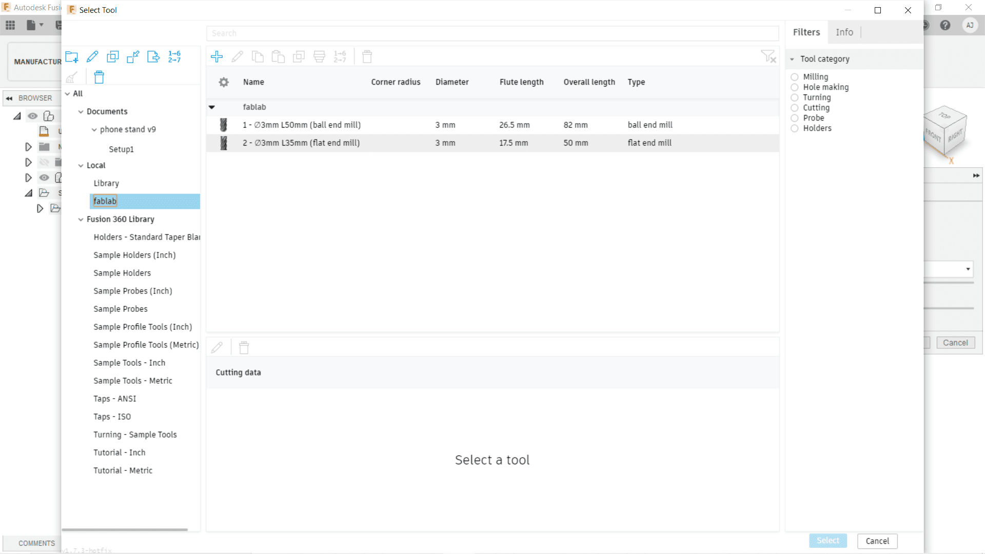
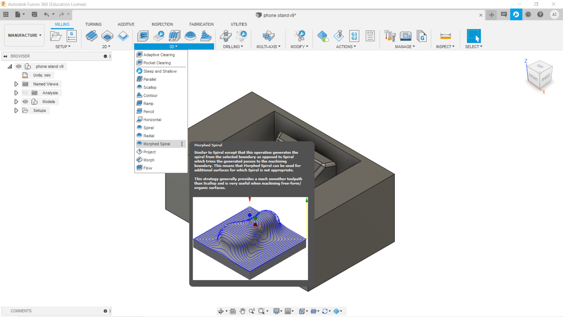
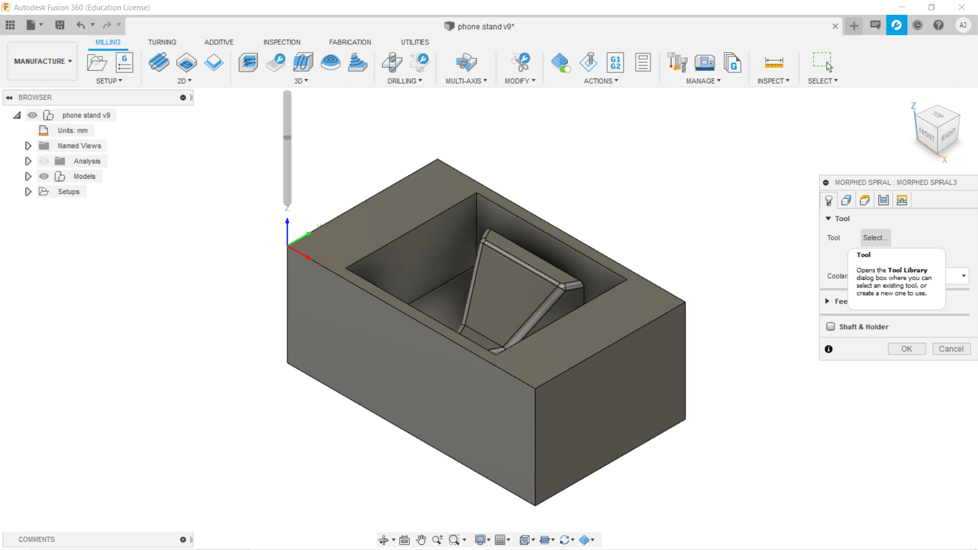
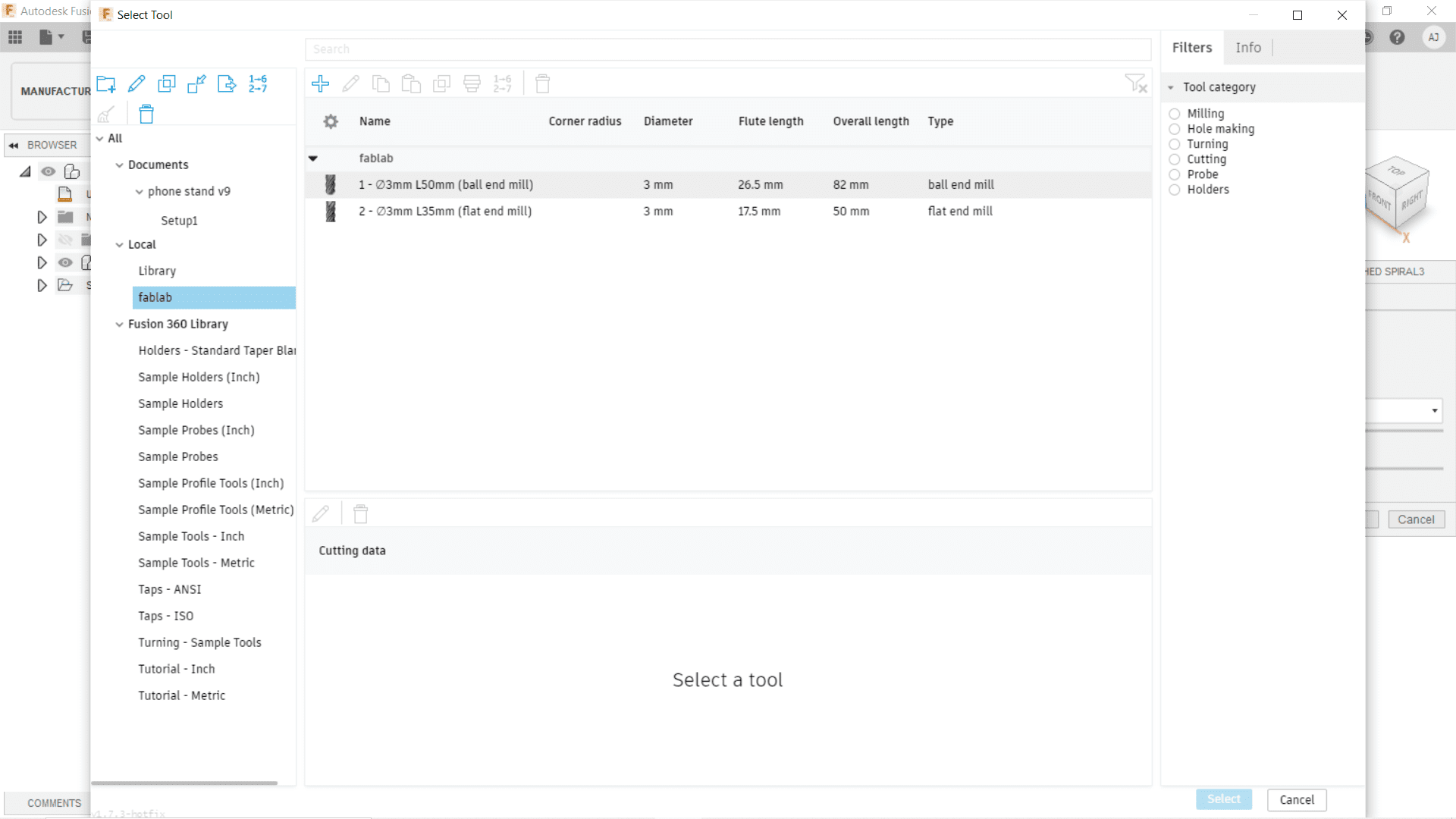
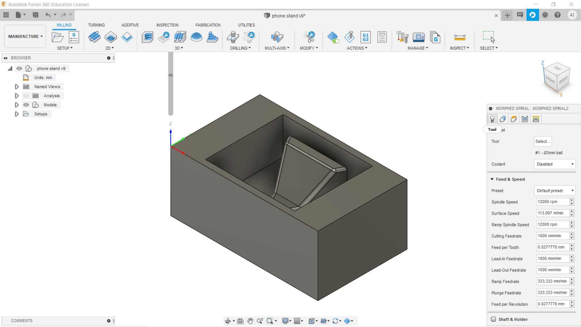
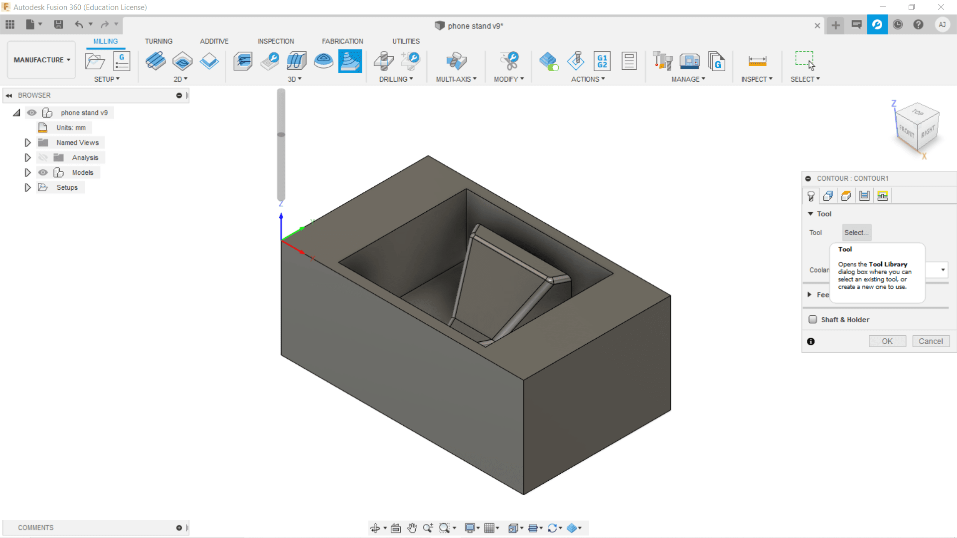
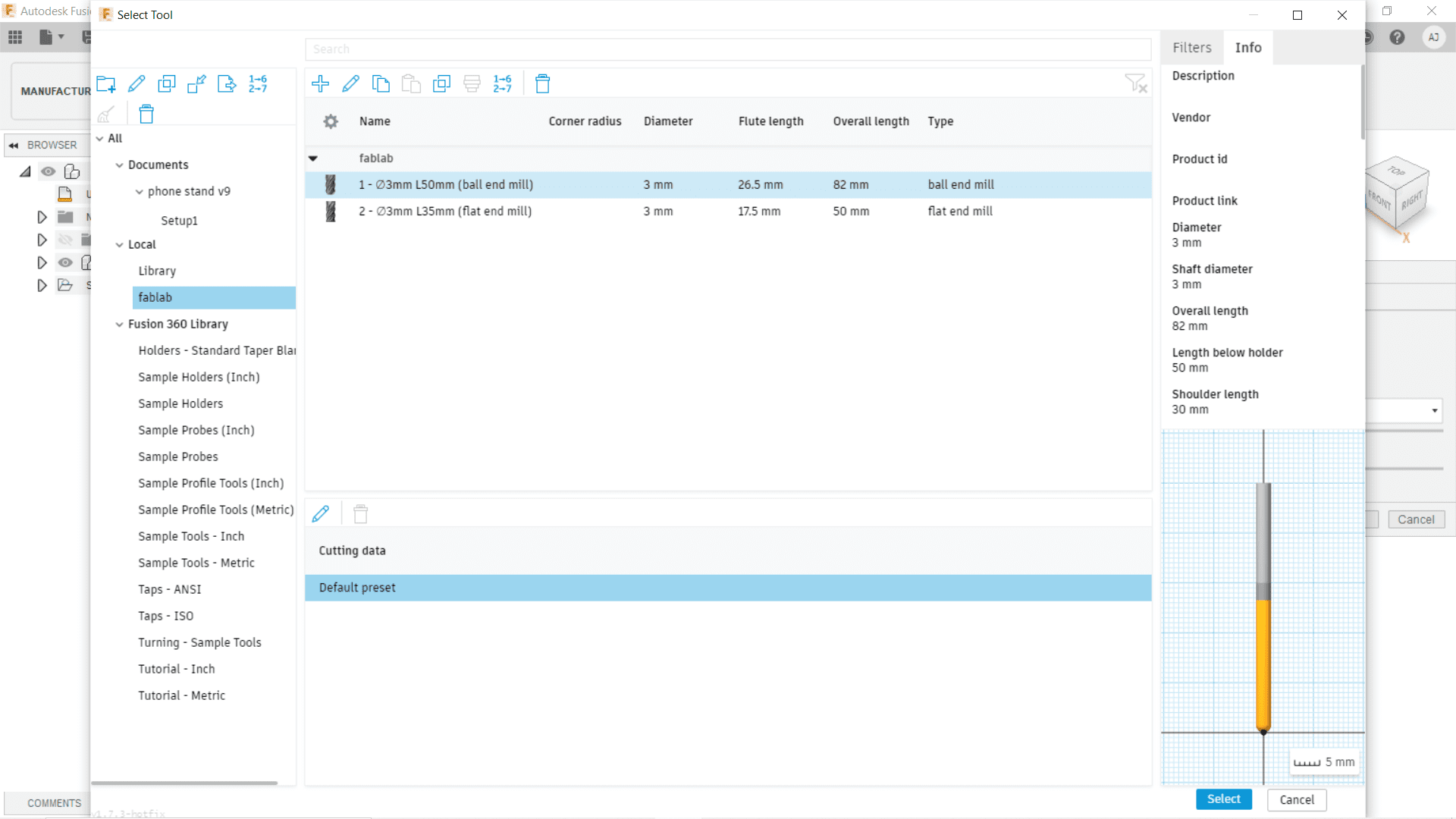
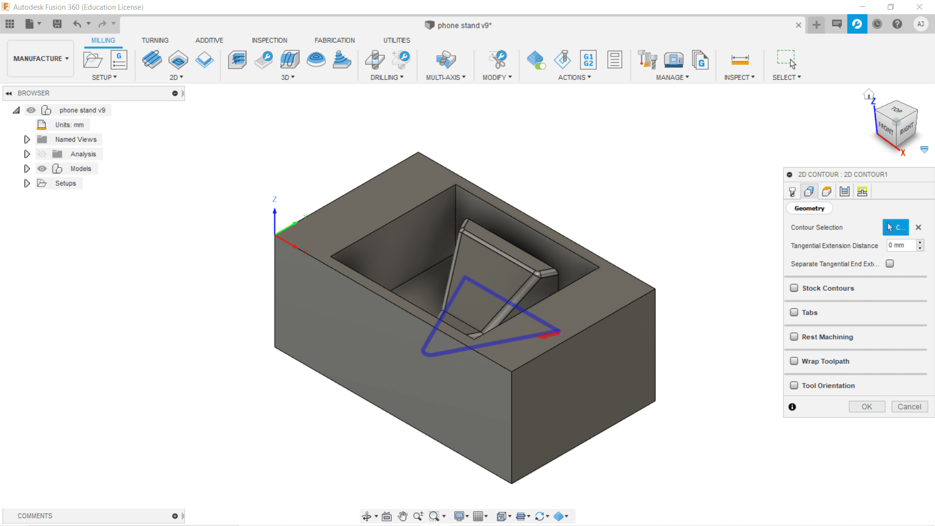
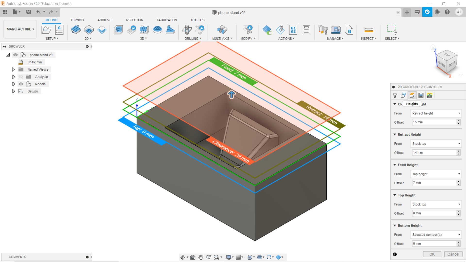
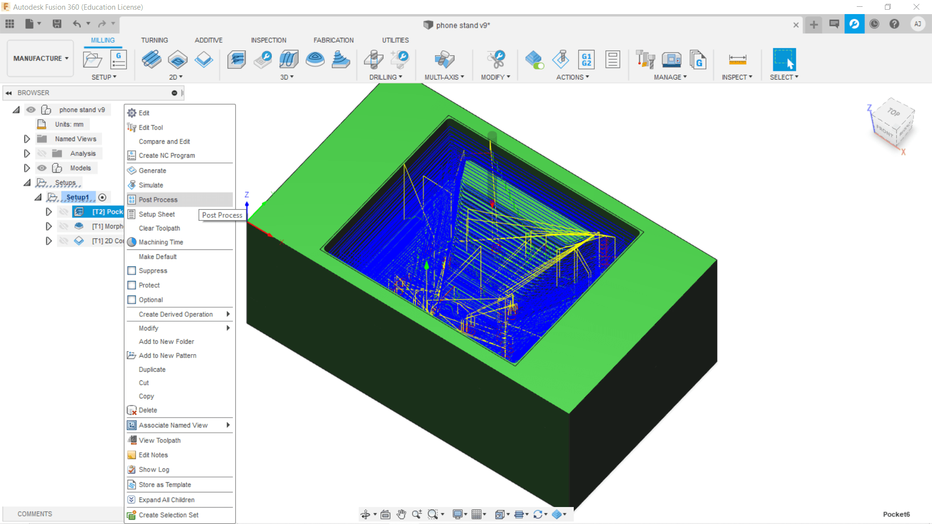
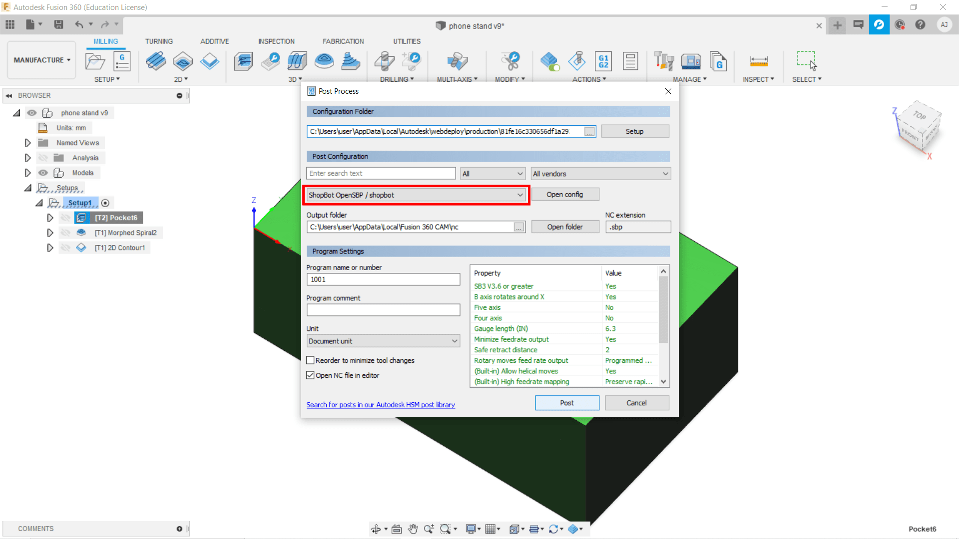
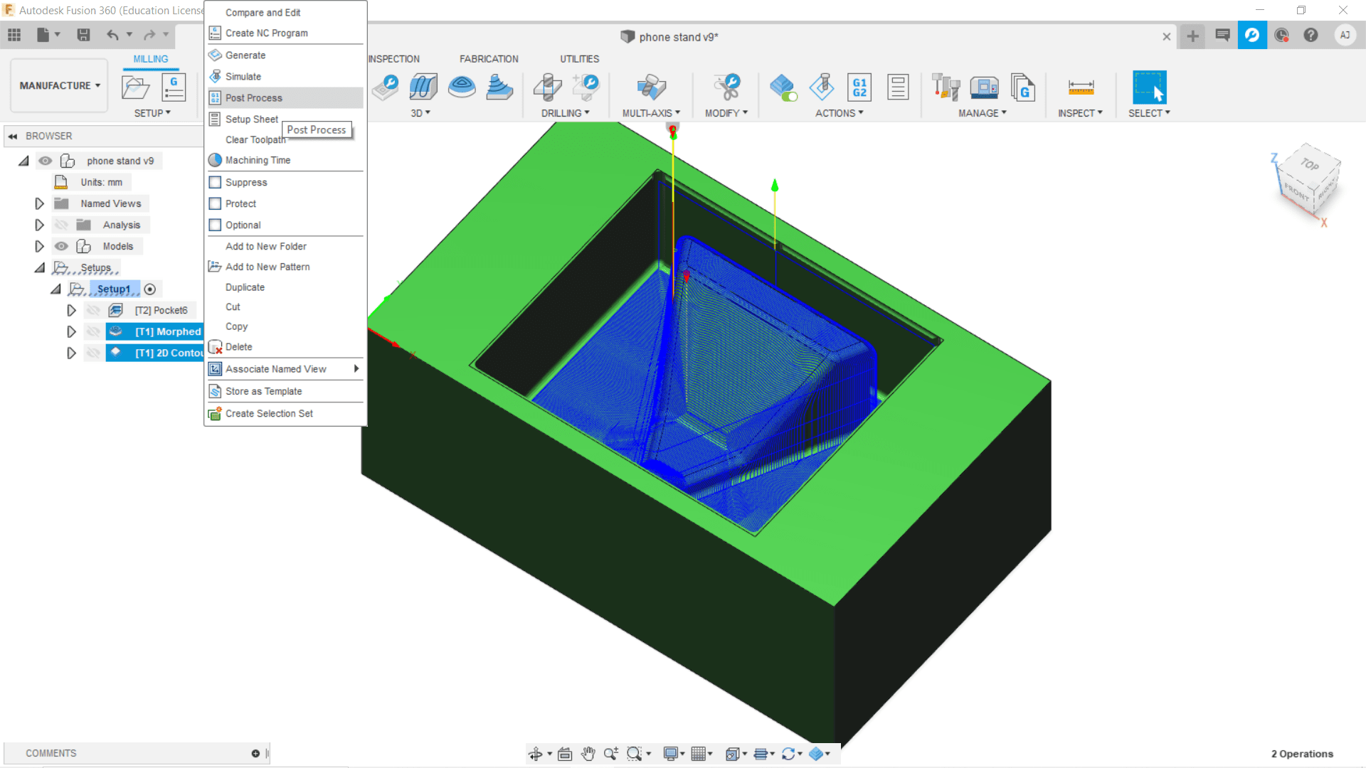
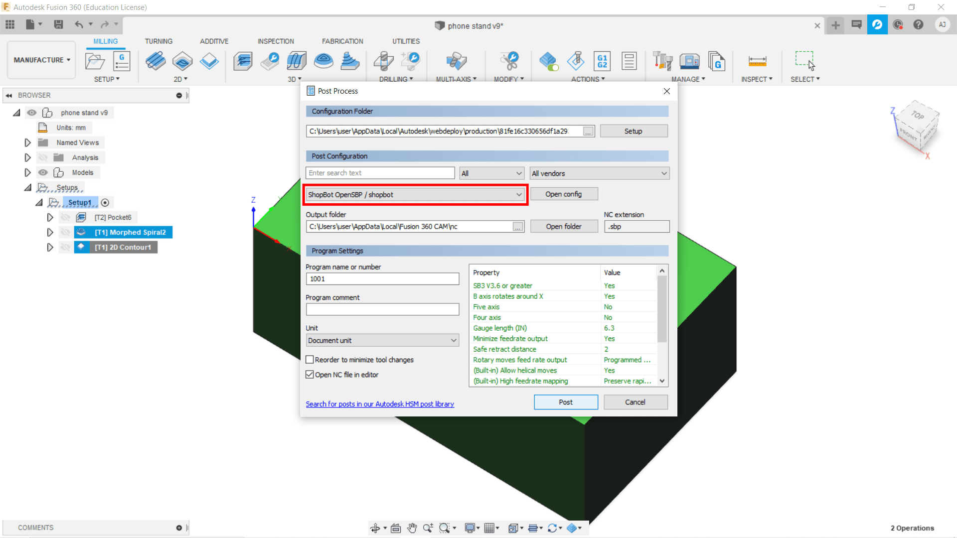
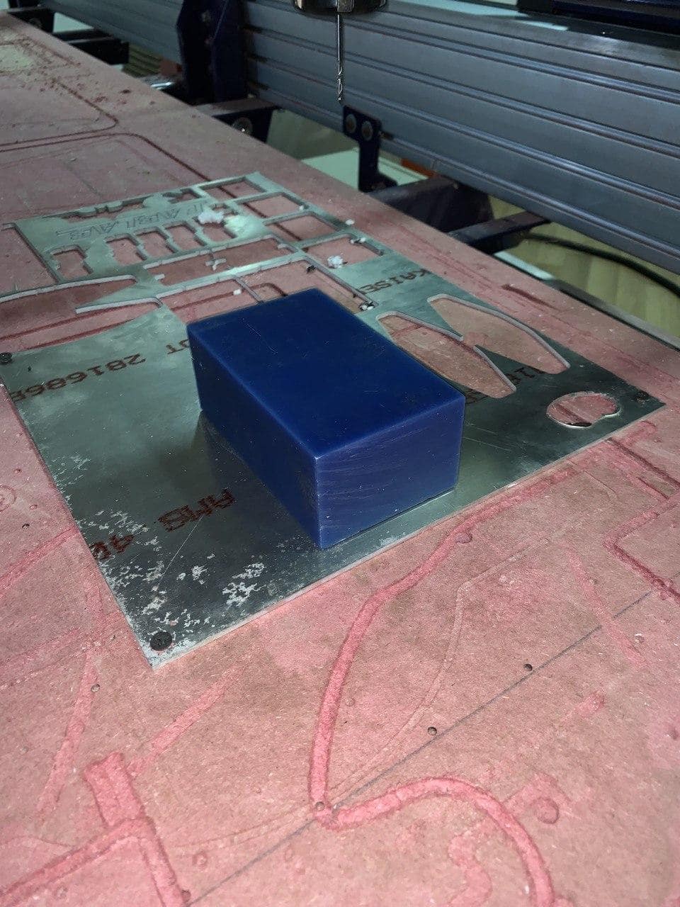
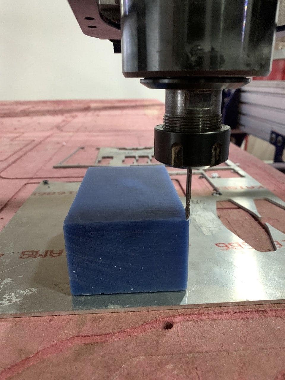
Mould Making
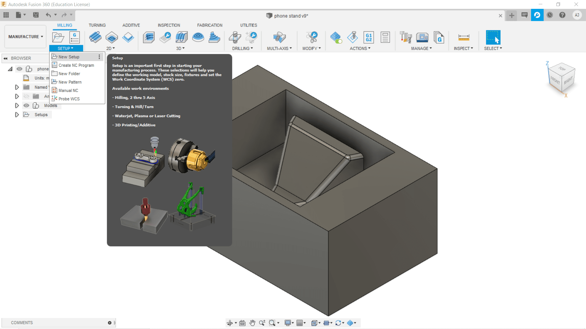
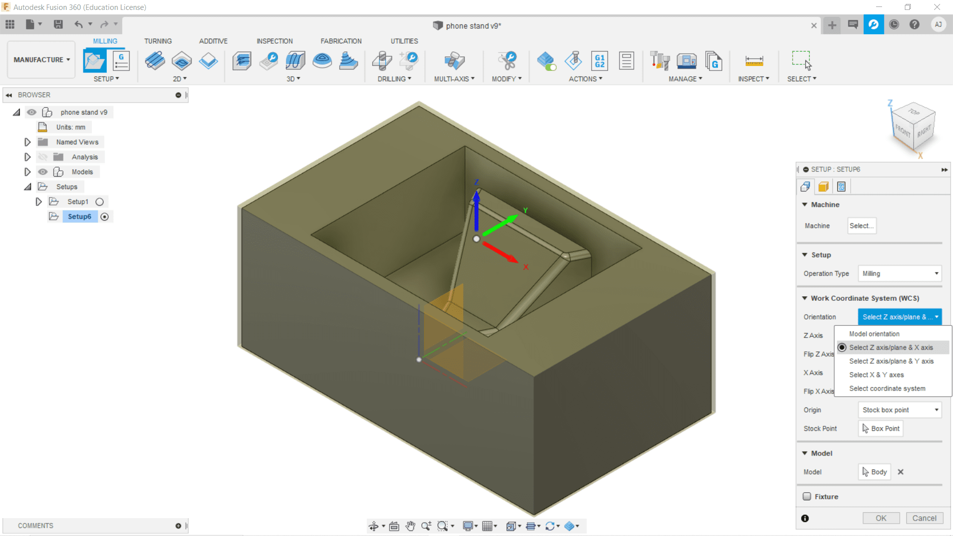

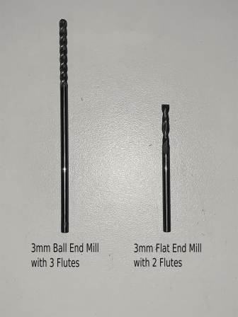
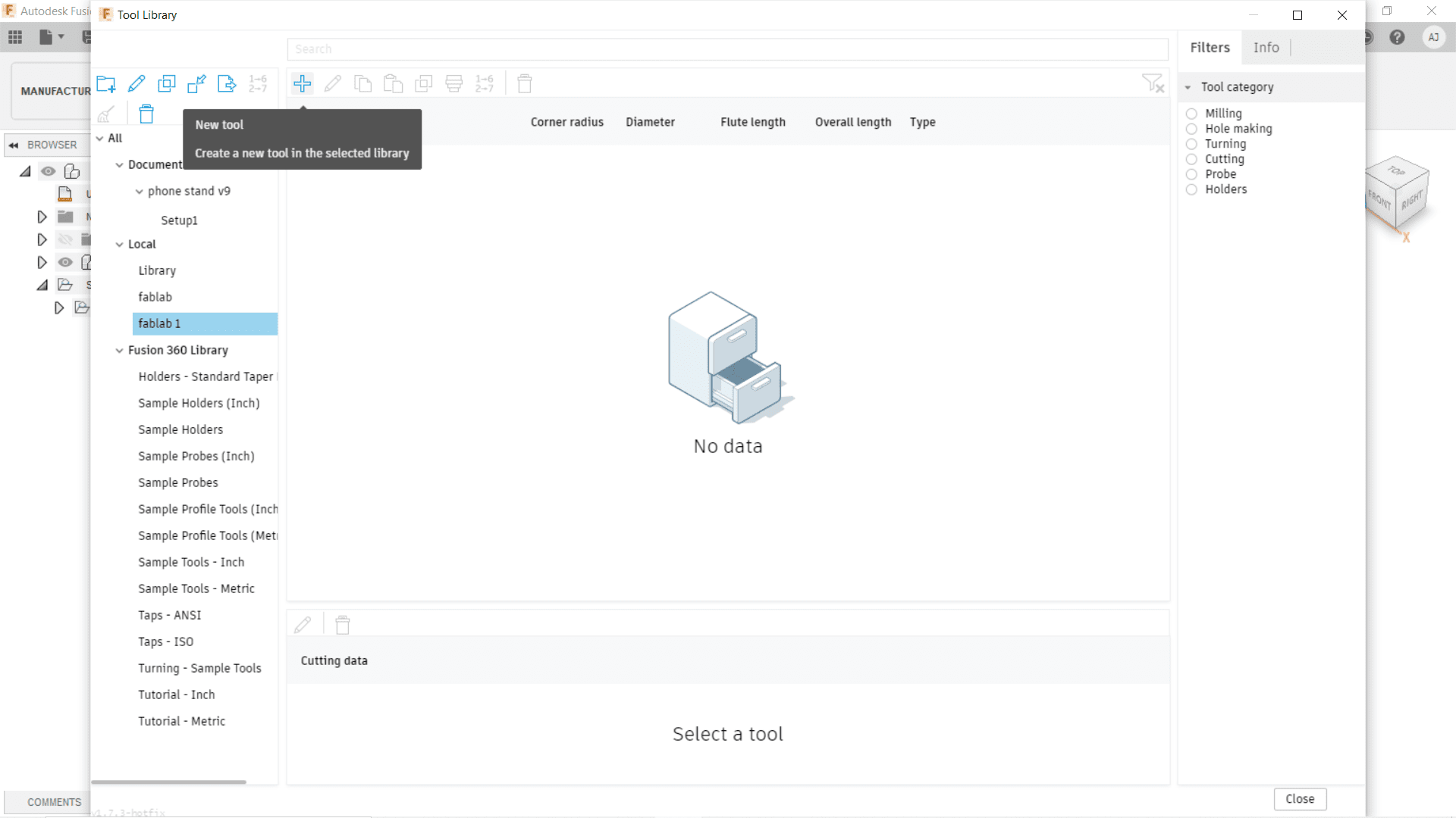
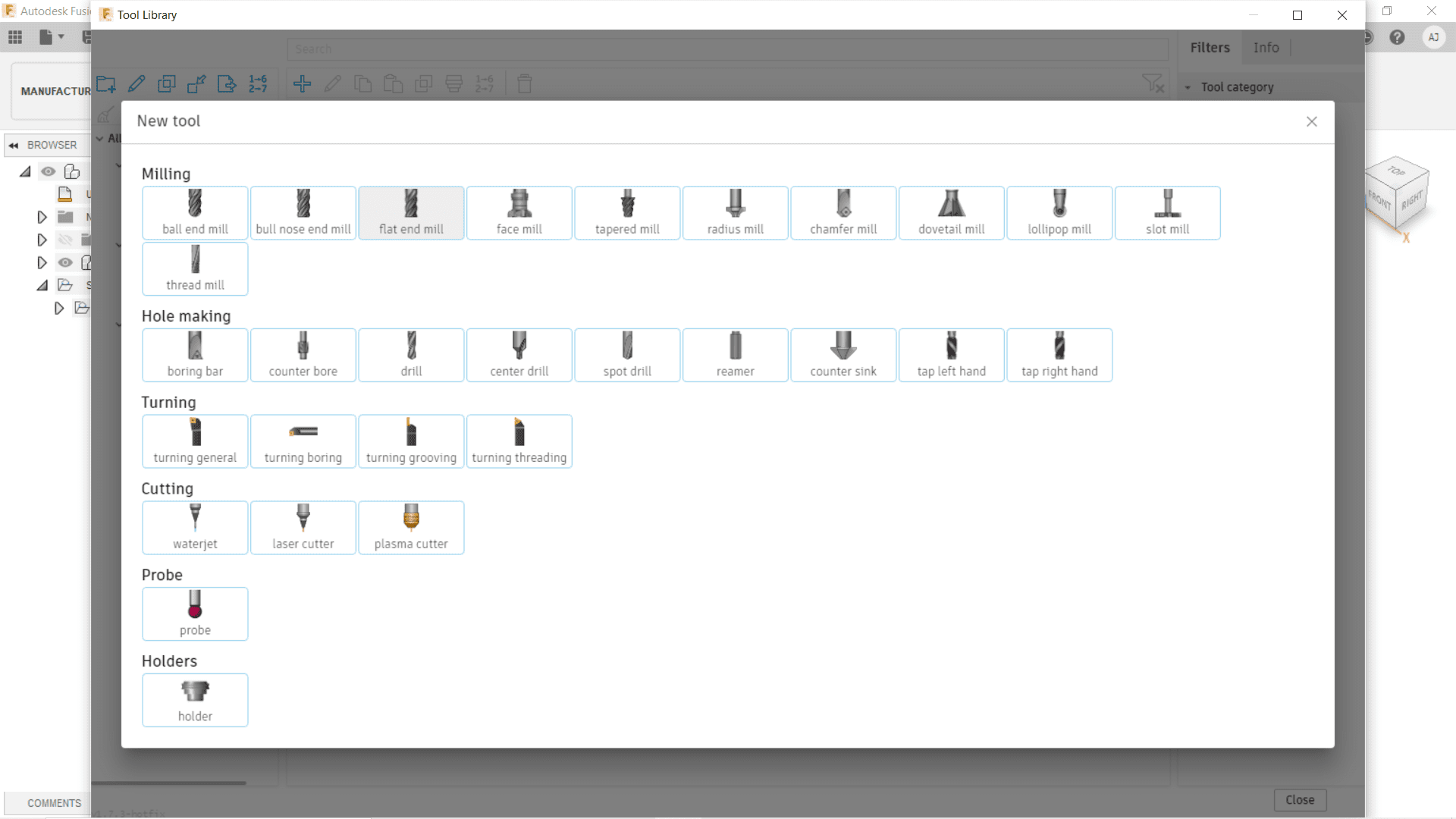
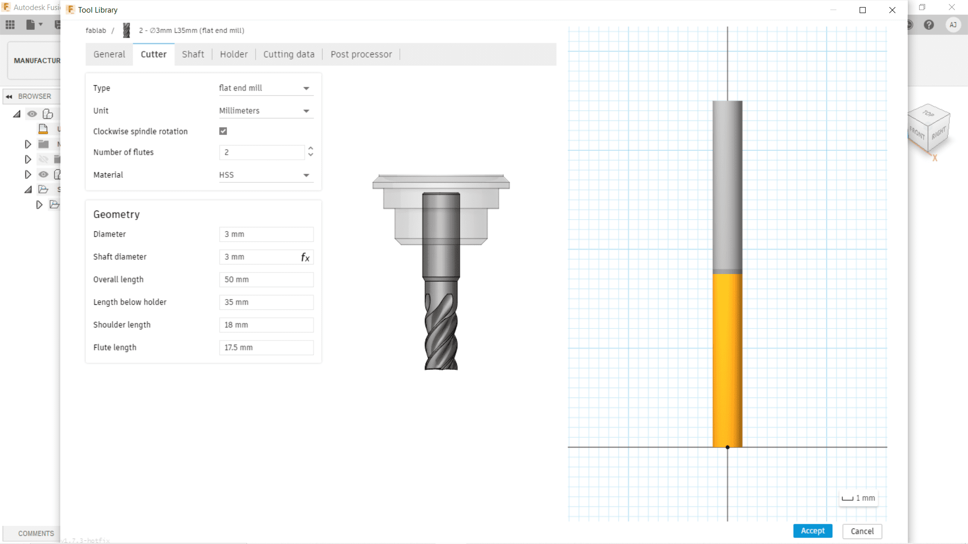
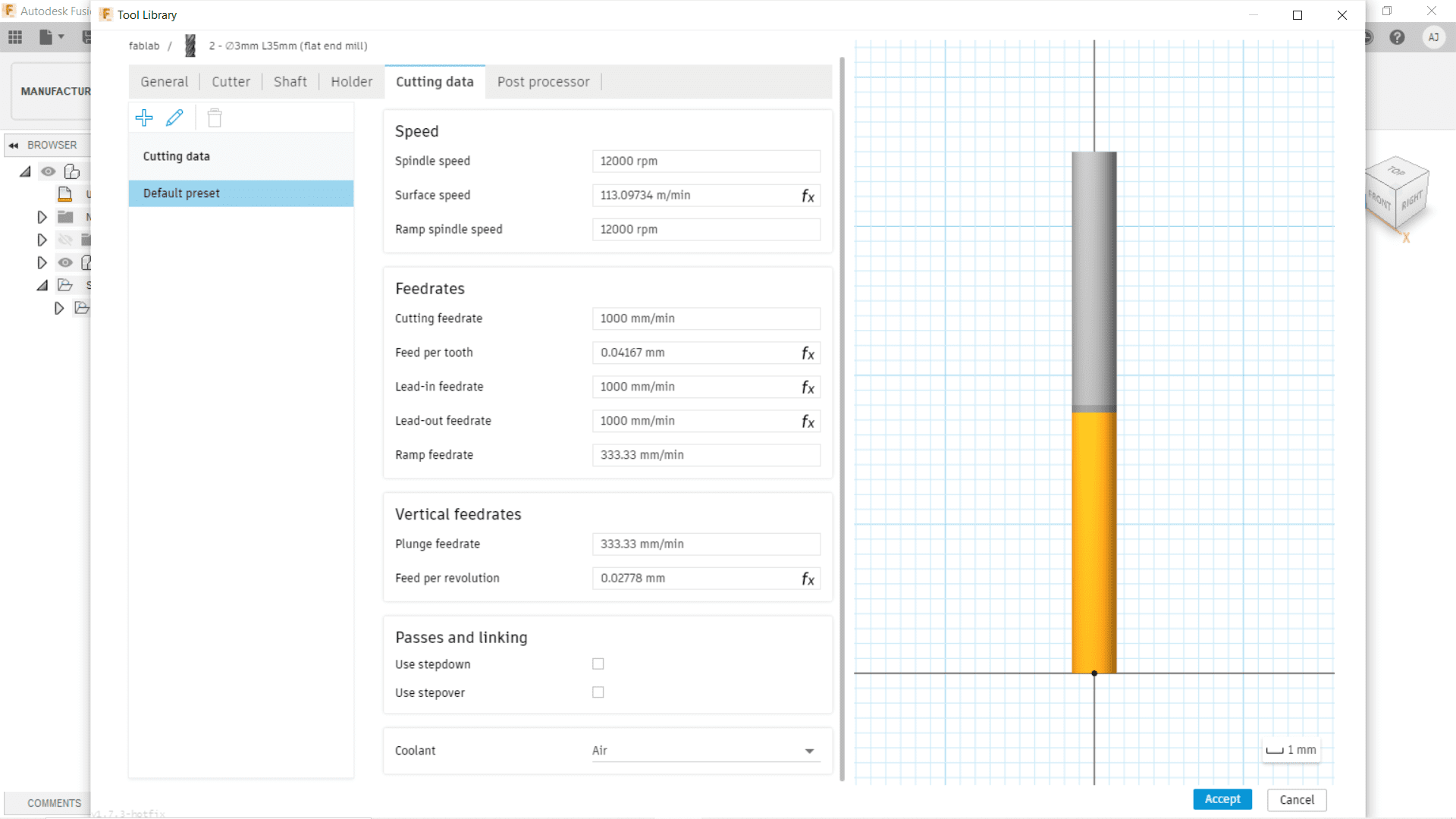
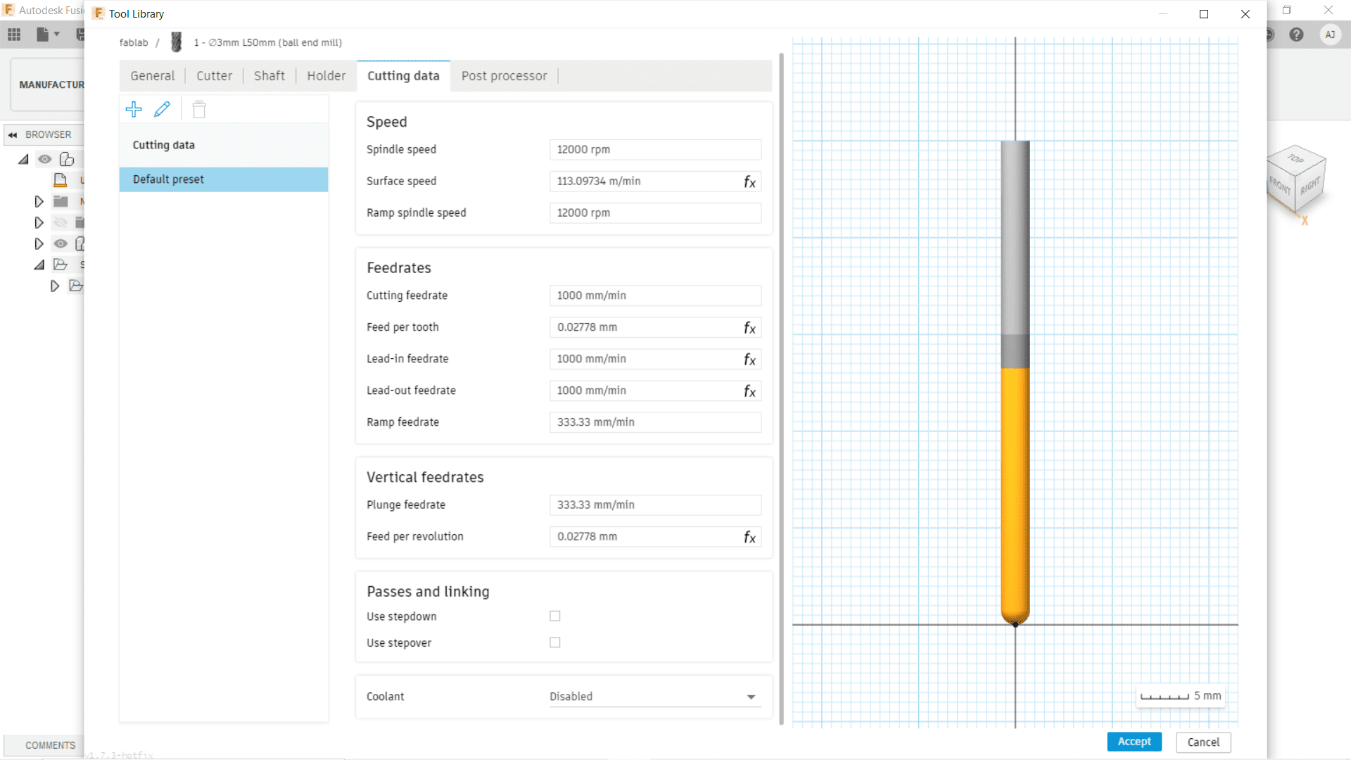
To set the Ball End Mill parameters into the software repeat the same steps as follows.


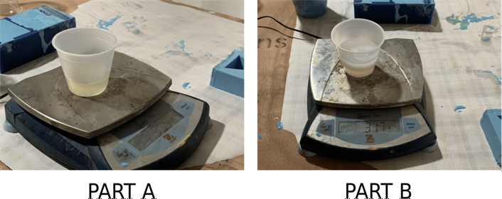
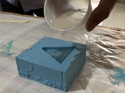
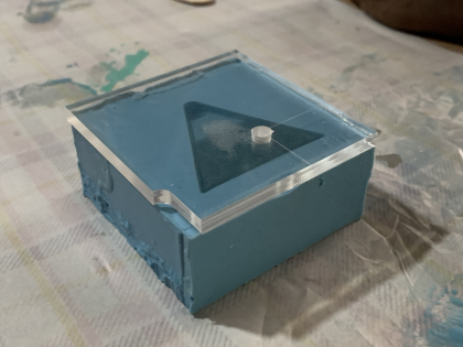
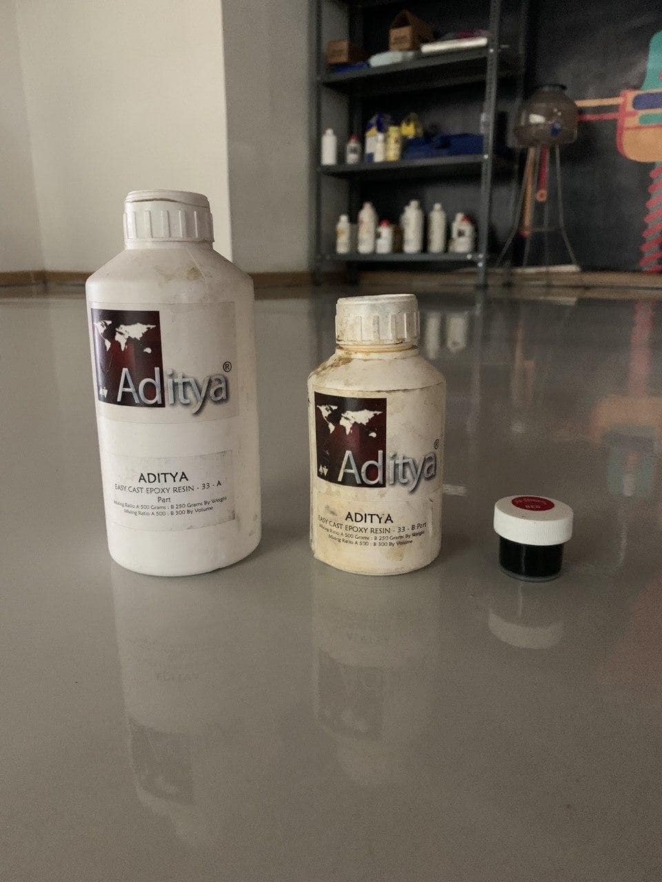
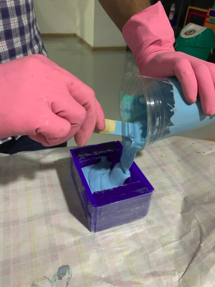
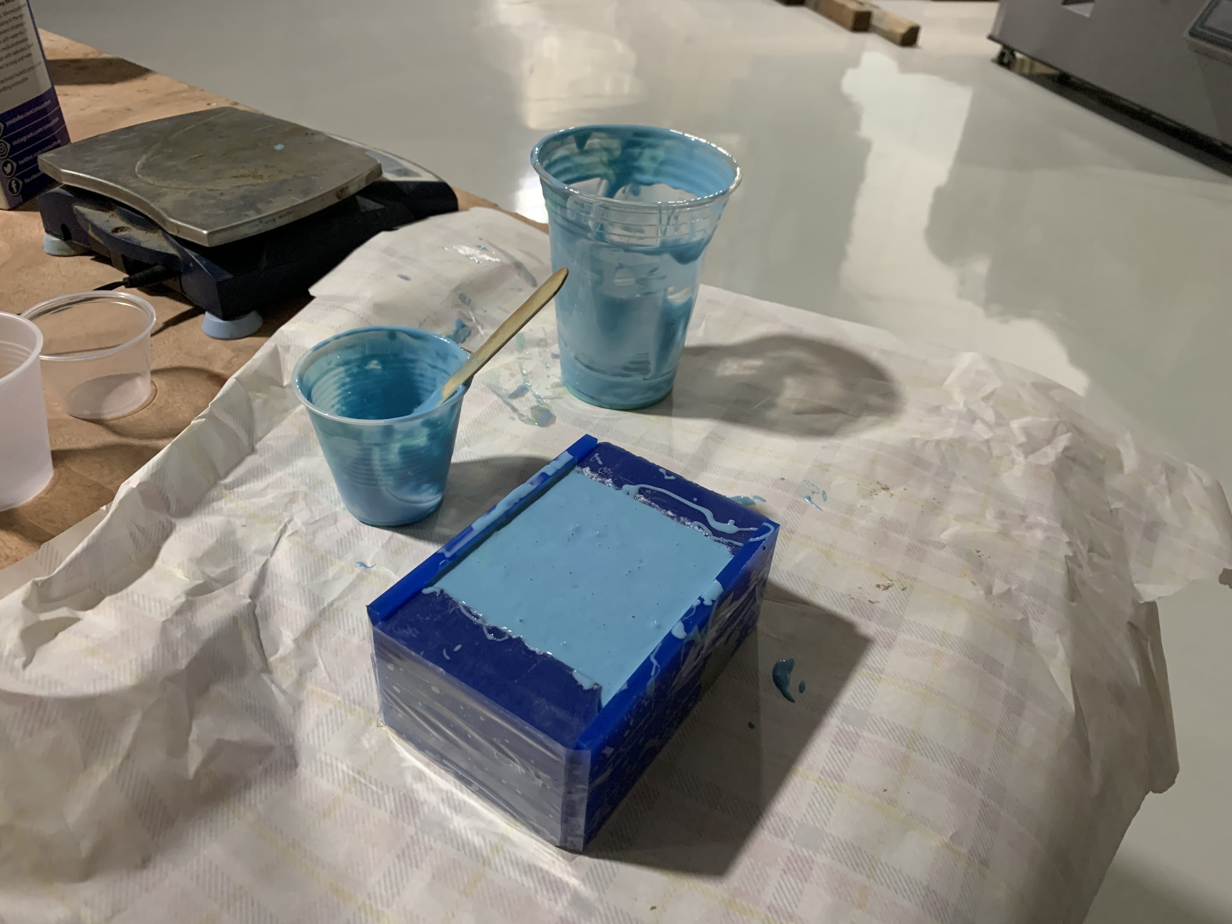
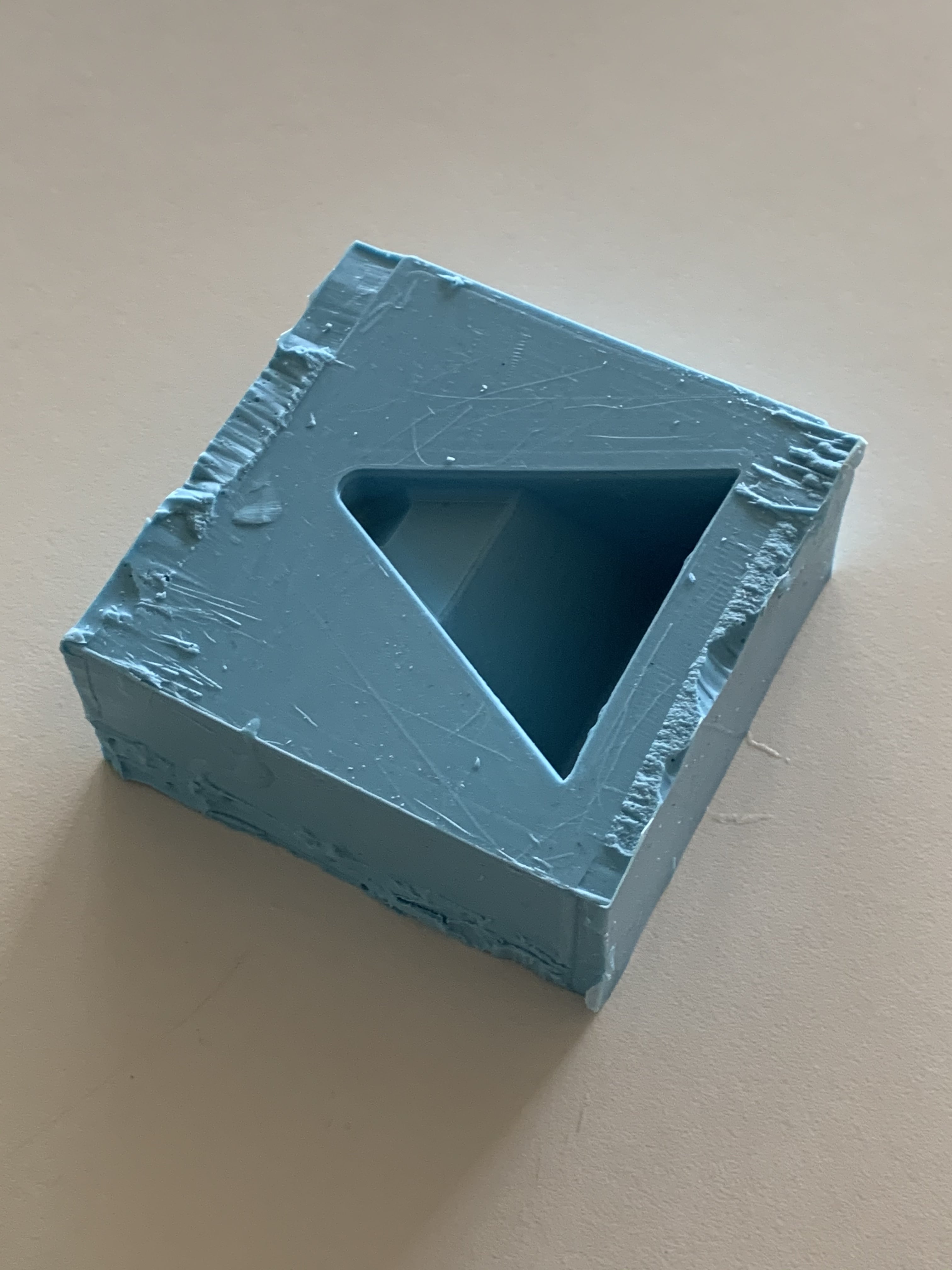
Silicone Moulding
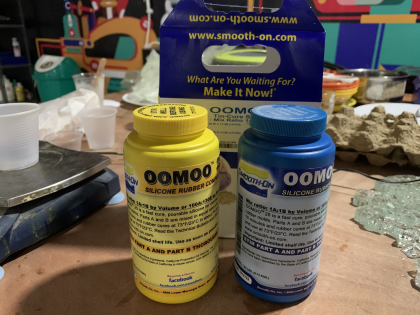
ie. 1g Part A = 1.3g Part B
so, 83g Part A = 109g Part B
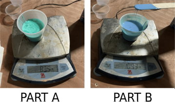
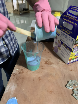
Then I kept the mixture for curing for 75min at room temperature.
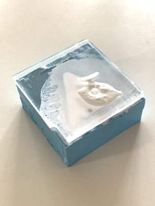
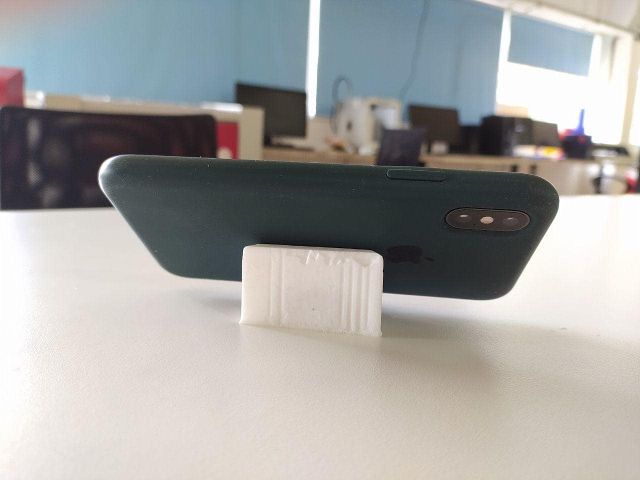
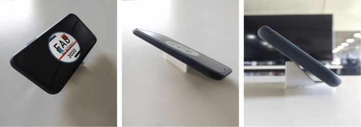
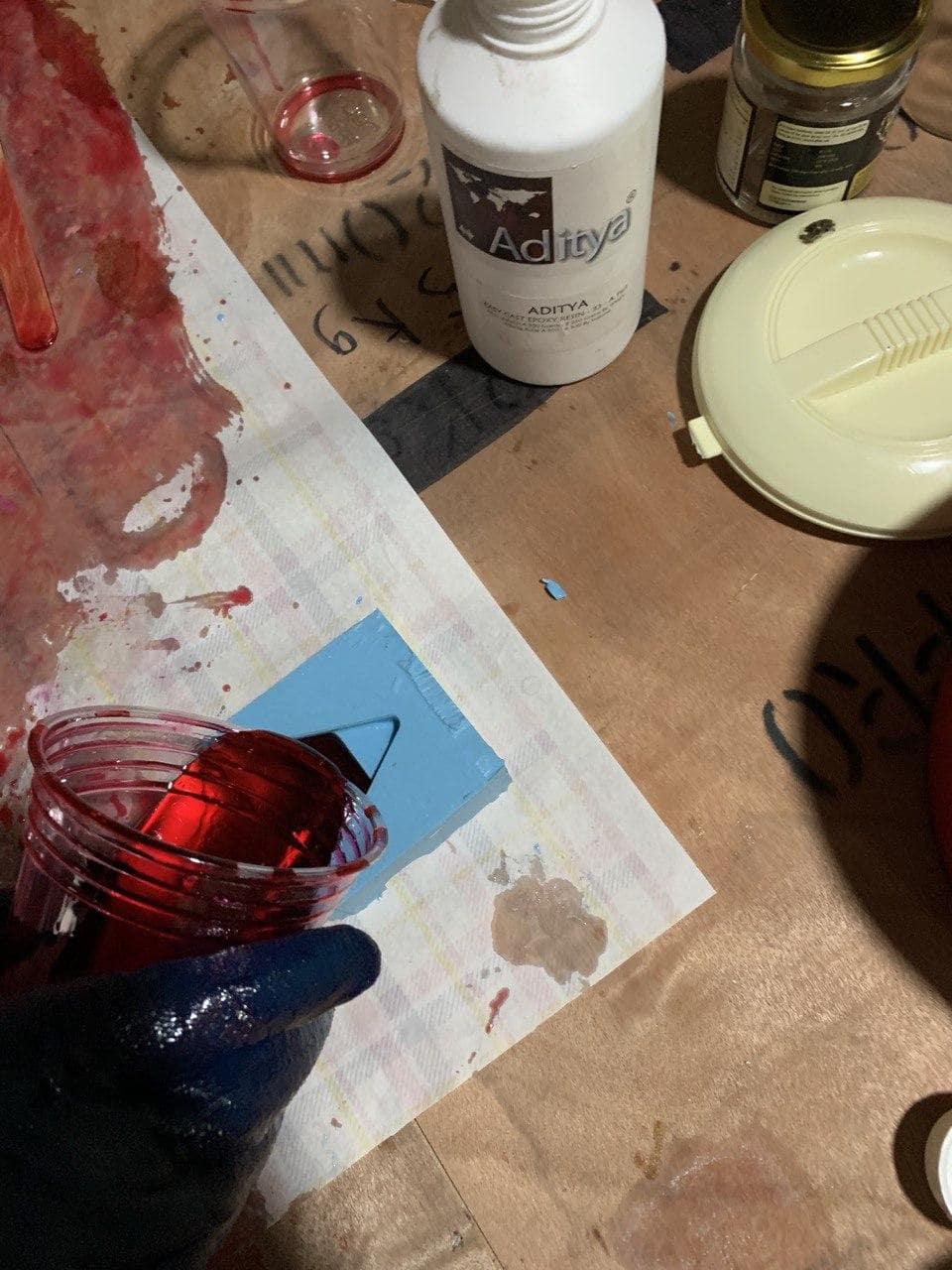
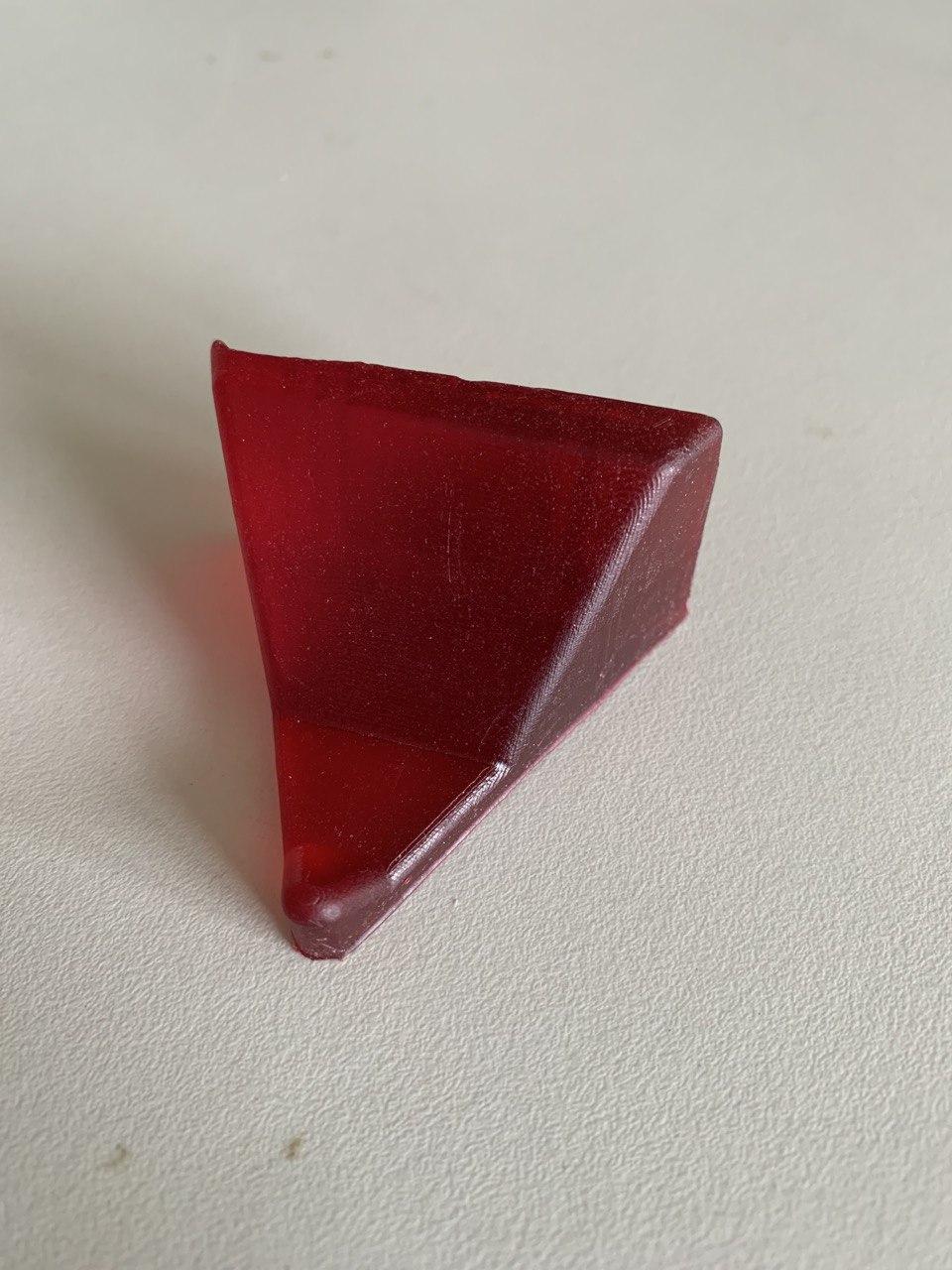
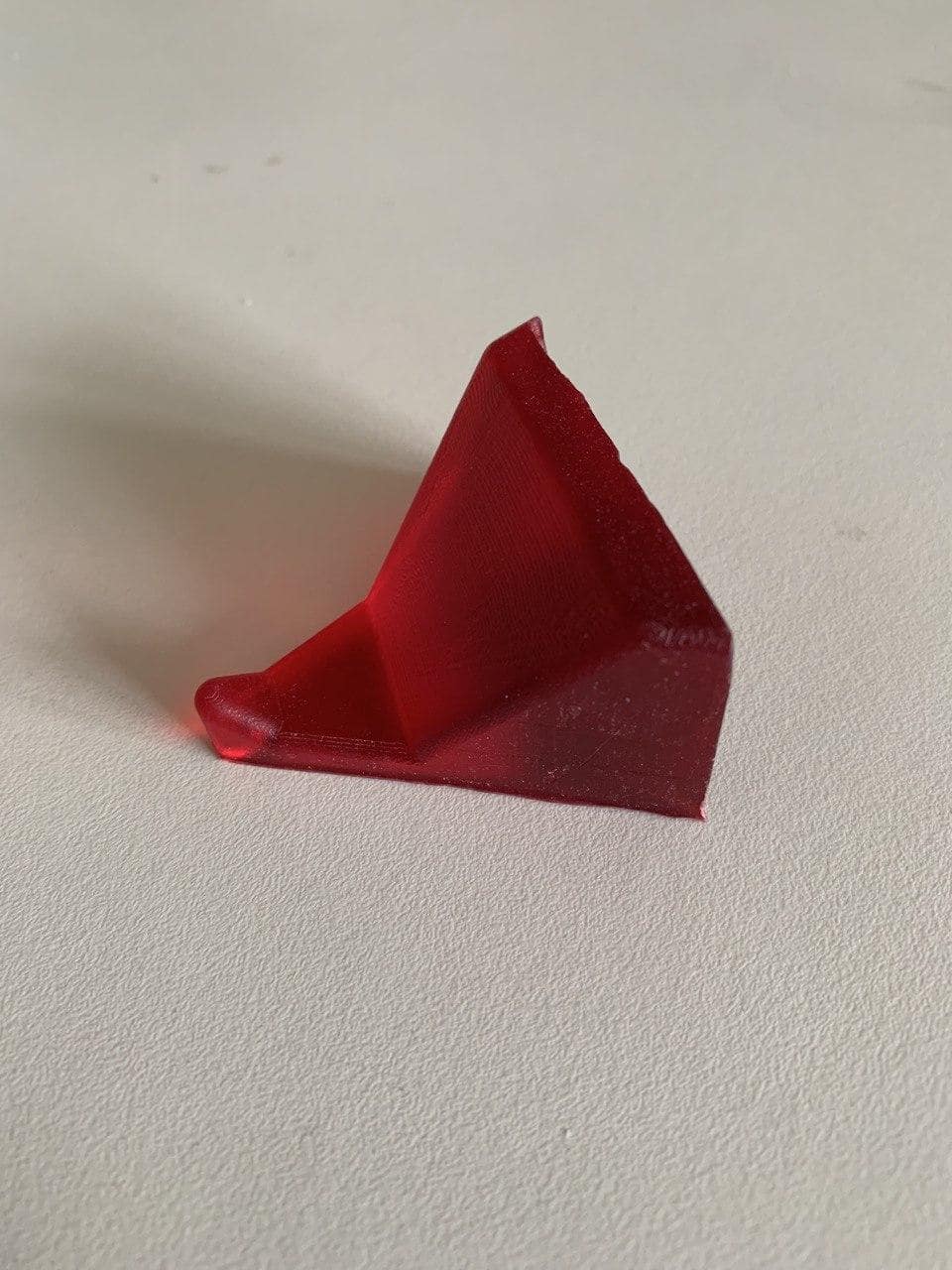
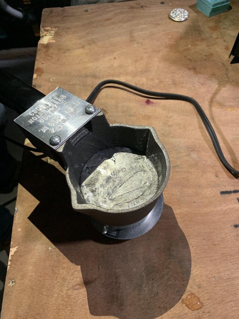
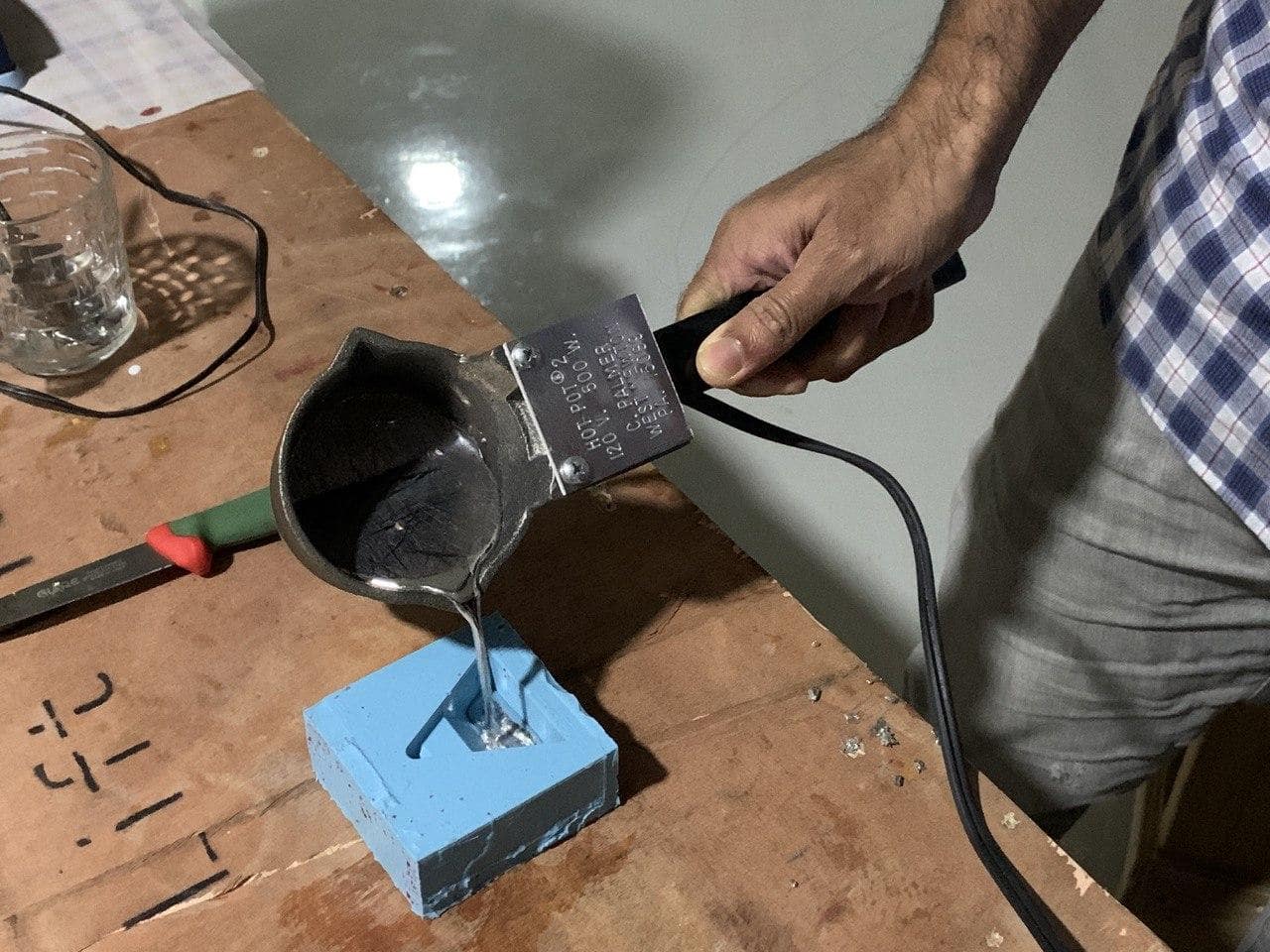
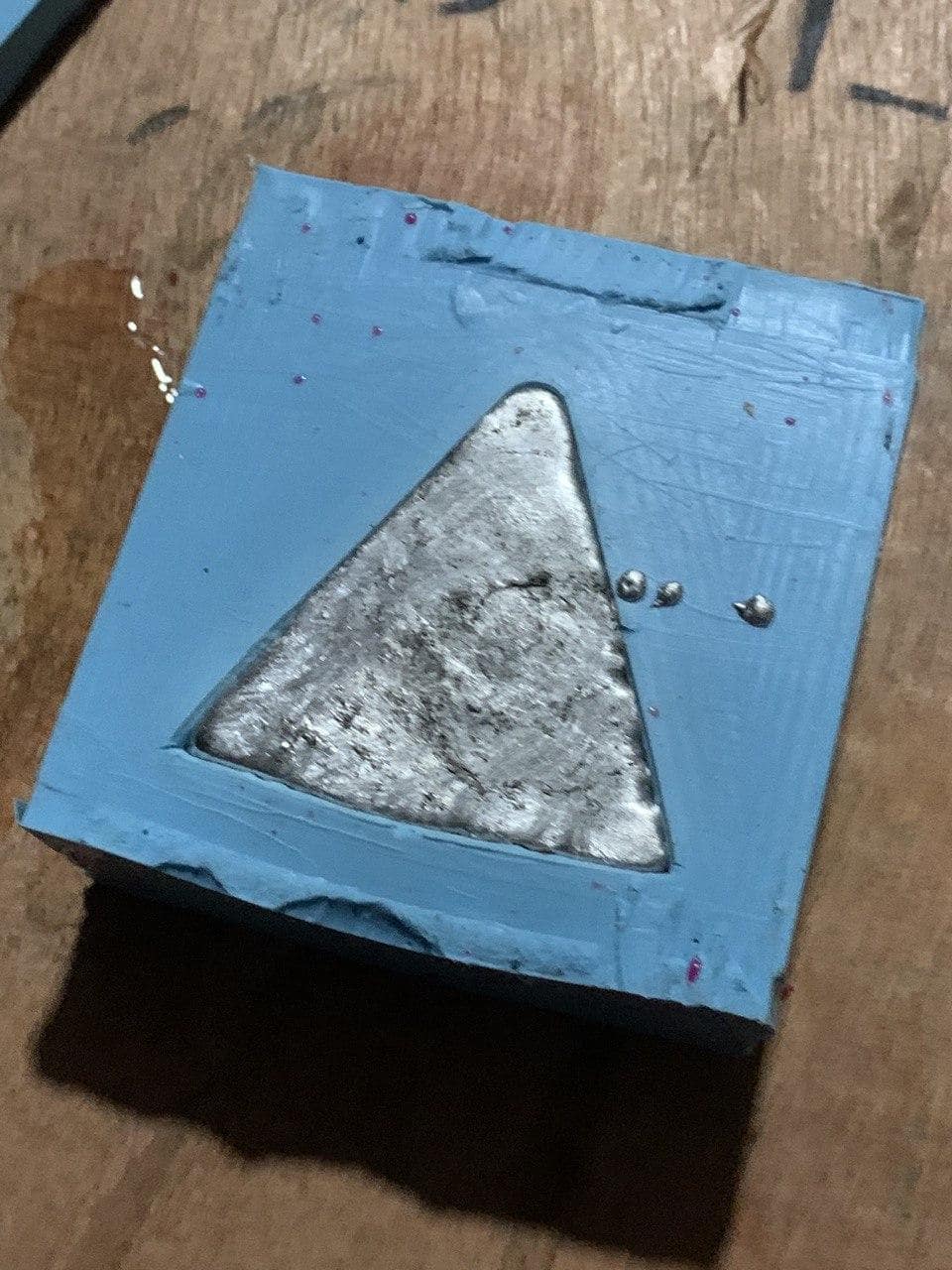
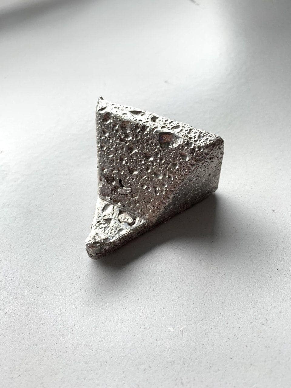
Casting
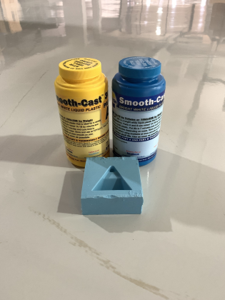
ie. 1g Part A = 0.9g Part B
so, 35g Part A = 31.5g Part B