Week 5
Electronics Production
Objectives
Individual Assignment
Group Assignment
Learning Outcomes
Individual Assignment
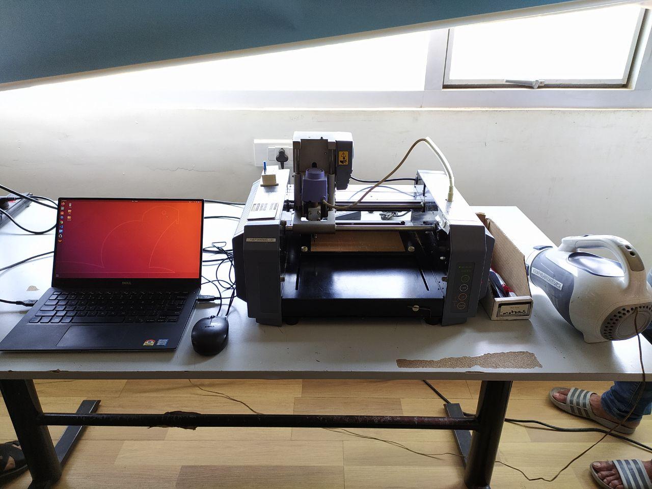
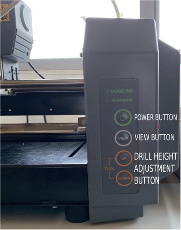
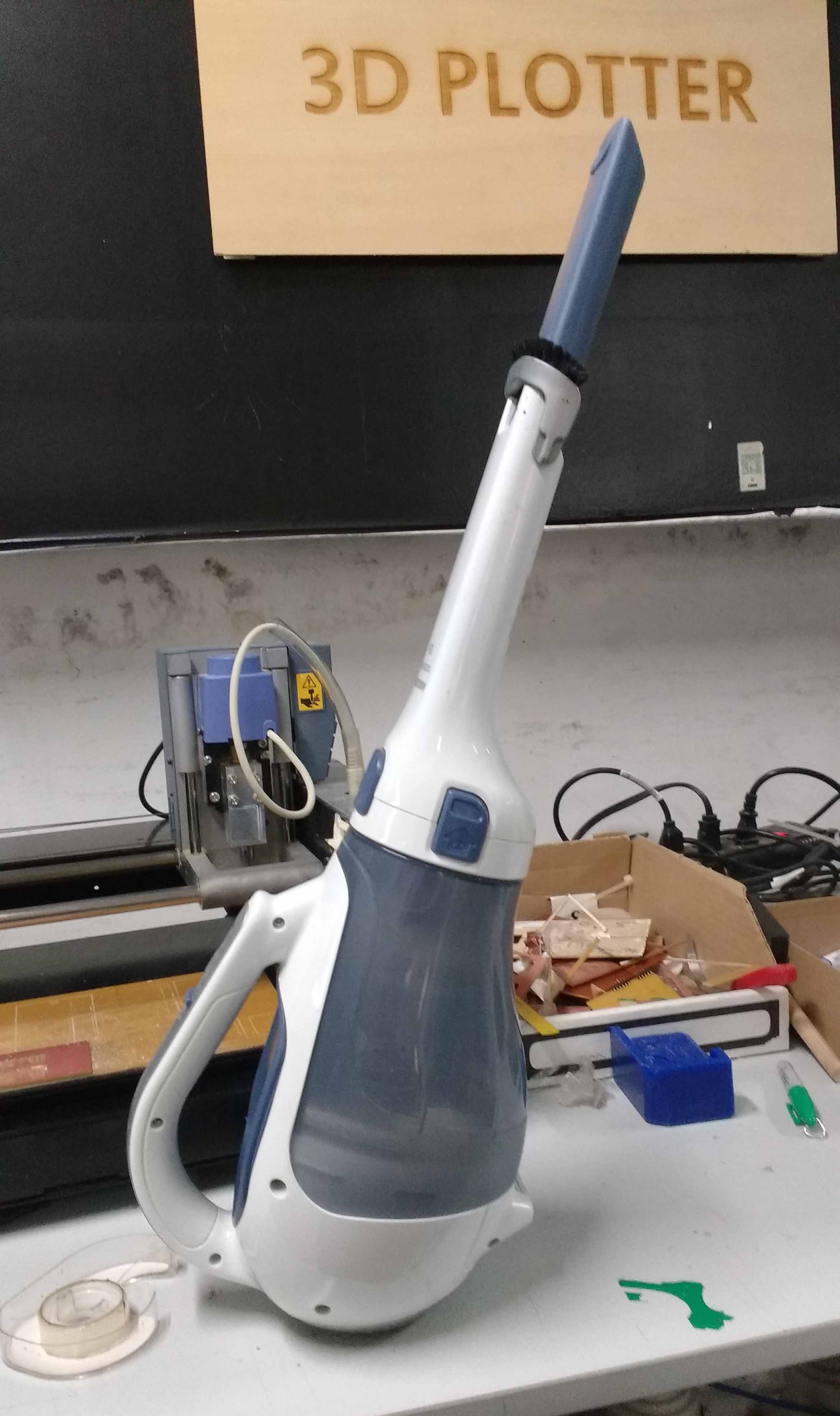
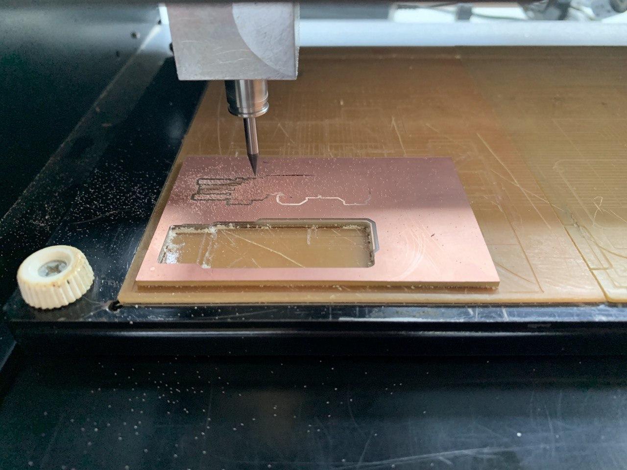
Milling Machine
Milling Tool
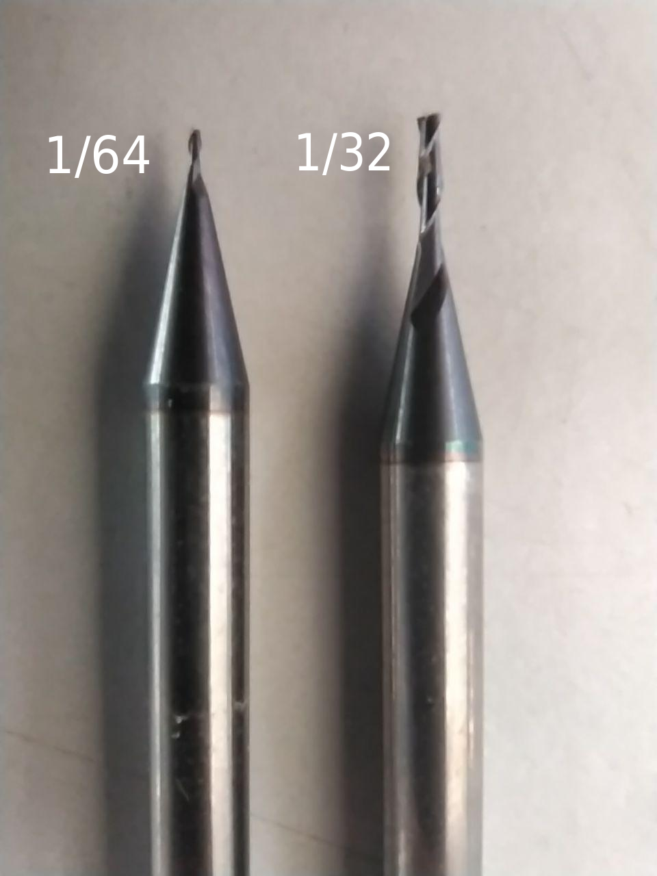
1) 1/64 tip - It is used for milling traces on the PCB, The tip size is 0.00156in or 1/64 of an inch
2) 1/32 tip - It is used for milling profiles and to cut holes, The tip size is 0.003125in or 1/32 of an inch
Both these tools have carbide tips.
Setting the Tool on Modella
- Raise the Z axis to the top
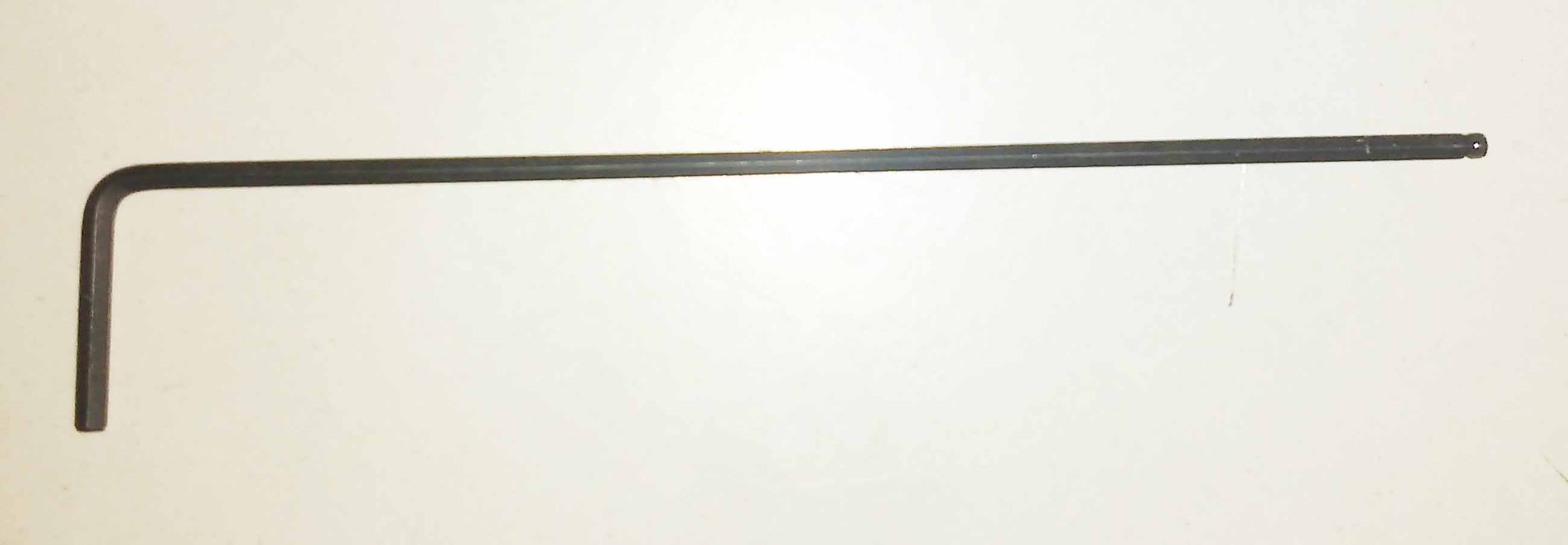
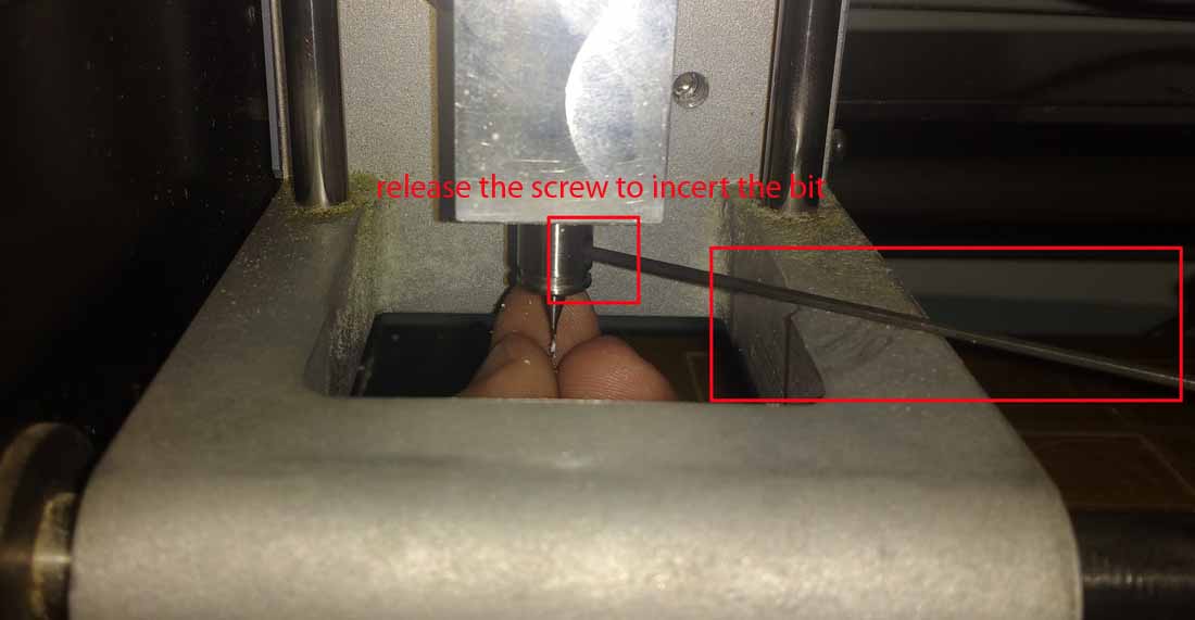
- Release the chuck using the L-key
- Insert the 1/64 inch milling bit a little more in to the chuck
- tight the screw
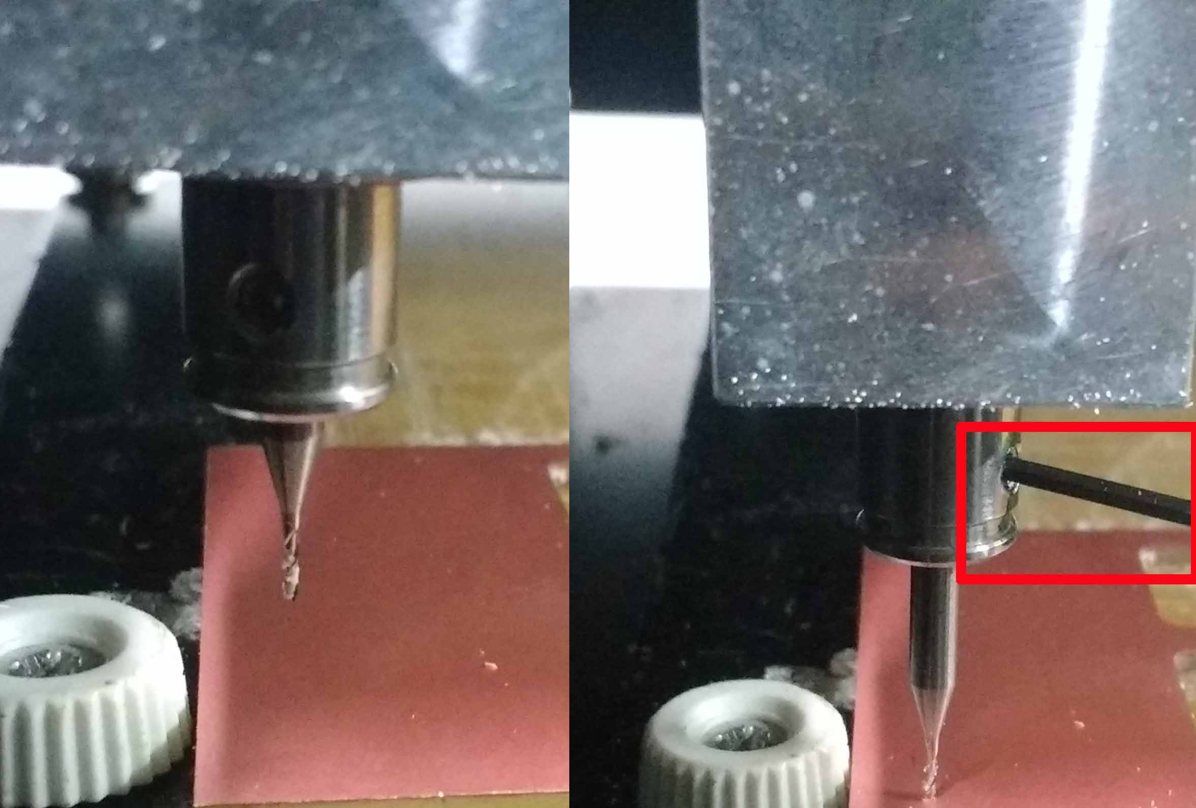
- Down the z axis close as possible to the bed
- Unscrew the chuck and release the bit
- Slightly press the bit close to the bed and tight the chuck screw
- Done
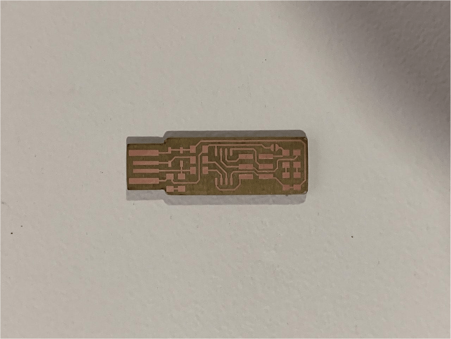
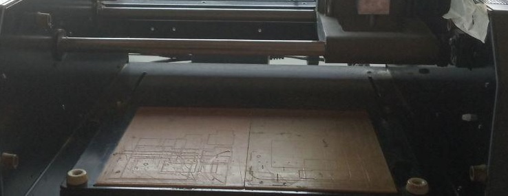
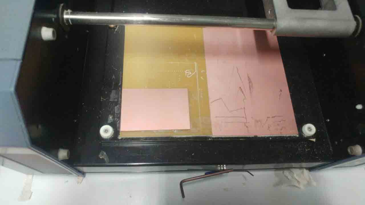
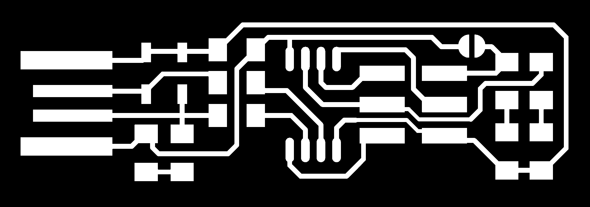
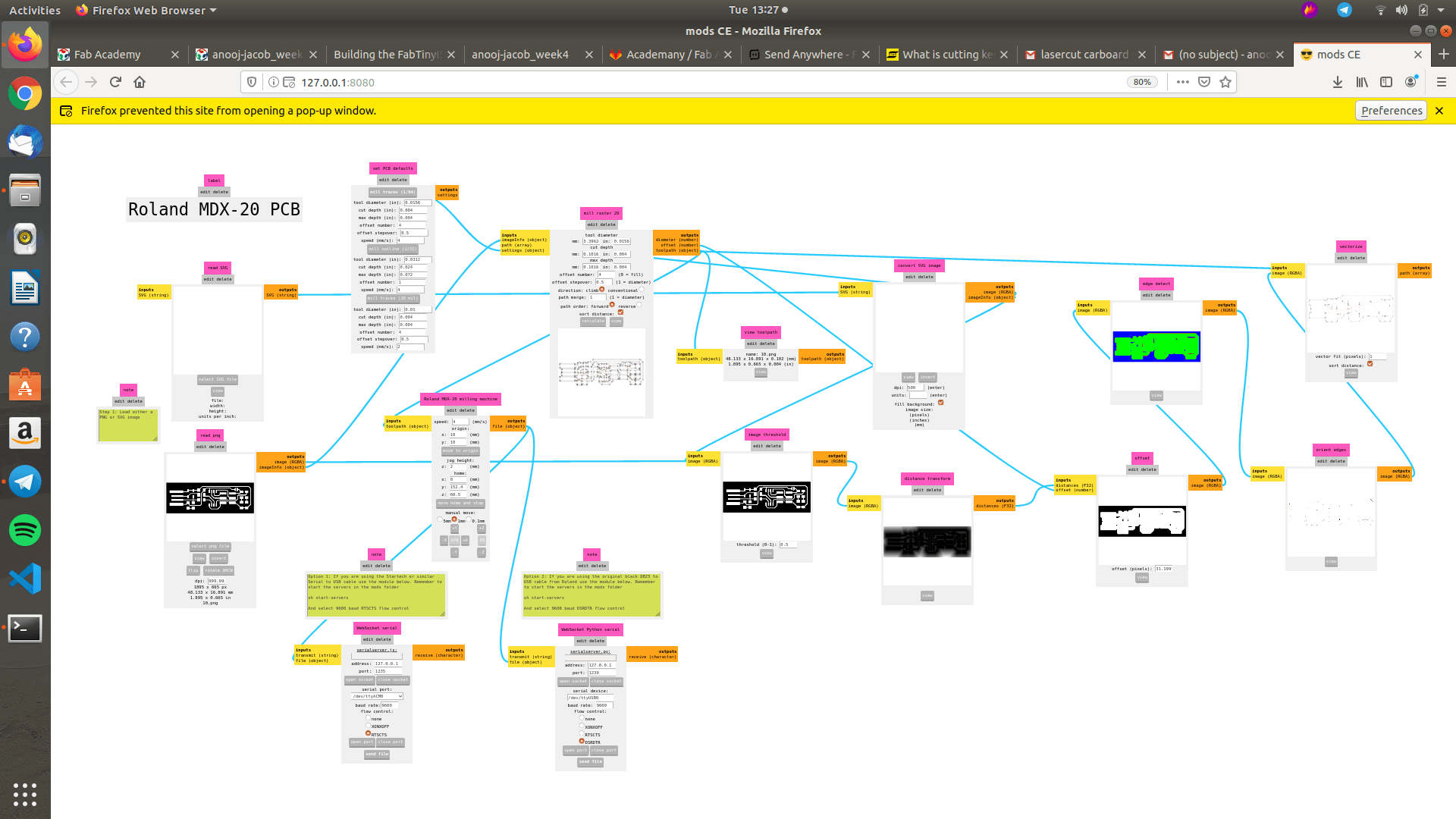
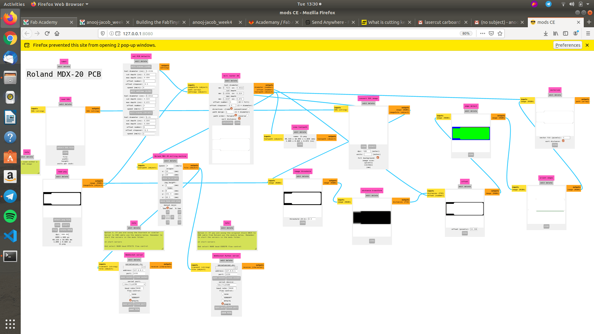
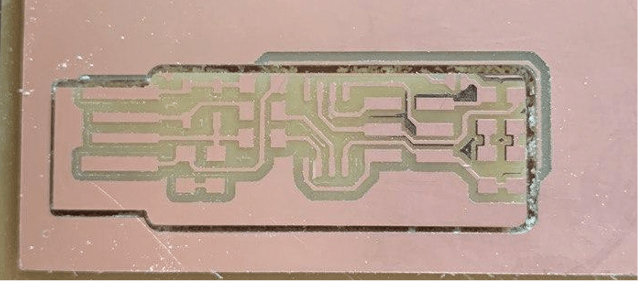
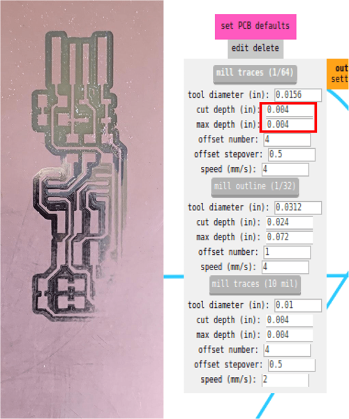
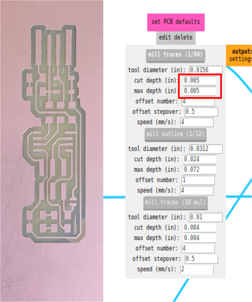
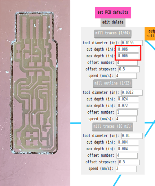
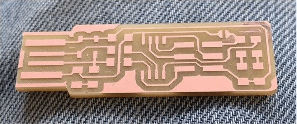
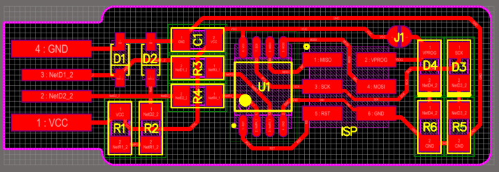
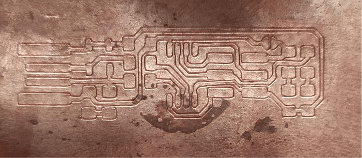
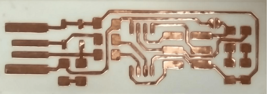
Making the PCB

MISTAKE
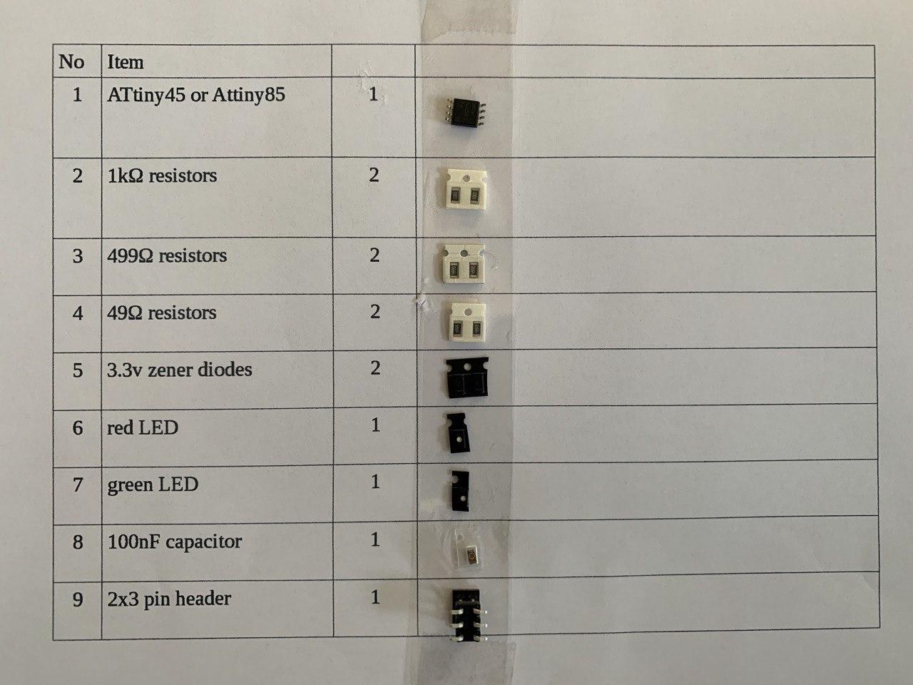
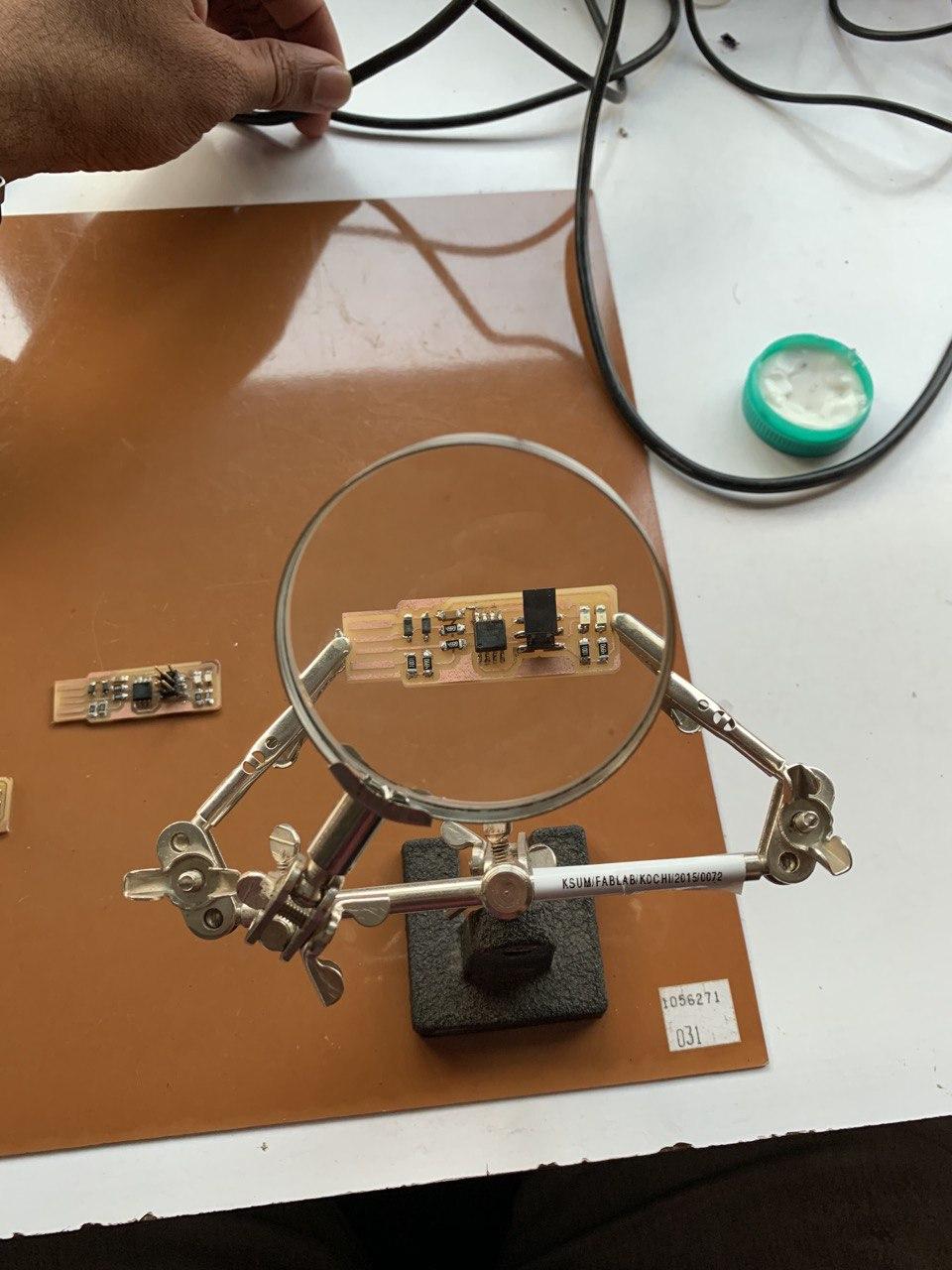
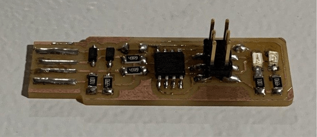
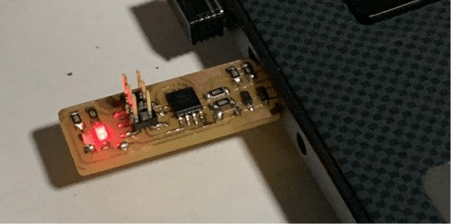
Soldering the Circuit
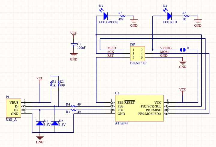
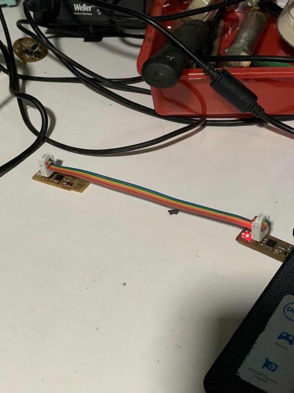
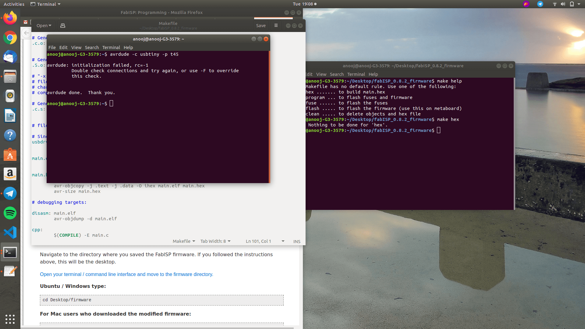
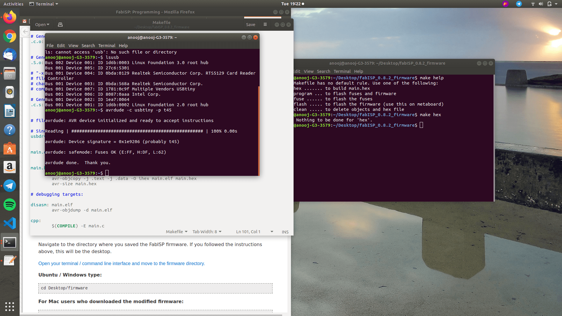
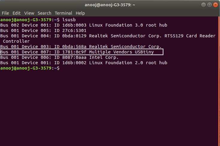
Programming the Micro-Controller
Vinyl cutting of PCB
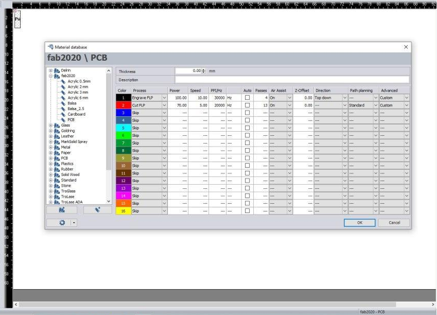
Laser cutting of PCB