
Week 09. Input Devices
This week there are also two types of assignments, one group and one individual. In my case being alone in the Fab Lab, I do both.
- Probe an input device(s)'s analog and digital signals. ✔
- Document your work (in a group or individually). ✔
- Measure something: add a sensor to a microcontroller board that you have designed and read it. ✔
- Linked to the group assignment page. ✔
- Documented what you learned from interfacing an input device(s) to microcontroller and how the physical property relates to the measured results. ✔
- Documented your design and fabrication process or linked to previous examples. ✔
- Explained the programming process/es you used. ✔
- Explained problems and how you fixed them. ✔
- Included original design files and source code. ✔
- Included a ‘hero shot/video’ of your board. ✔
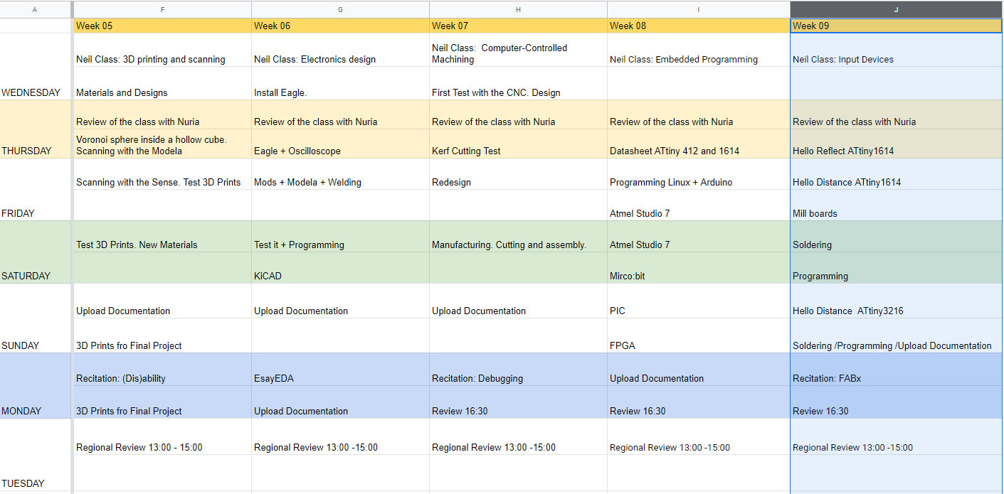
Like every week, my weekly schedule. 😊
This week I am going to try to make two inputs, a Hello Reflect / Light with normal light or infrared and another Hello Distance with the Time of Flight sensor. My idea is to try to test the inputs that I am going to use to see which is the best for my final project. 😅
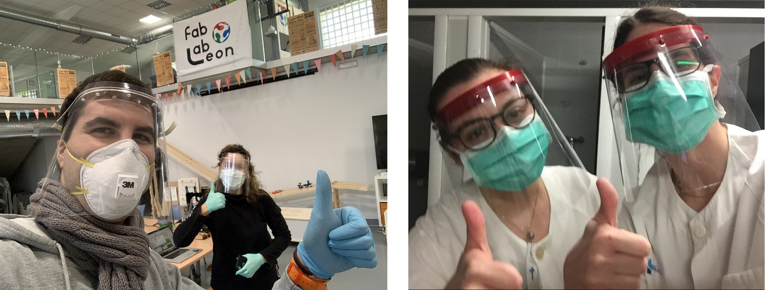
The Fab Lab León is closed to the general public due to the coronavirus 😷, but the c(u)ore is working and helping to create a protective face shield for nurses, doctors ... Nuria, Pablo and I have been printing in 3D and now we are also doing them with laser cutting. The girl on the right is my sister who is a nurse, and very proud of her and that she is wearing the shield that her brother 3D printed. 😘
Group Assignment
The Group Assignment page is at the following link.
If you click on this link, you go to the Group Assignment section that I have done for this week.
Hello Reflect / Light.
Design
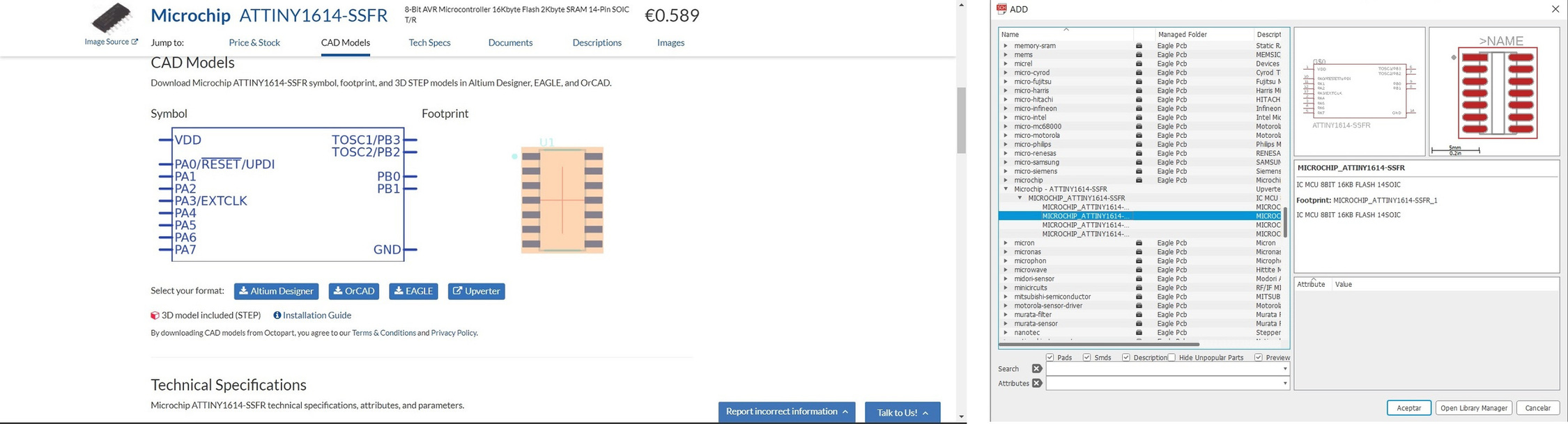
For the Hello Reflect / Light I am going to use the ATtiny 1614. I use Eagle, and as in Week 06 it does not exist in the footprint library of said microcontroller. I was using the ATtiny44 footprint. During the Regional Review, Nuria showed us the Octopart page, where by chance the ATtiny1614 footprint appeared. Thanks Nuria. 😘
Once the footprint and the outline have been downloaded, I add it to the library.
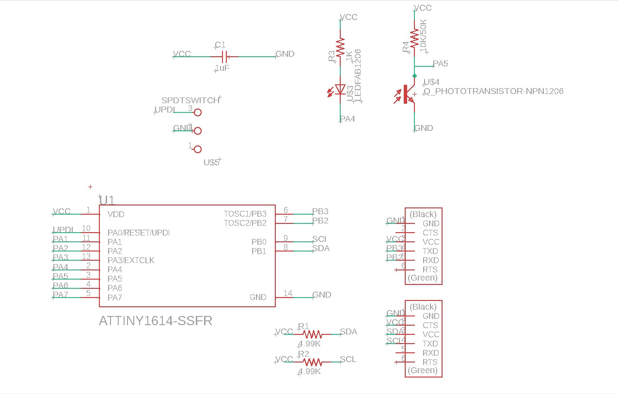
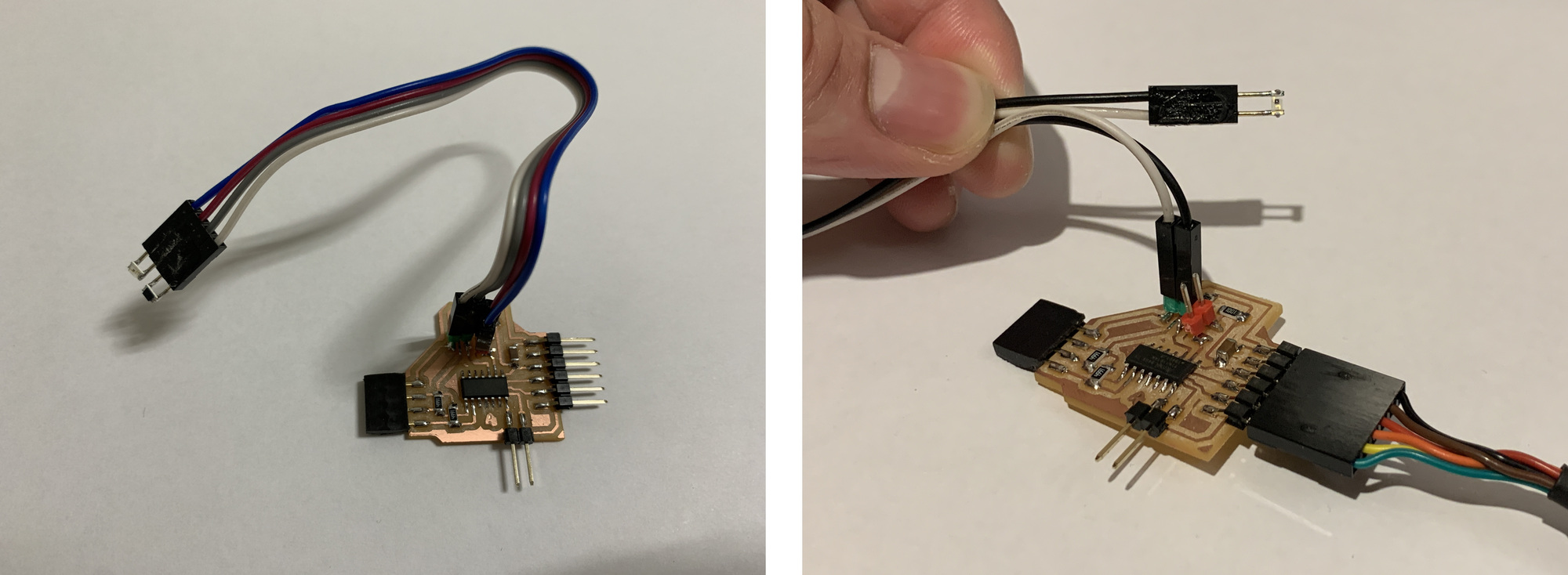
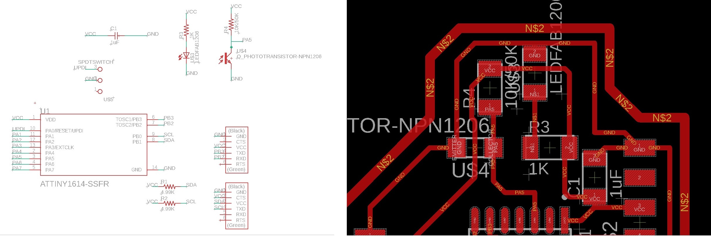
I use Neil's Hello Reflect and the one made by Japi Contonente during his Fab Academy 2013. For my project as phototransistors and LEDs are going to go under the track, I'm going to use cables with connectors to test if it works. These connectors also help me to use a visible or IR phototransistor. I have included a connector for I2C communications. This is the result of the schematic using the ATtiny1614.
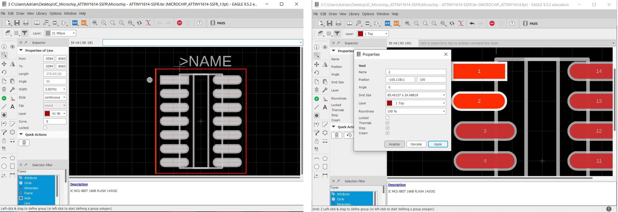
When I started drawing the board, I ran into a little problem. The ATtiny1614 footprint has a layer with an outer contour that even if you turn it off you cannot trace the lines. 😰
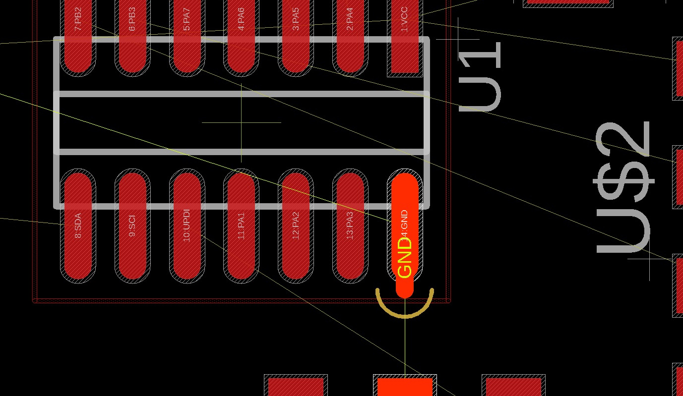
But within the component properties menu there is a tool Footprint Properties that allows us to edit the component. So I delete the outer line and take the opportunity to modify the paths, I make them a little smaller so that I can fit 3 lines between the pins of the ATtiny.
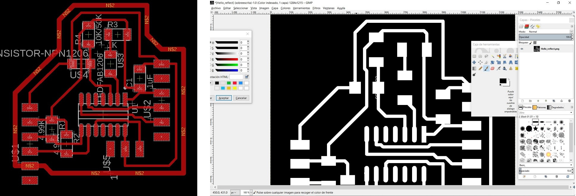
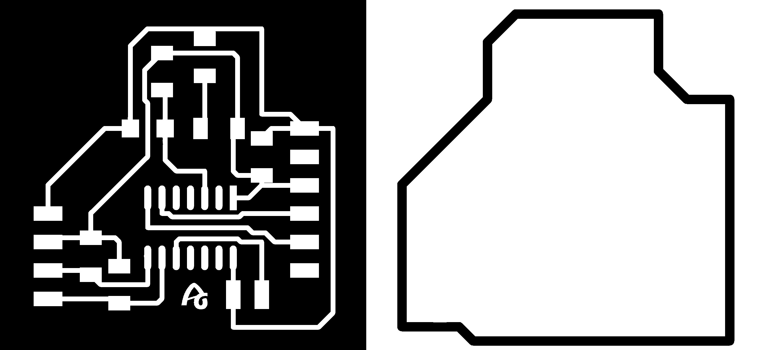
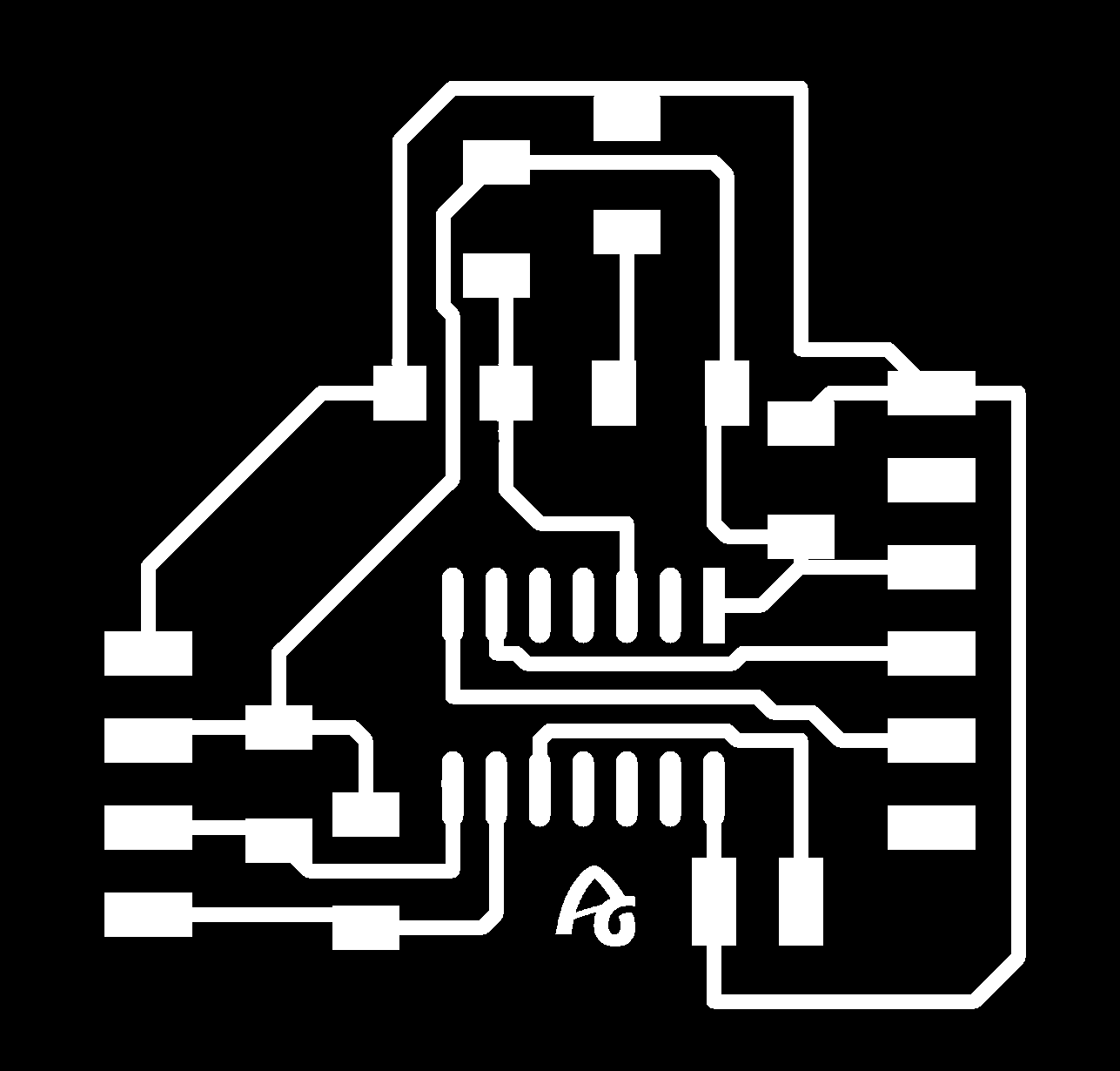
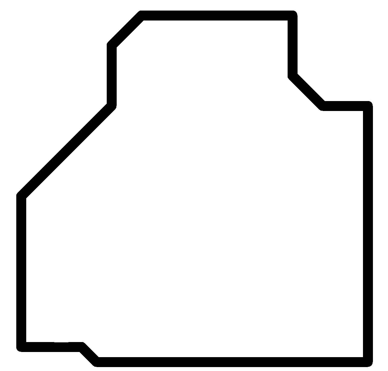
This is the end result of the board. After exporting it as a monochrome image, I use GIMP to create the outer border and erase the paths I don't need from the connectors.
Making
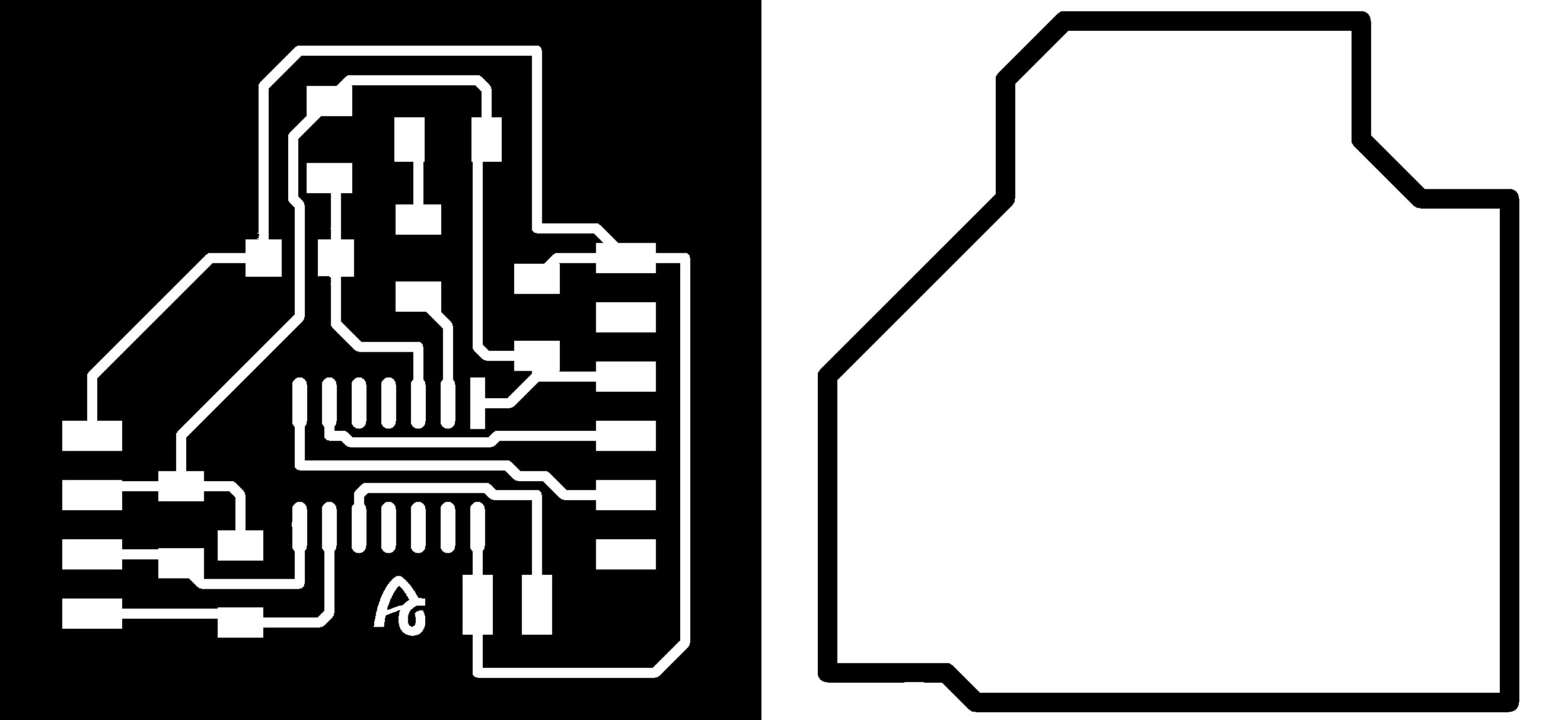
And these are the two images ready to use in the Modela.
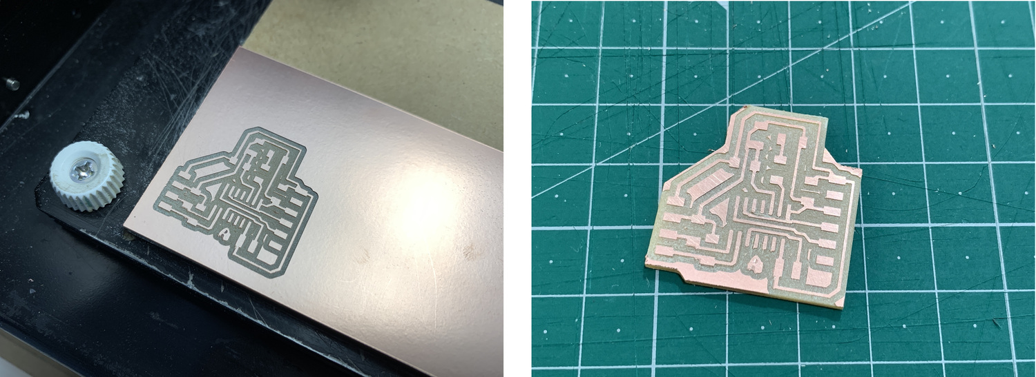
After milling the board using Mods CE, this is the end result.
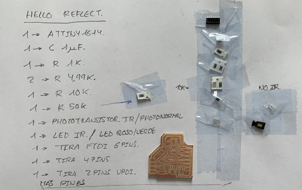
This is the list of components, I take another 50K resistor to test the sensitivity of the phototransistor. In principle I will use the 10K. Also as I have mentioned above, I am going to use the two types of phototransistor so I take the Visible and the IR with the corresponding LEDs (visible and IR).
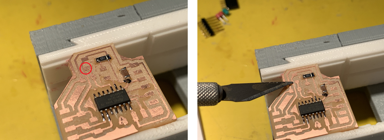
During the soldering process, I realize that there are two tracks attached, the mill did not remove the copper that was not necessary. So with a knife I remove the small piece.
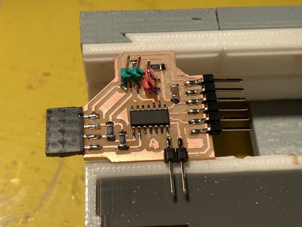
Once the problem is solved, this is the result with the board finished, in the absence of soldering the cables with the phototransistors.
Following the datasheet of the phototransistors and the IR LED, this is their connection. These are the Datasheet links. Phototransistor IR PT15-21B Infrared LED IR15-21C Phototransistor PT15-21C
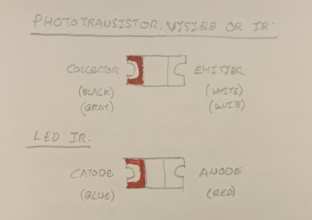
This is how it would look, the Hello Reflect on the left and the Hello Light on the right.
Here is the video of the soldering process.
Programming: Arduino + Linux.
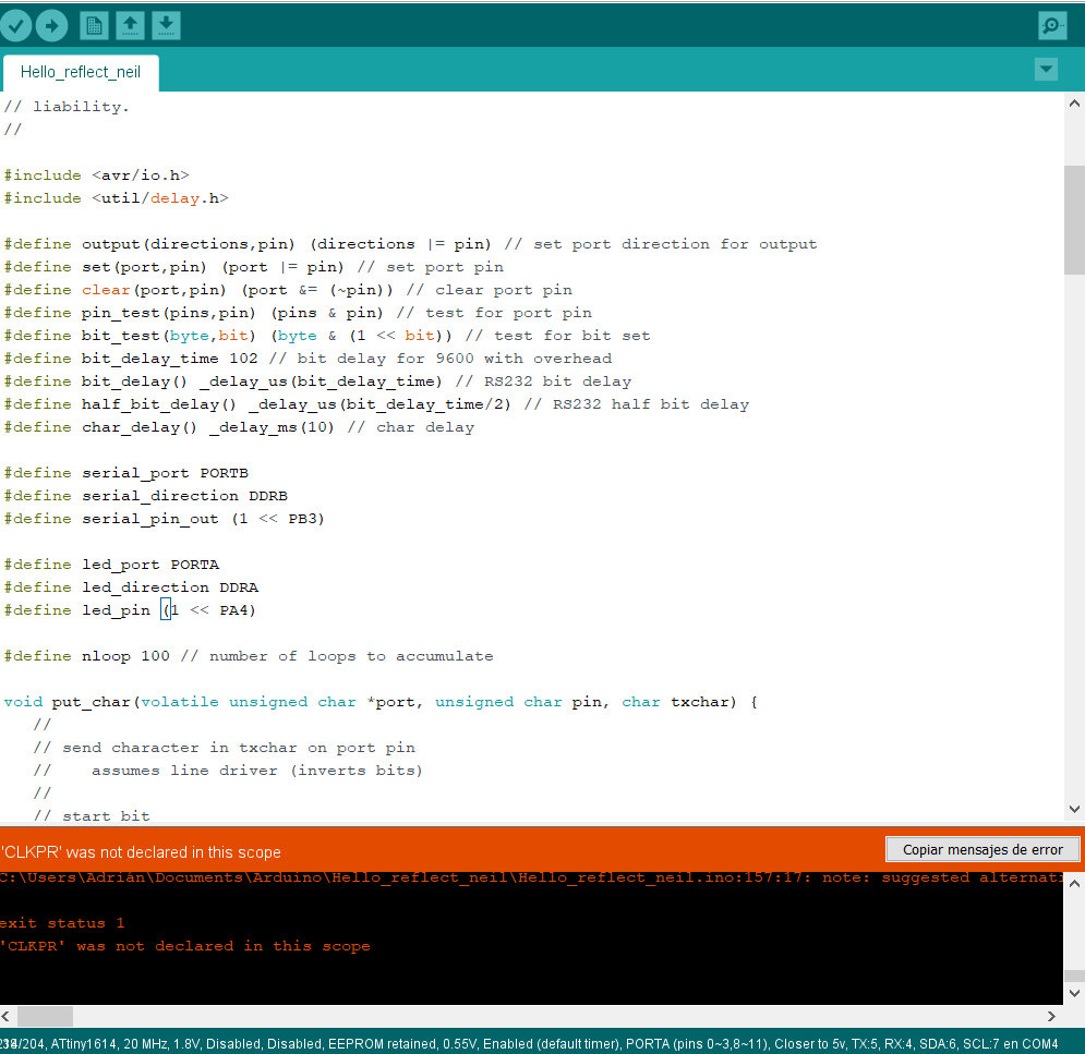
The first thing I do is download the Neil program from Hello Reflect. It is in C and for the ATtiny45. I try to modify it for the ATtiny1614 but it gives me errors and I don't understand them.
I speak to my instructor Pablo, and he tells me why I don't do spiral development. Start with the Visible phototransistor and then go to the IR light phototransistor. That look for easy programs in Arduino, from other years. Thank you, Master Pablo. 🤗
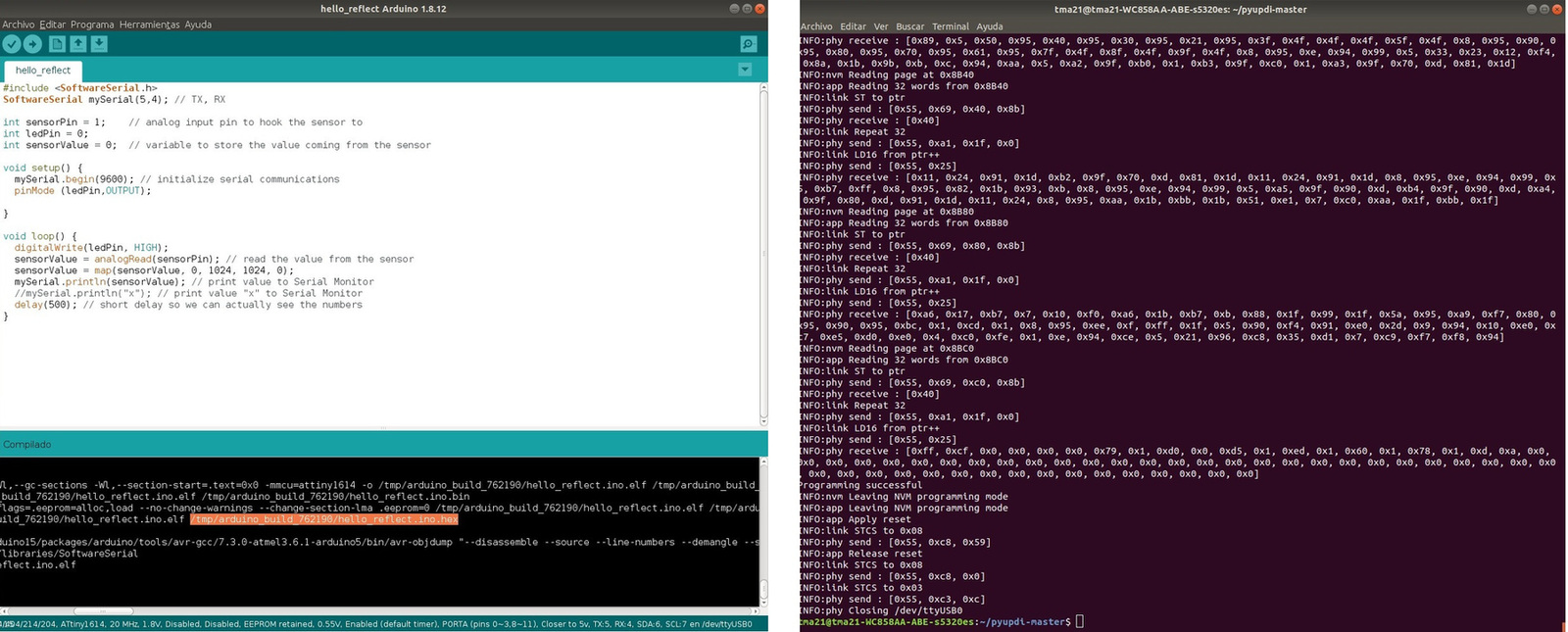
So I replaced the IR phototransistor with the visible one. I am going to use the Elena Cardiel program that I used last year at the Fab Academy. I compile it, load it and it seems to work.
To use the Pyserial, I follow the tutorial that Pablo taught me that they used in the Bootcamp in India that Santi from Fab Lab BCN created.
Listen the serial port python -m serial.tools.miniterm /dev/ttyUSB0 9600
But it does not work. 😪
I talk to Pablo again, and comparing Neil's code from the Hello Echo from last week and mine, the Serial Communication Speed does not match. I have 9600 and Neil has 115200. Santi also has the same in the tutorial, 115200. It happens to me for not reading. 😖 Thank you very much Pablo. 😇
So I modify the code so that it has the speed of 115200. I reload it with the UPDI and read the PySerial.
Listen the serial port python -m serial.tools.miniterm /dev/ttyUSB0 115200
And works. Here the data capture and the video.
Here is the Arduino code.
//Original code: Elena Cardiel. Fab Academy 2019.
//
//Modified by Adrián Torres. Fab Academy 2020.
//
//ATtiny1614

int sensorPin = 1;    // analog input pin to hook the sensor to
int sensorValue = 0;  // variable to store the value coming from the sensor

void setup() {
  Serial.begin(115200); // initialize serial communications
}

void loop() {
  sensorValue = analogRead(sensorPin); // read the value from the sensor
  sensorValue = map(sensorValue, 0, 1024, 1024, 0);
  Serial.println(sensorValue); // print value to Serial Monitor
  //mySerial.println("x"); // print value "x" to Serial Monitor
  delay(500); // short delay so we can actually see the numbers
}
At the moment the Hello Reflect I'm going to wait, I'm going to test how the Hello Light works with the Visible phototransistor when the train passes. You can see the proof in Project Management
Group Assignment
The Group Assignment page is at the following link.
Measurement with the oscilloscope
Measured with the oscilloscope of an analog signal, in this case the output of the Phototransistor. It is observed how the signal varies when I approach and move away the light.
03/31/2020: Hello Reflect update
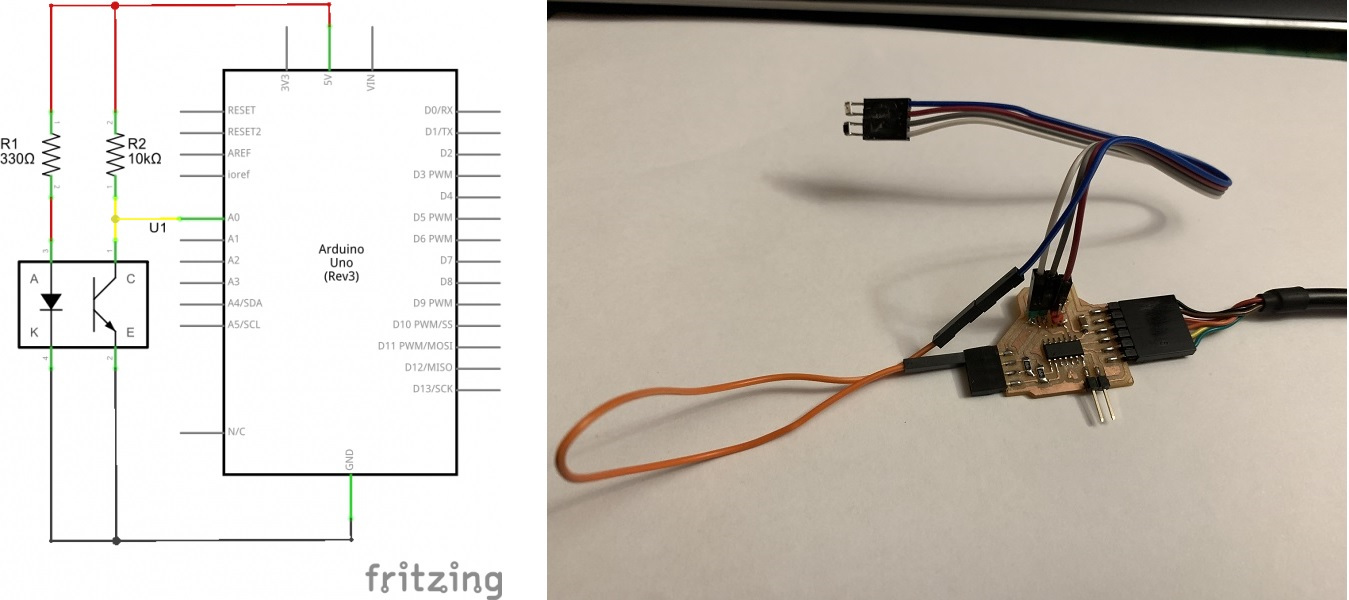
I have continued looking for different examples that use an IR phototransistor, and I have found this Sparkfun page that explains the operation of the QRD1114 Optical Detector Hookup that is based on an IR phototransistor and an IR LED.
Looking at the connection of the QRD114 scheme, the IR LED is not connected to any pin of the Arduino, it is connected to GND. So on my board I'm going to do a test, connecting the cathode of the IR LED to GND. The orange wire is connected to the GND of the I2C connection.
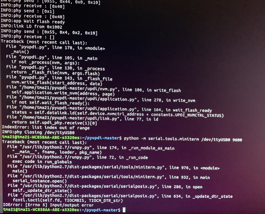
I compile the sample program on the web on Arduino and load it by UPDI with Linux and Pyserial.
Using the PyUPDI and the FT230XS programmer and the converter for UPDI I load the .hex program.
Program the board using python -> run sudo python3 pyupdi.py -d tiny1614 -c /dev/ttyUSB0 -b 19200 -f Hello_Reflect_IR.ino.hex -v
After, listen the serial port python -m serial.tools.miniterm /dev/ttyUSB0 115200
Measurement data is best viewed on video, displays data between 0 and 4.
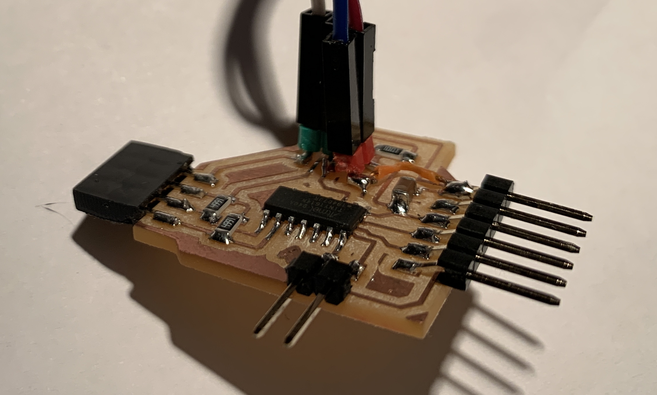
How it works I am going to make a Frankestein, I am going to cut the track that goes to ATtiny1614 and solder it to GND with a small cable. Here is the result.
I modify the schematic and the board in Eagle. I extract the PNG and edit it with GIMP to be able to redo the board again.
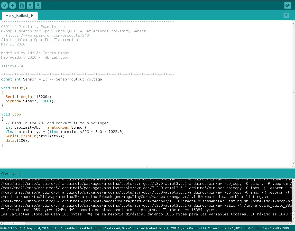
Here is the Arduino code.
/******************************************************************************
QRD1114_Proximity_Example.ino
Example sketch for SparkFun's QRD1114 Reflectance Proximity Sensor
  (https://www.sparkfun.com/products/246)
Jim Lindblom @ SparkFun Electronics
May 2, 2016

Modified by Adrián Torres Omaña
Fab Academy 2020 - Fab Lab León

ATtiny1614

******************************************************************************/
const int Sensor = 1; // Sensor output voltage

void setup()
{
  Serial.begin(115200);
  pinMode(Sensor, INPUT);
}

void loop()
{
  // Read in the ADC and convert it to a voltage:
  int proximityADC = analogRead(Sensor);
  float proximityV = (float)proximityADC * 5.0 / 1023.0;
  Serial.println(proximityV);
  delay(100);
}
Here is the files to download.
- ATtiny1614 Library
- Hello Reflect Traces
- Hello Reflect Interior
- Hello Reflect Schematic and Board
- Arduino program Hello Phototransistor
- Arduino program Hello Reflect IR
Hello Distance. Time of Fligth. VL53L0X
Design
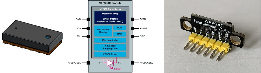
I am going to use a module that integrates the VL53L0X sensor. Last year Alejandro Ulecia used it in his final project and it is very interesting because several sensors can communicate through I2C. The module is sold by Adafruit, although in my case I bought it from Amazon.
I am going to use the ATtiny1614 to communicate with the sensor. In this case of the pinout that the sensor brings, I will only use the VCC, GND, SDA and SCL pins. This information is obtained from the Luis Llamas website.
Using Eagle I design the schematic and the board. I really only use the following pins of the ATtiny1614: VCC, GND, TX, RX, UPDI, SCL and SDA.
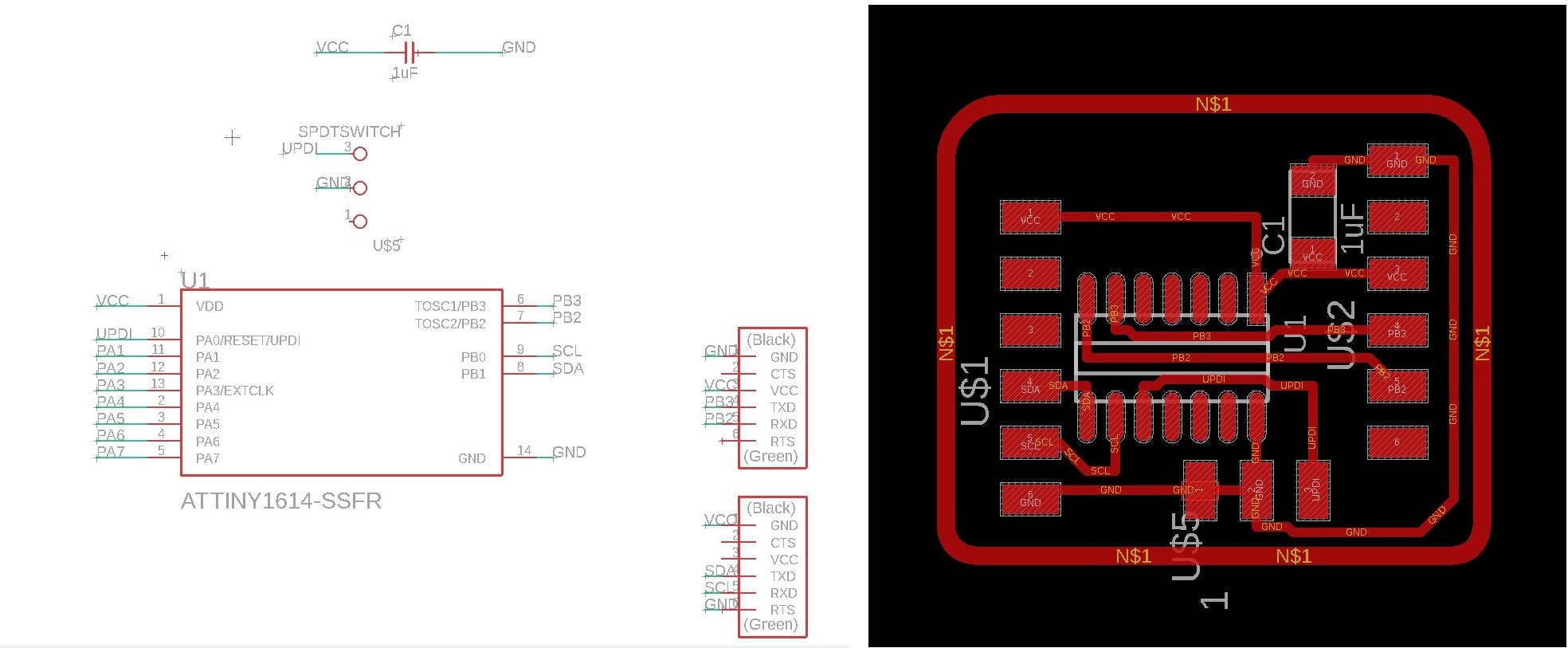
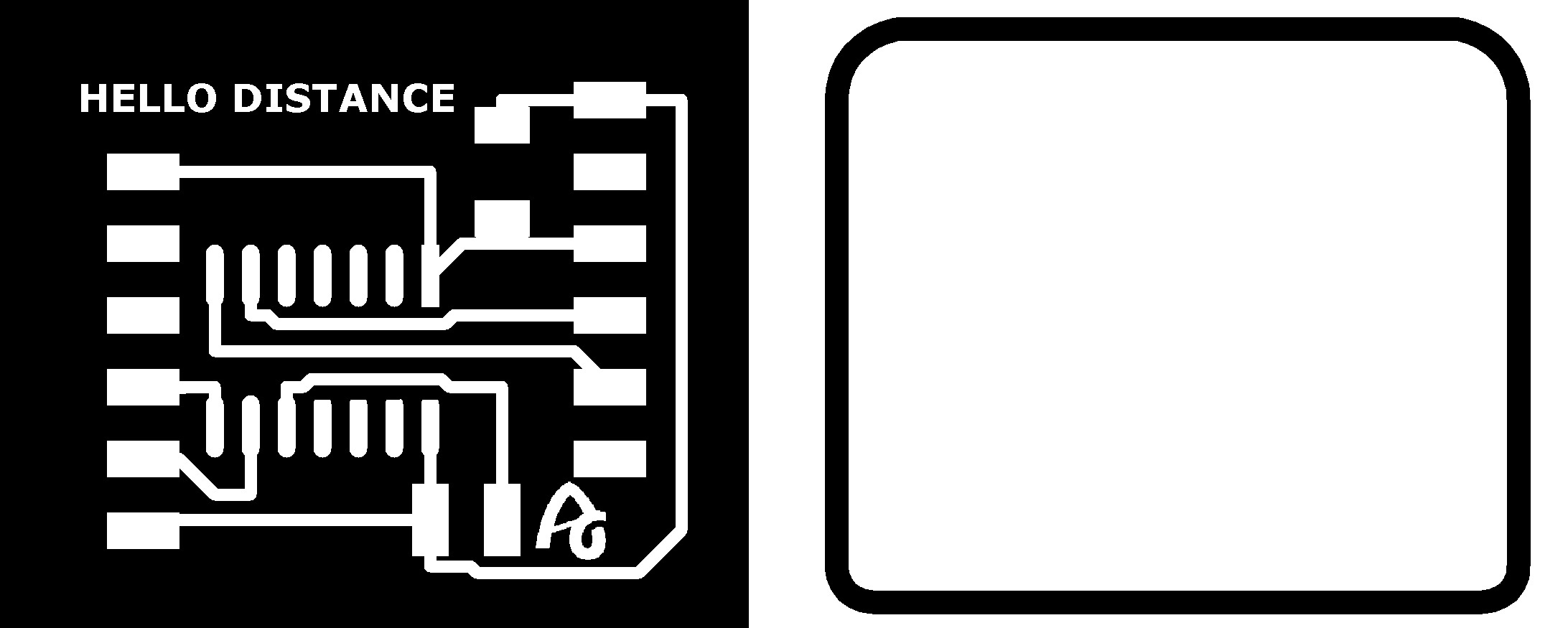
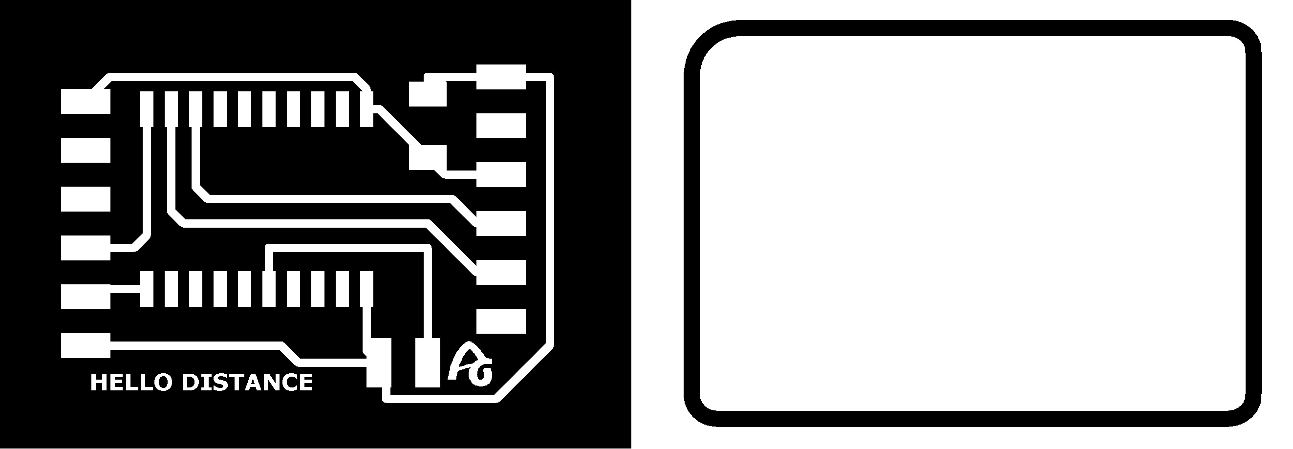
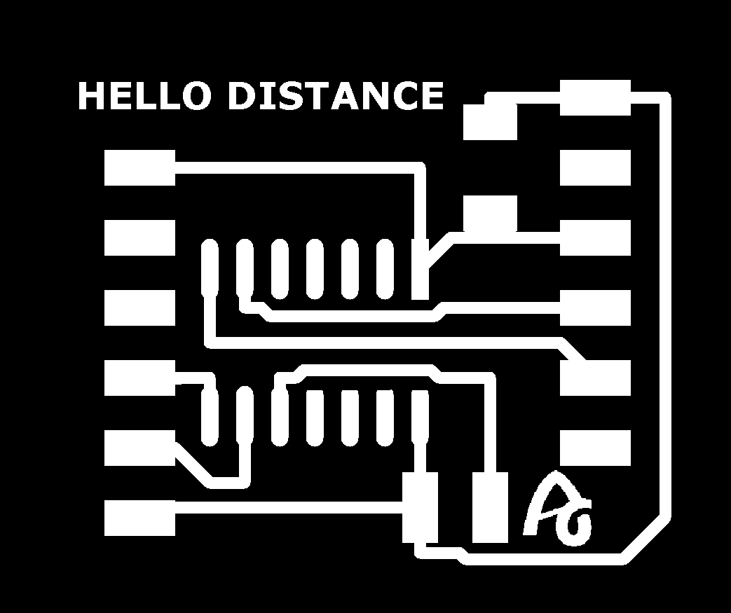
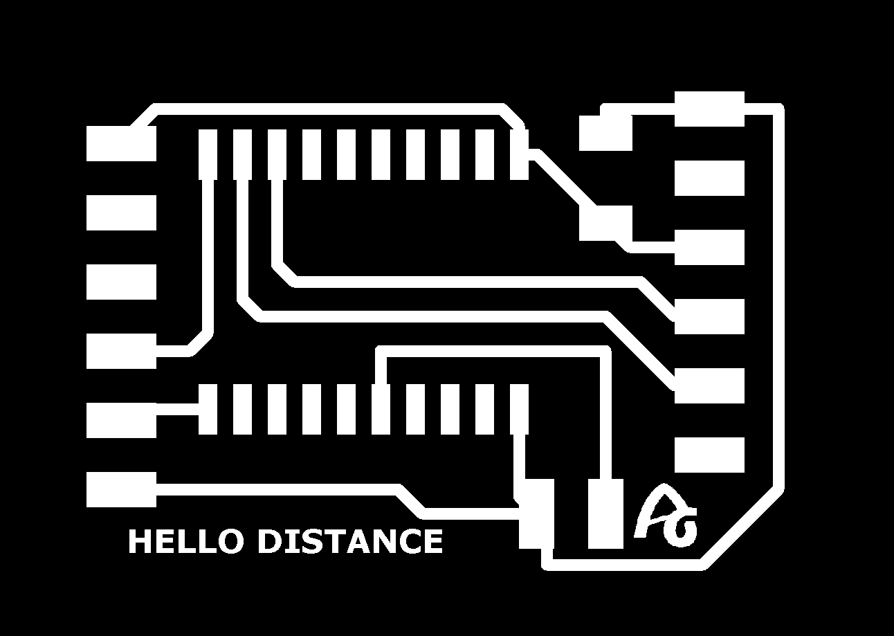
Using GIMP I eliminate the paths that I don't need and I make the outer cut layer.
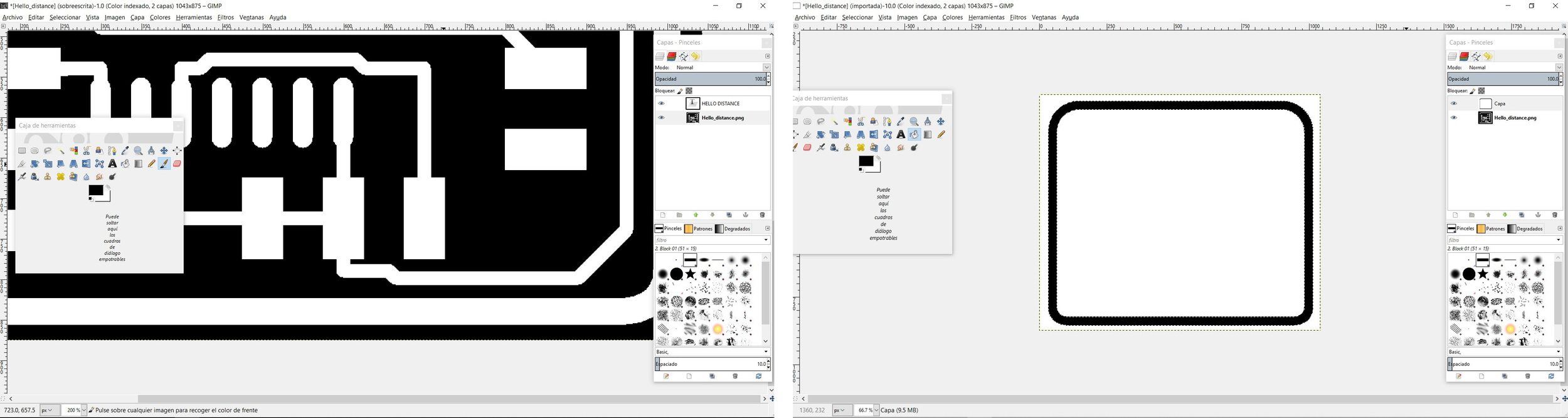
Before sending the work to the Modela, I always like to check with Mods if it is going to mill all the tracks or if it is going to join. In this case the lower pins of the ATtiny1614 would all be joined. With the GIMP, I modify with black color and make the paths smaller.
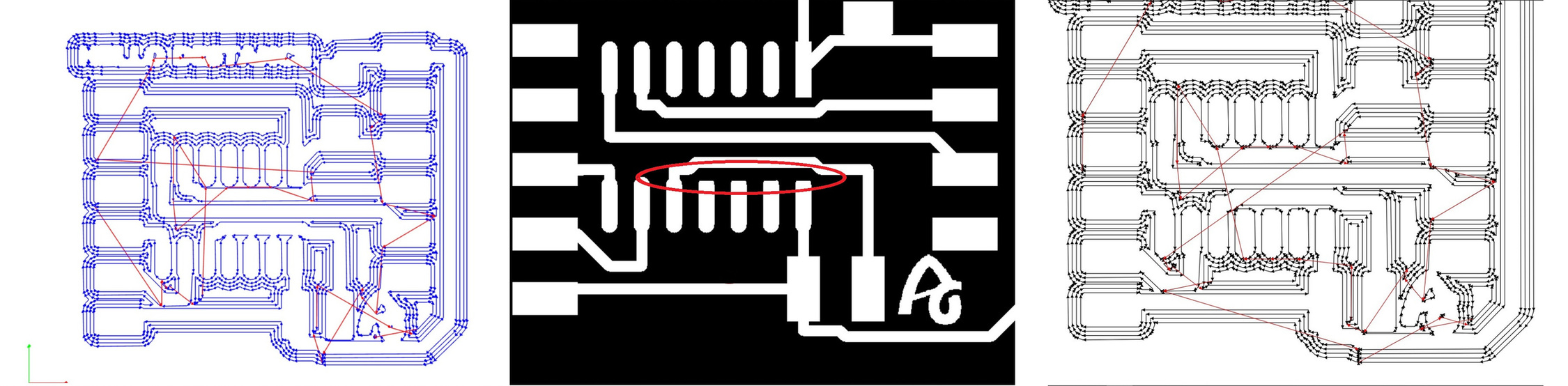
And these are the two images ready to use in the Modela.
Making
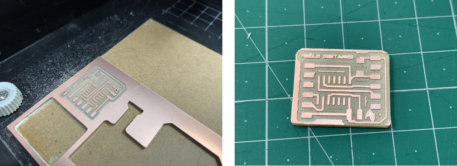
Using Mods CE I milled the board, I reused the last piece of the board that I had milled two weeks ago.
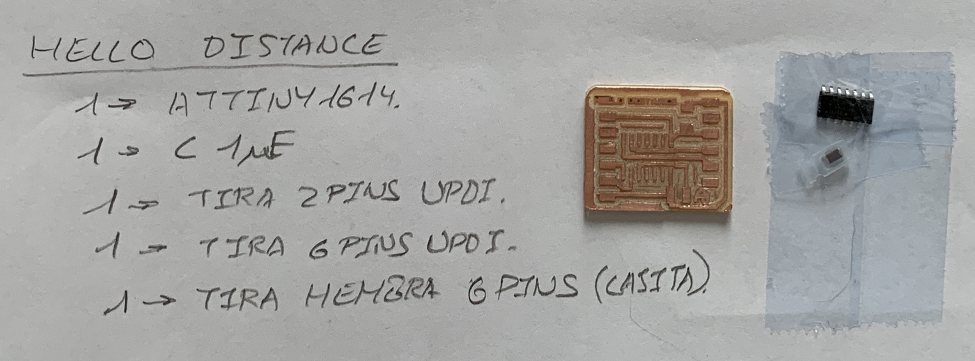
This is the material listing, an ATtiny1614, a 1uF Capacitor and the rest connecting pins.
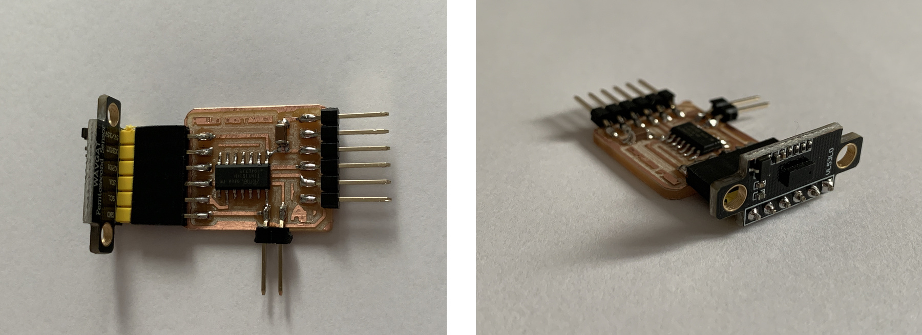
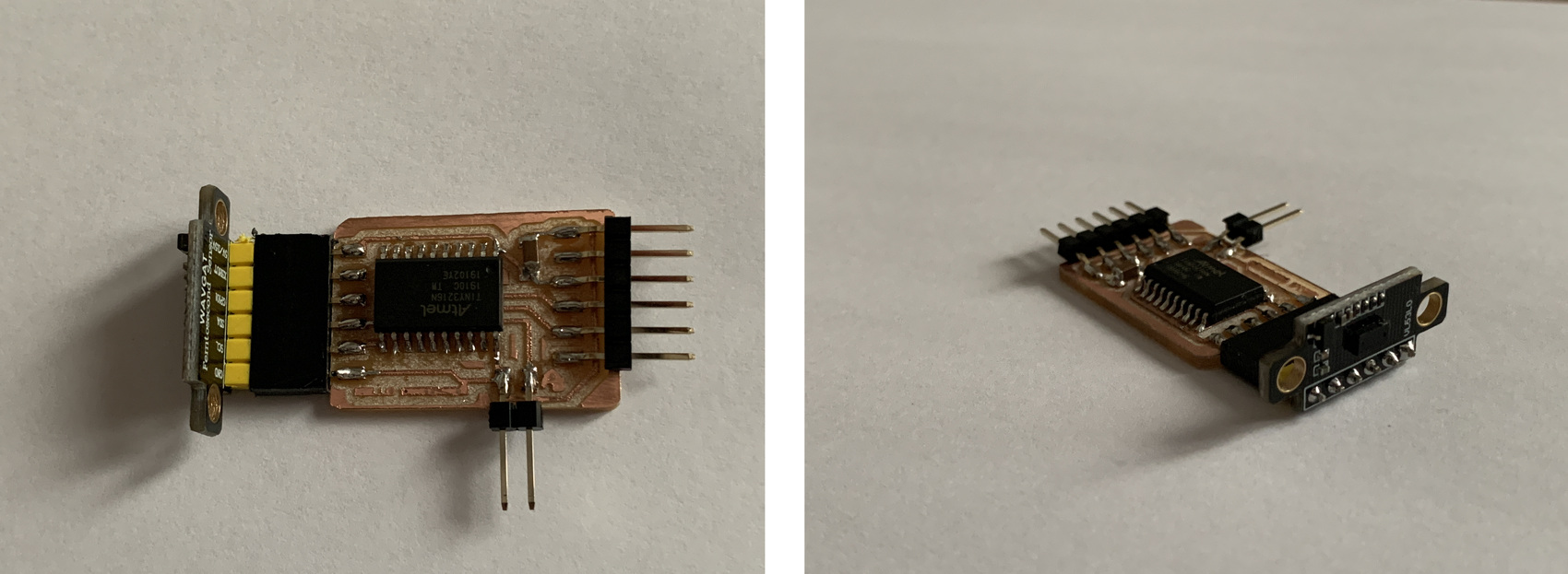
And this is the result of the board, with the VL53L0X module
Programming: Arduino + Linux.
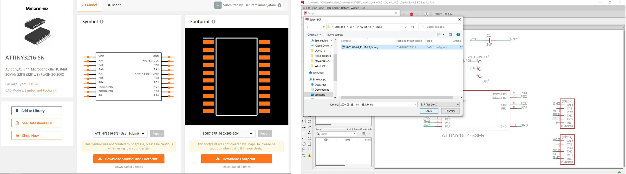
To program the ATtiny1614 I am going to use Arduino and the Luis Llamas program that it has on its page, use the Adafruit library that you can find at this link. I try to download it in the Arduino Library and I can't, it gives me an error. So I decide to uninstall Arduino from Linux and reinstall it again. Meanwhile, I try to do it with Windows and I realize that the program does not enter the ATtiny1614, it occupies 100% of its memory. The Adafruit library is very large. 😭
RECOMMENDATION: Don't try to create the .hex file in Windows and then try to load it in Lynux, because the communication protocol is different; in Linux it is "ttyUSB0" and in Windows it can be "COM4"

So ATtiny1614 does not enter the program or the library. I call Nuria to comment and ask her if she had accidentally ordered the ATtiny3216 and she said yes. Thanks Nuria. 🤗
ATtiny3216
Since last week I looked at the datsheet of the other microcontrollers, this time it's time to look at everyone's "big brother", the ATtiny3216.. I combine the Datasheet image with the one from the SpenceKonde website on the ATtiny3216.
- 20 pin package.
- Internal clocks 1/4/5/8/10/16 20 MHz.
- 32768 bytes Flash Memory.
- 256 bytes EEPROM.
- 2048 bytes SRAM.
- Maximum voltage: 6V; minimum voltage -0.5 V.
After looking at the basic features, you will find the pinning of the microcontroller.
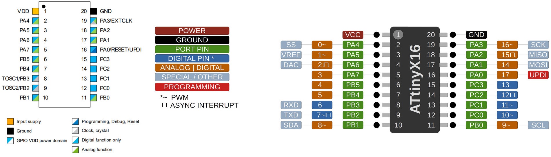
- VDD: Supply voltage.
- GND: Ground.
- Digital pins: Port A: PA0, PA1, PA2, PA3, PA4, PA5, PA6, PA7. Port B: PB0, PB1, PB2, PB3, PB4, PB5. Port C: PC0, PC1, PC2, PC3.
- Analog pins: Port A: PA0, PA1, PA2, PA3, PA4, PA5, PA6, PA7. Port B: PB0, PB1, PB4, PB5.
- UPDI Programming pin: PA0 (physical pin number 16).
All I/O pins can be configured with internal pullup resistance.
Within the communications section there are different types and their pins are different. It is clear that the different communication protocols cannot all be used at the same time, because they have pins in common.
- USART - Universal Synchronous and Asynchronous Receiver and Transmitter: It has the RX (PB3 or PA2) and the TX (PB2 or PA1).
- SPI - Serial Peripheral Interface: It has only MOSI (PA1 or PC2), MISO (PA2 or PC1), SCK (PA3 or PC0), SS (PA4 or PC3) .
- TWI - Two Wire Interface (I2C): It has SDA (PB1 or PA1) and SCL (PB0 or PA2).
Design the new board for the ATtiny3216
Since I had already designed the circuit for the ATtiny1614, I would only have to change it for the ATtiny3216. It seems easy, but ... 😥 There is no footprint. I search Octopart and nothing. At the end I find it on the SnapEDA page.
Once downloaded, I add the library to Eagle.
Once the schematic is done, this is the result of the board.
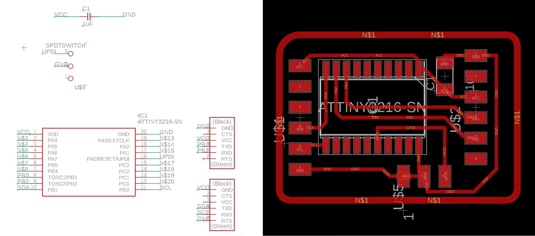
This is the end result of the board. After exporting it as a monochrome image, I use GIMP to create the outer border and erase the paths I don't need from the connectors.
Making
After milling the plates using Mods CE, this is the end result.
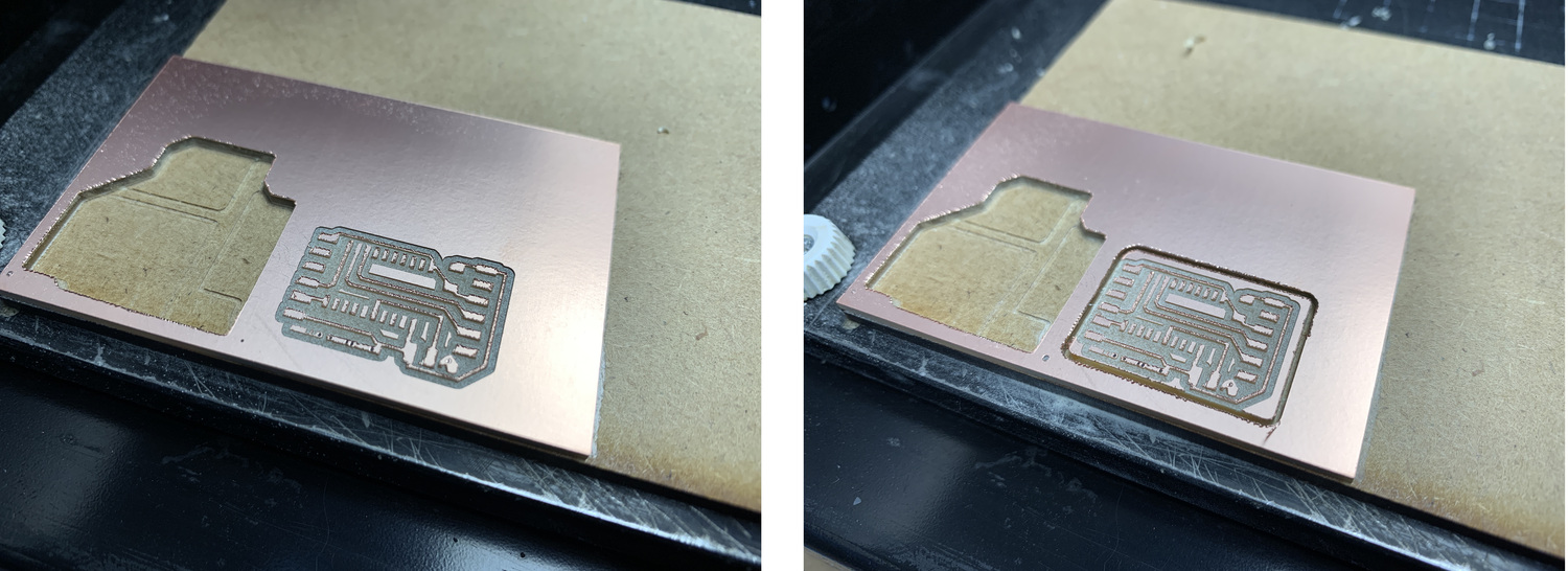
And this is the result of the board, with the VL53L0X module
Programming: Arduino + Linux.
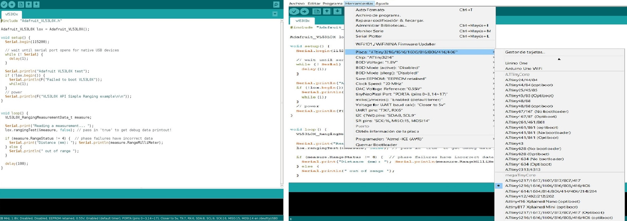
I return to resume the programming of the VL53L0X, but this time Pablo recommends that I use one of the examples that the Adafruit library brings you (it is the first time that I discover that when you download a library in Aduino, it brings associated examples. Incredible). Configure the Arduino for the ATtiny 3216.
Using the PyUPDI and the FT230XS programmer and the converter for UPDI I load the .hex program.
Program the board using python -> run sudo python3 pyupdi.py -d tiny3216 -c /dev/ttyUSB0 -b 19200 -f vl53l0x.ino.hex -v
After, listen the serial port python -m serial.tools.miniterm /dev/ttyUSB0 115200
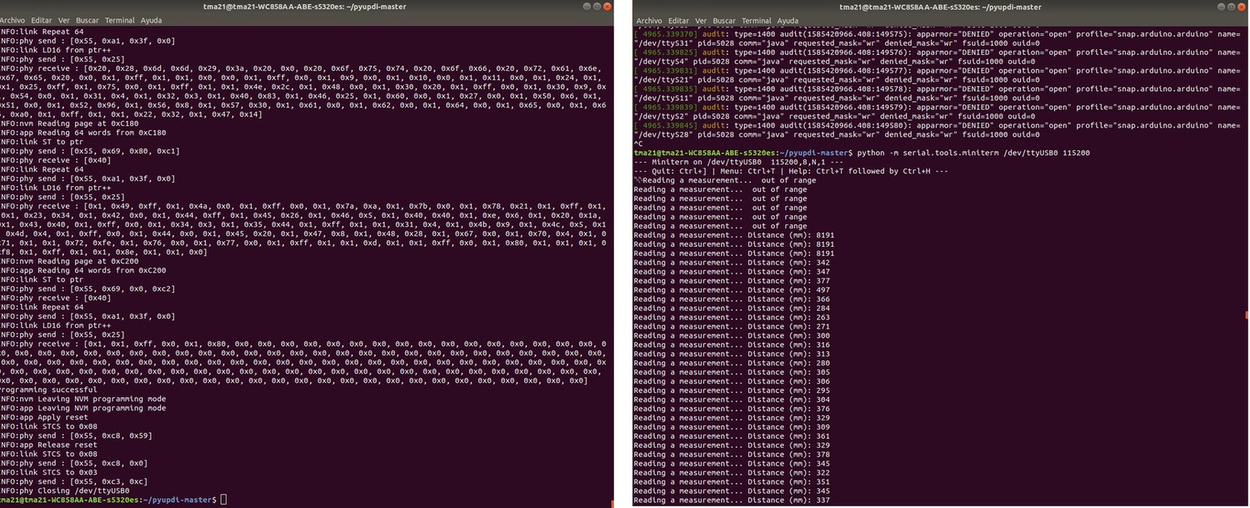
It works and measures well. Here is an example video with the measurements on the screen and with a ruler.
Here is the Arduino code.
//Adafruit VL53L0X program.

//Adrian Torres. Fab Academy 2020.

#include "Adafruit_VL53L0X.h"

Adafruit_VL53L0X lox = Adafruit_VL53L0X();

void setup() {
  Serial.begin(115200);

  // wait until serial port opens for native USB devices
  while (! Serial) {
    delay(1);
  }

  Serial.println("Adafruit VL53L0X test");
  if (!lox.begin()) {
    Serial.println(F("Failed to boot VL53L0X"));
    while(1);
  }
  // power
  Serial.println(F("VL53L0X API Simple Ranging example\n\n"));
}


void loop() {
  VL53L0X_RangingMeasurementData_t measure;

  Serial.print("Reading a measurement... ");
  lox.rangingTest(&measure, false); // pass in 'true' to get debug data printout!

  if (measure.RangeStatus != 4) {  // phase failures have incorrect data
    Serial.print("Distance (mm): "); Serial.println(measure.RangeMilliMeter);
  } else {
    Serial.println(" out of range ");
  }

  delay(100);
}
Here is the files to download.
- ATtiny3216 Library
- Hello Distance Traces ATtiny1614
- Hello Distance Interior ATtiny1614
- Hello Distance Schematic and Board ATtiny1614
- Hello Distance Traces ATtiny3216
- Hello Distance Interior ATtiny3216
- Hello Distance Schematic and Board ATtiny3216
- Arduino program VL53L0X
29/03/2020
My instructor Pablo tells me that there is another library within Arduino, it is from Polulu for the VL53L0X, and it may be smaller and enter the ATtiny1614. The library is here. Thank you Pablo, master of the code. 🤗
I use a code that the library had as an example, it is called "Single."
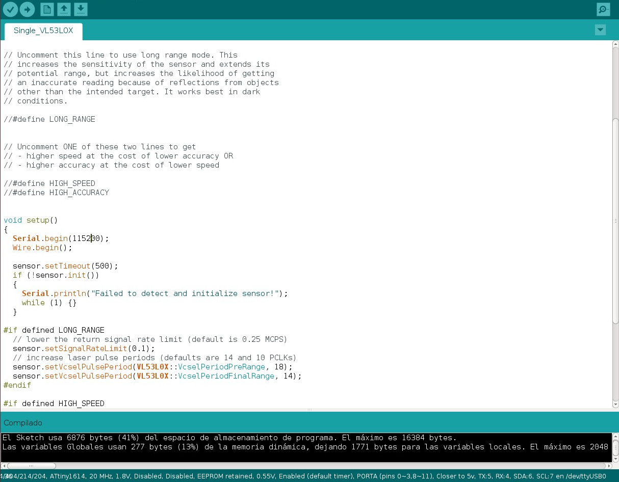
Using the PyUPDI and the FT230XS programmer and the converter for UPDI I load the .hex program.
Program the board using python -> run sudo python3 pyupdi.py -d tiny1614 -c /dev/ttyUSB0 -b 19200 -f Single_VL53L0X.ino.hex -v
After, listen the serial port python -m serial.tools.miniterm /dev/ttyUSB0 115200
The data is better seen on video.
Here is the Arduino code.
/* This example shows how to get single-shot range
 measurements from the VL53L0X. The sensor can optionally be
 configured with different ranging profiles, as described in
 the VL53L0X API user manual, to get better performance for
 a certain application. This code is based on the four
 "SingleRanging" examples in the VL53L0X API.

 The range readings are in units of mm. */

#include
#include

VL53L0X sensor;


// Uncomment this line to use long range mode. This
// increases the sensitivity of the sensor and extends its
// potential range, but increases the likelihood of getting
// an inaccurate reading because of reflections from objects
// other than the intended target. It works best in dark
// conditions.

//#define LONG_RANGE


// Uncomment ONE of these two lines to get
// - higher speed at the cost of lower accuracy OR
// - higher accuracy at the cost of lower speed

//#define HIGH_SPEED
//#define HIGH_ACCURACY


void setup()
{
  Serial.begin(115200);
  Wire.begin();

  sensor.setTimeout(500);
  if (!sensor.init())
  {
    Serial.println("Failed to detect and initialize sensor!");
    while (1) {}
  }

#if defined LONG_RANGE
  // lower the return signal rate limit (default is 0.25 MCPS)
  sensor.setSignalRateLimit(0.1);
  // increase laser pulse periods (defaults are 14 and 10 PCLKs)
  sensor.setVcselPulsePeriod(VL53L0X::VcselPeriodPreRange, 18);
  sensor.setVcselPulsePeriod(VL53L0X::VcselPeriodFinalRange, 14);
#endif

#if defined HIGH_SPEED
  // reduce timing budget to 20 ms (default is about 33 ms)
  sensor.setMeasurementTimingBudget(20000);
#elif defined HIGH_ACCURACY
  // increase timing budget to 200 ms
  sensor.setMeasurementTimingBudget(200000);
#endif
}

void loop()
{
  Serial.print(sensor.readRangeSingleMillimeters());
  if (sensor.timeoutOccurred()) { Serial.print(" TIMEOUT"); }

  Serial.println();
}
Final Project Test
Phototransistor + Train
I do a little test with the visible light phototransistor, to see how the values behave when the train passes. When it passes over it has very low values between 10 and 0.
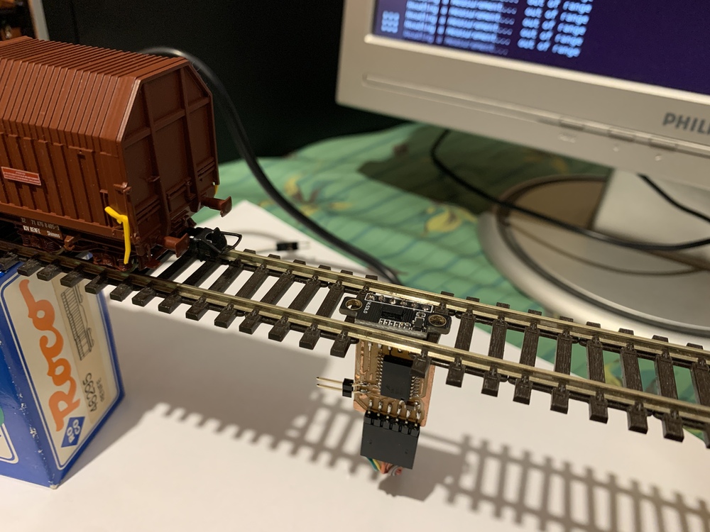
VL53LOX + Train
With the time of flight sensor, when it is placed on the track it is out of range, but when the train passes over it gives me values below 40 mm.
In this image you can see in better detail the placement of the VL53LOX sensor between the track, to detect the passage of the wagon. It's just a test. 😅
Review of the class
During the review of this class I volunteered with the FPGA in the minute 1:20:30. 😊
20200401 input devices review from Academany on Vimeo.
Files
Find below the files that I made for this assignment.
- ATtiny1614 Library
- Hello Reflect Traces
- Hello Reflect Interior
- Hello Reflect Schematic and Board
- Arduino program Hello Phototransistor
- Arduino program Hello Reflect IR
- ATtiny3216 Library
- Hello Distance Traces ATtiny1614
- Hello Distance Interior ATtiny1614
- Arduino program Single_VL53L0X
- Hello Distance Schematic and Board ATtiny1614
- Hello Distance Traces ATtiny3216
- Hello Distance Interior ATtiny3216
- Hello Distance Schematic and Board ATtiny3216
- Arduino program VL53L0X