Week 17- Machine design
Overview
For this week we have two assignments:
- Group assignment
- Individual assignment
- Design a machine that includes mechanism + actuation + automation
- Build the mechanical parts and operate it manuall
- Actuate and automate your machine.
- Document your individual contribution.
Have you?
Documented the machine building process to the group page.
Documented your individual contribution to this project on your own website.
Linked to the group page from your individual page as well as from group page to your individual pages.
The Process
This week is about how to manage to work as a part of a team and master the skills needed to collaborate with others. So we choose to have a little fun, yes we still in the panademic version of the academy but this is our last assignment so lets try to take it easy and make something happy =)
At the beginning we have a lot of ideas, but we decided to create an Egg Plotter, based on arduino, 2 stepper and 1 servo motors. In this page I will ONLY document my individual contributions within the team to create the machine, but the overall view about the machine and the tasks performed can be found in Our Super 2 Days Assignment.
My contribution
My contribution was in in the automation phase and in the integration part, in which I was responsible for:
- Design the a motor drive pcb to interface 2 Nema-16 and servo motor with the Arduino
- Assembly and test with Mans
- Group Documentation with Row'a
The Steps:
1) Motor drive specifications and system analysis
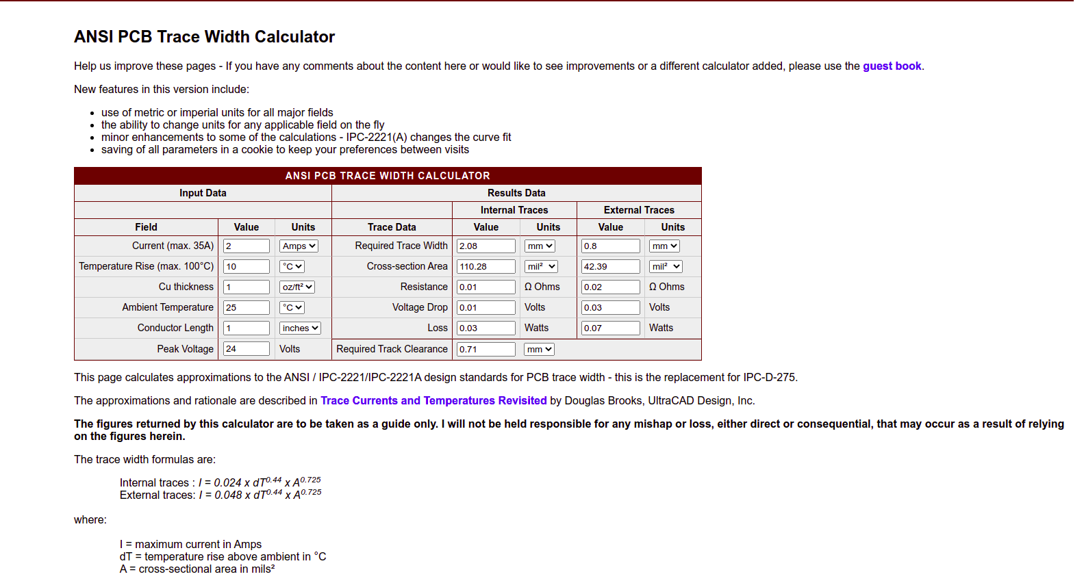
Specifications (Electrical)
- Minimum output drive capacity = 12V and 1A.
- Input signal from any Microcontroller = 5V or 3.3V
- Use 1 A4982 microstepping driver to operate bipolarsteppermotor Nema-16
- Assume in all power calculation that copper layer is only “1 oz thickness”
Specifications (Mechanical)
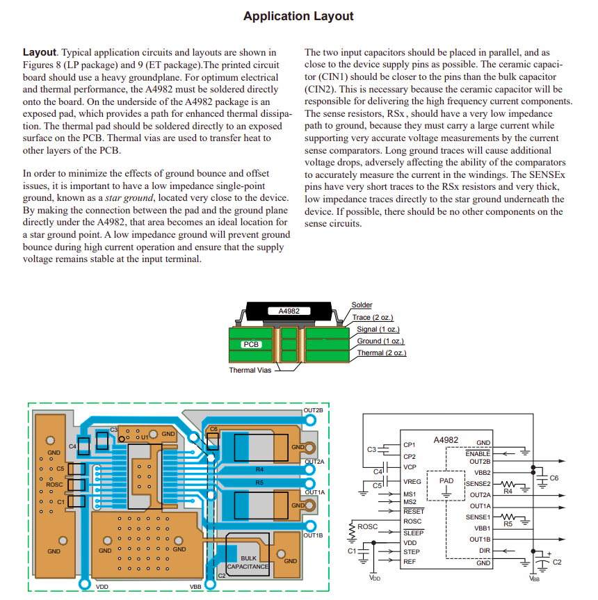
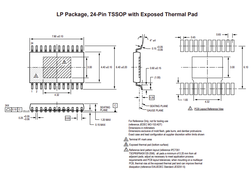
- Use 24-pin TSSOP with exposed thermal pad For A4982
- Board dimensions 2.5*1.5cm with curved angels
- Add heat sinks in pcb layer.
2) Block Design

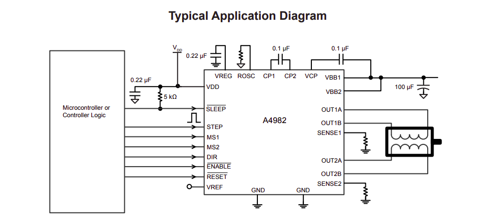
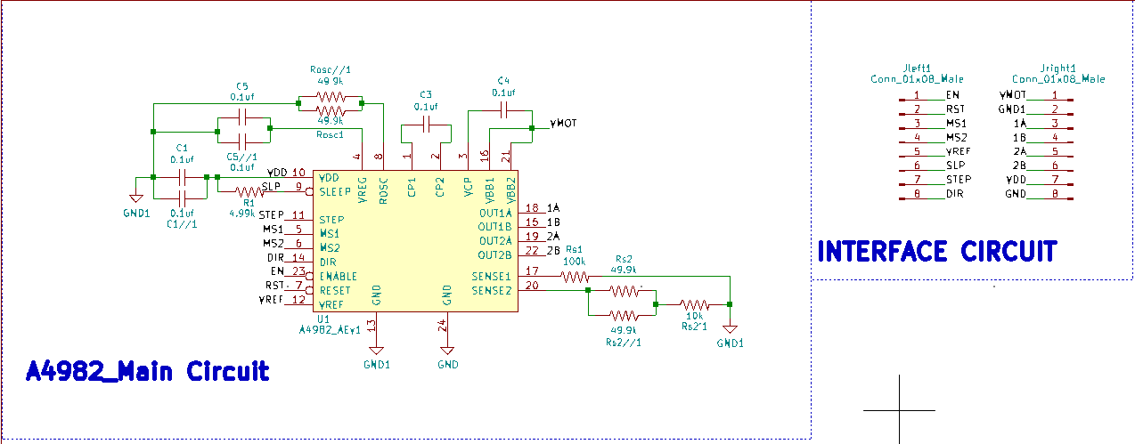
3) Circuit Design
your number one friend through this step is the datasheet. so let's have a quick tour in A4982 datasheet
A4982 Specifications
Circuit Components
4) Schematic Design using Kicad
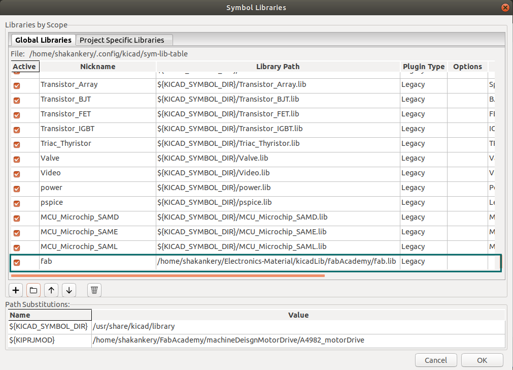
Download Fab-library:
you can find a fab-library with all the inventory component Here. download it then create a folder wherever you want for kicad folder to be kept.
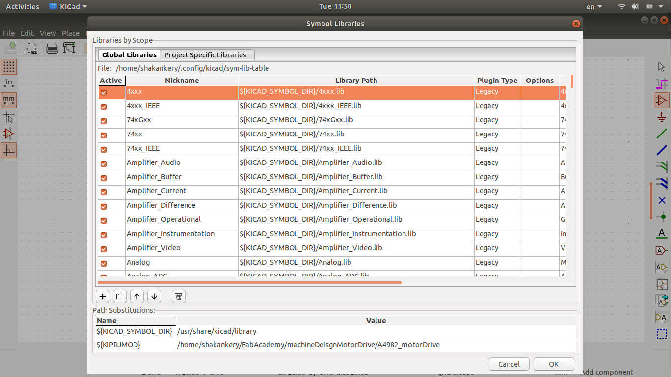
I've notice that the main component of the circuit A4982 is missing from fab Fab-library
so I download digikey-kicad-library and
following the same
steps, yet I face tham same issue so I will need to deisgn the symbol library from scratch.
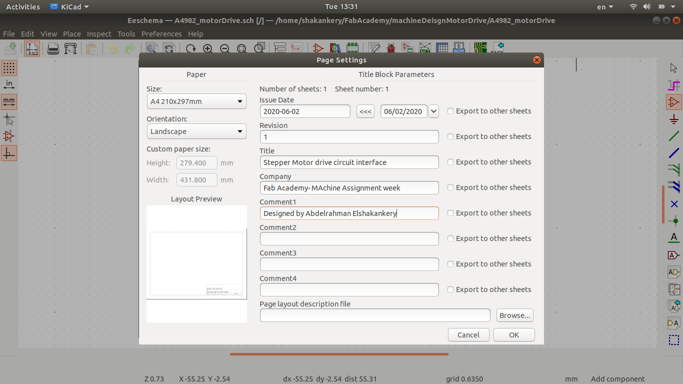
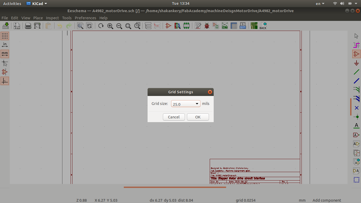
Page setup:
add the design information and the schematic Grid setting
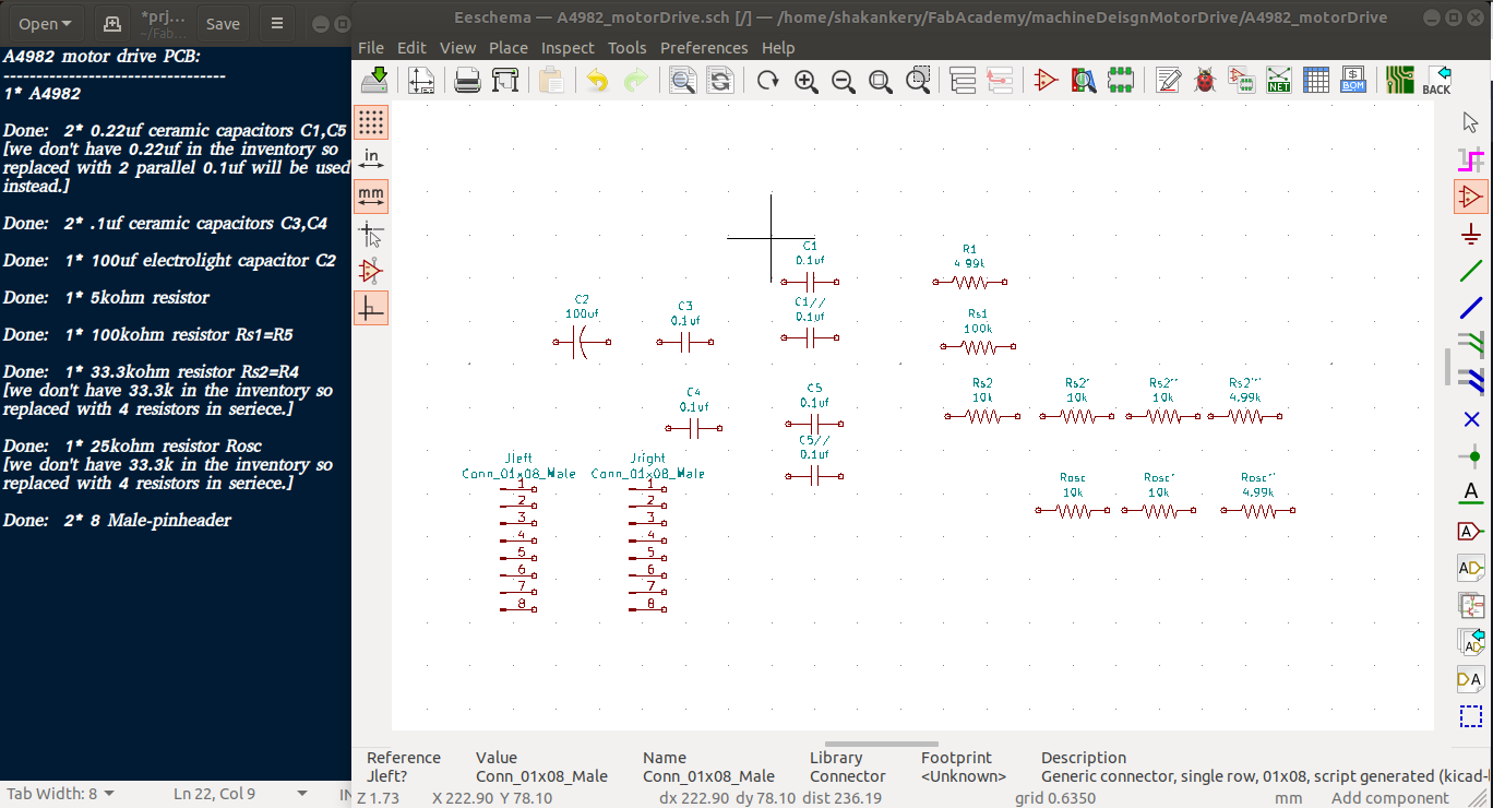
Symbols:
add symbols to the sheet and create symbol if needed
along side that I open our flinc-inventory-sheet to make sure we have the same values of the components I need.
we don't have all the components that I need so I tweak the design a little and updated the text file.
Circuit Components
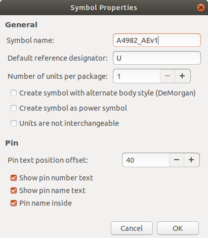
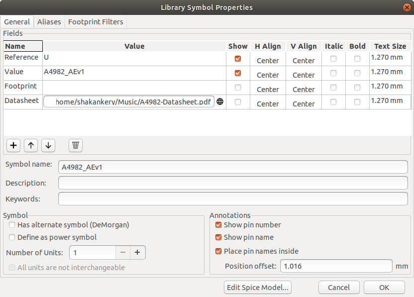
from Kicad I choose symbol editor then I create a new library called machineDesign and select the symbol properties to give our symbol it's identity
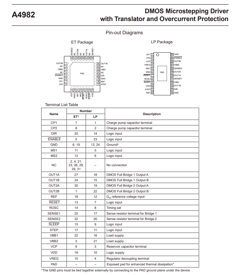
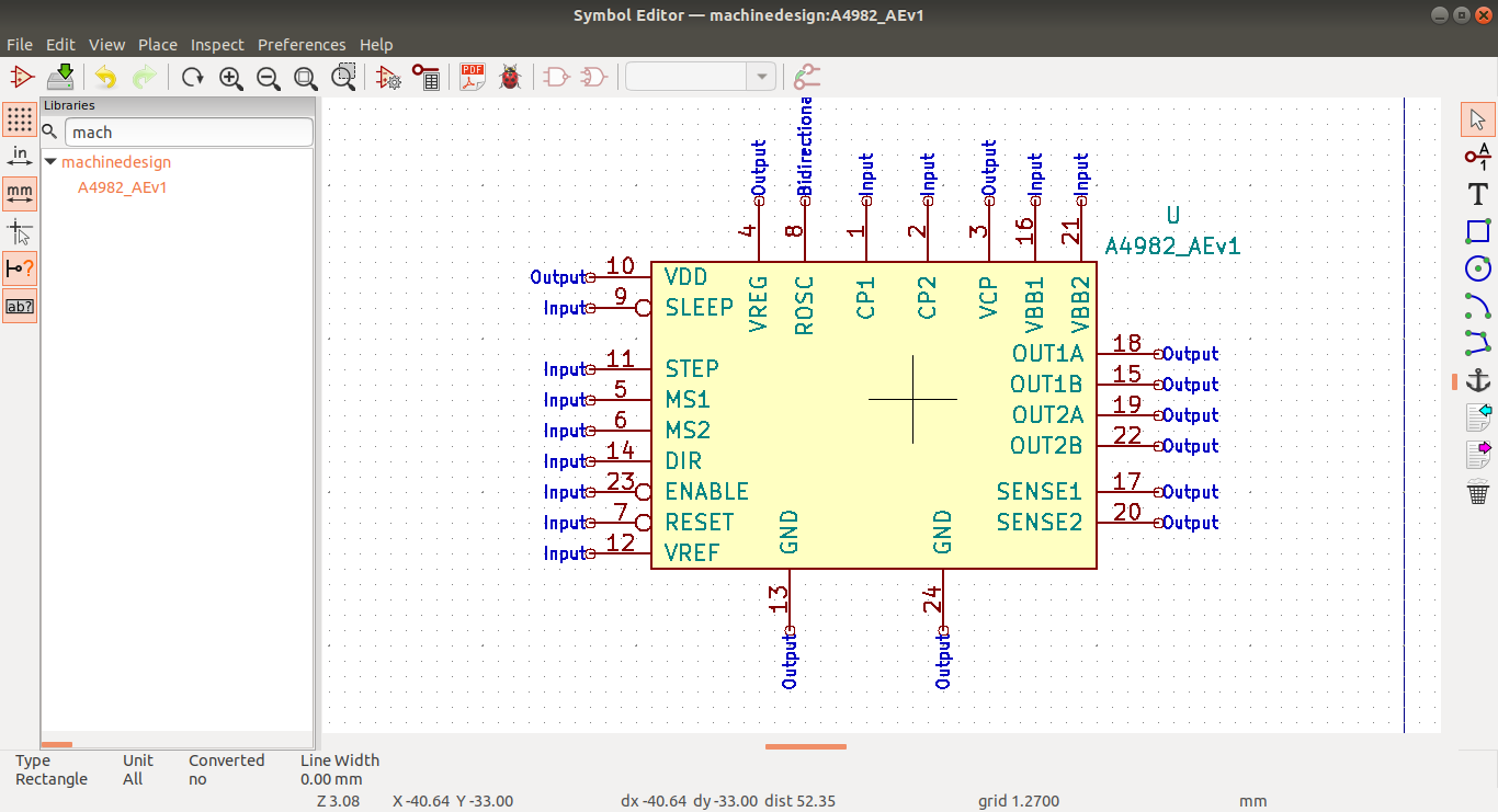
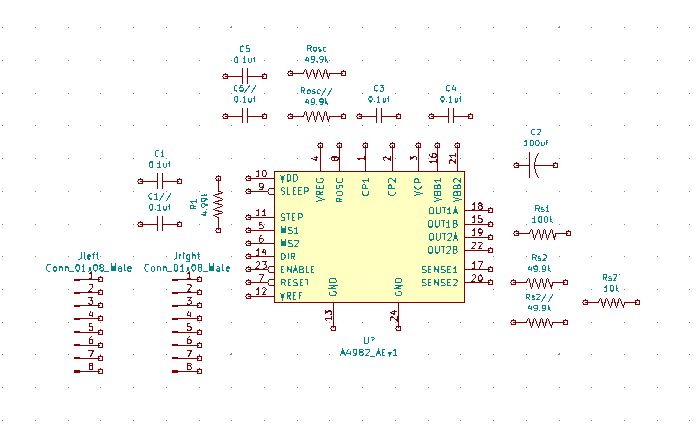
we go back to the data sheet to get the pinout assignment in order to create our A4982 symbol
please find this Reference designator-wikipedia as a reference
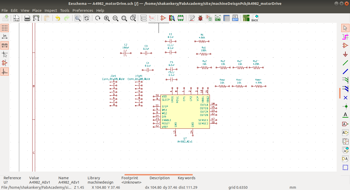
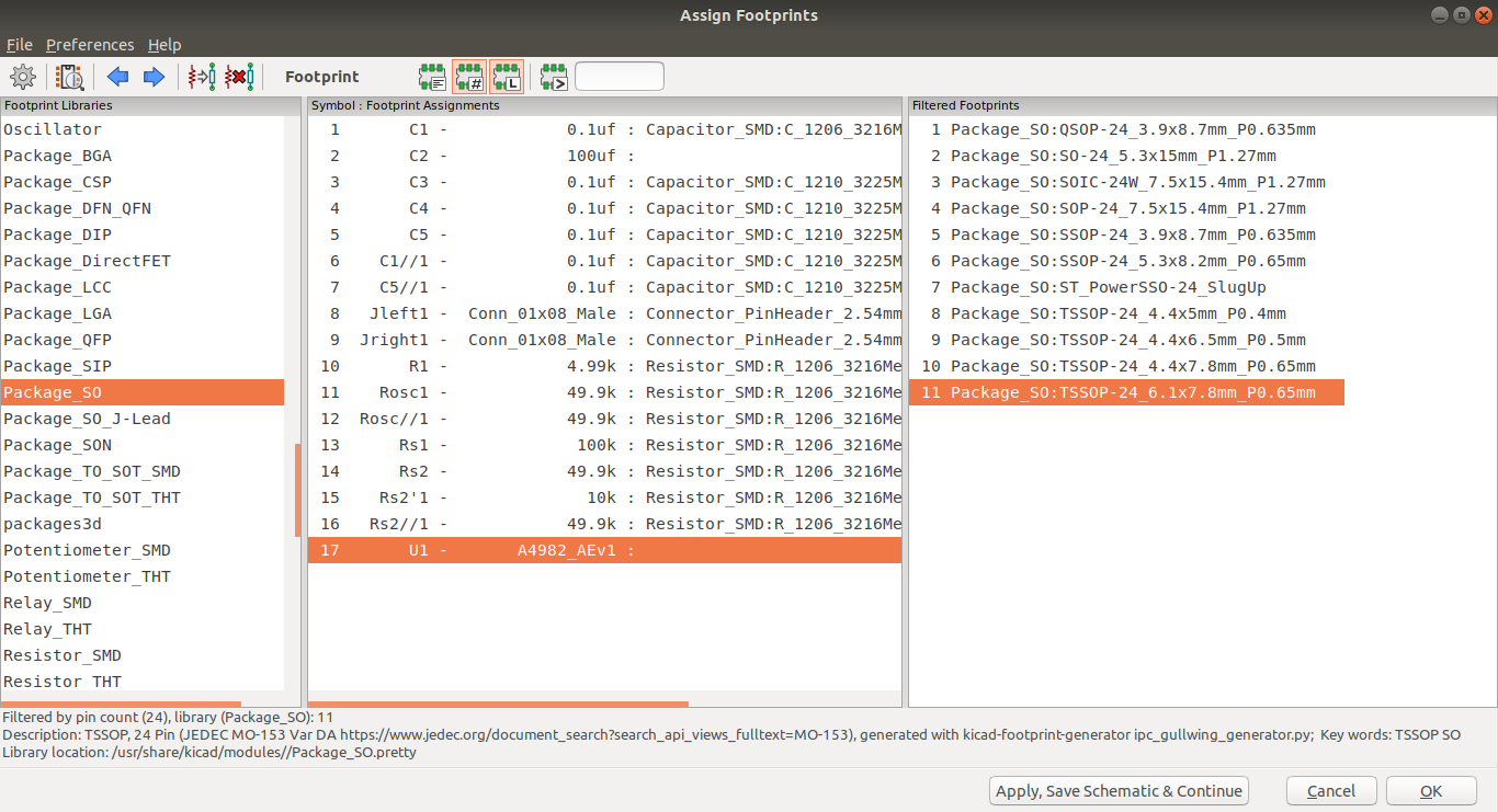
Arrange, Annotate, Associate:
arrange, annotate symbols and associate with footprints
Circuit Components final
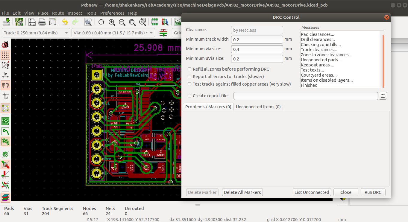
Wiring, Nets, Electrical Rules Check, Comments and Netlist generator:
final steps and edits to the schematic
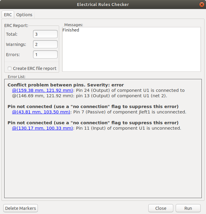
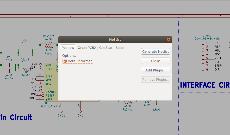
This step is really important in order to connect the schematic with PCBnew in which we will going to create the PCB layout.
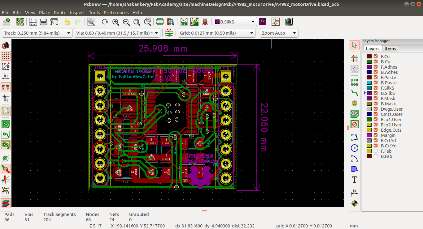
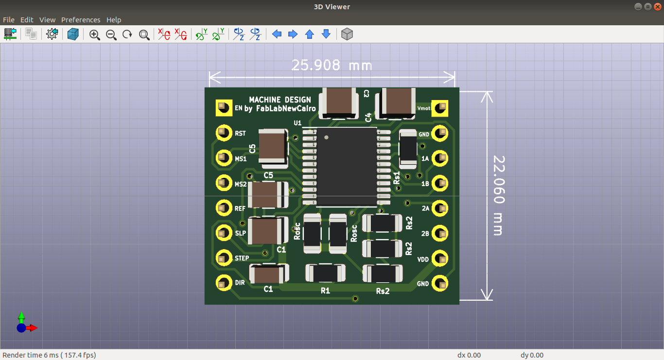
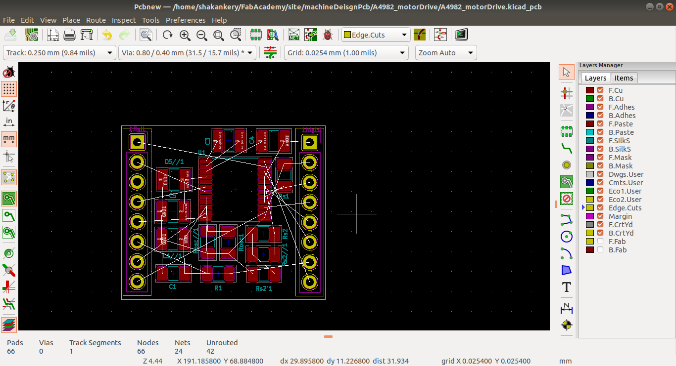
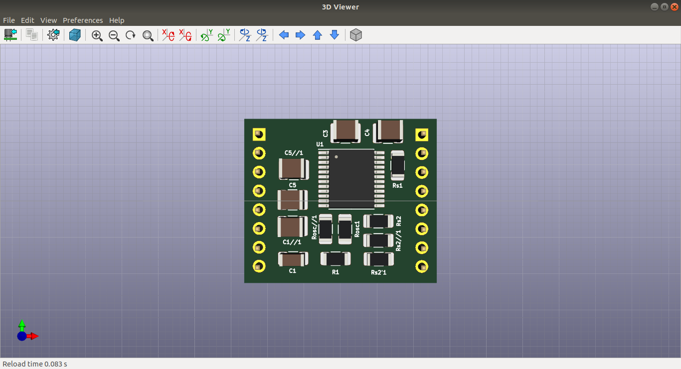
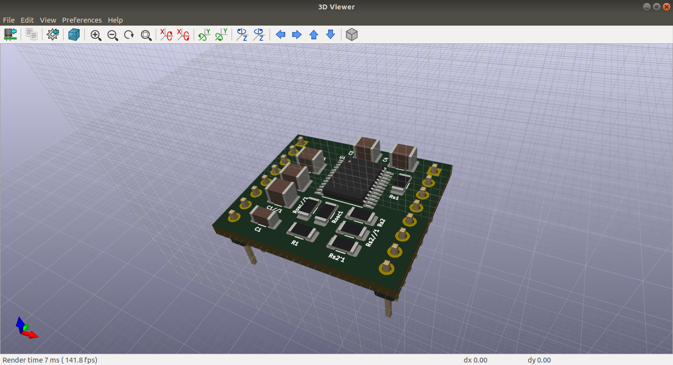
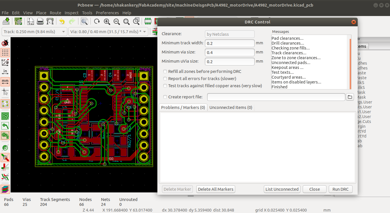
5)PCB layout
Page setup:
add the design information and the schematic Grid setting
Board Outlines + Component placment:
define the size and shape of the board , arrange the components in functional group starting with user
interface
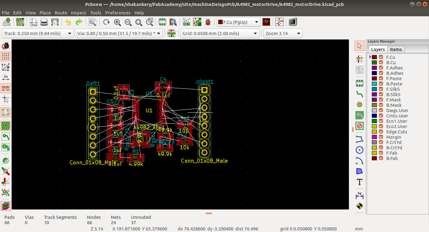
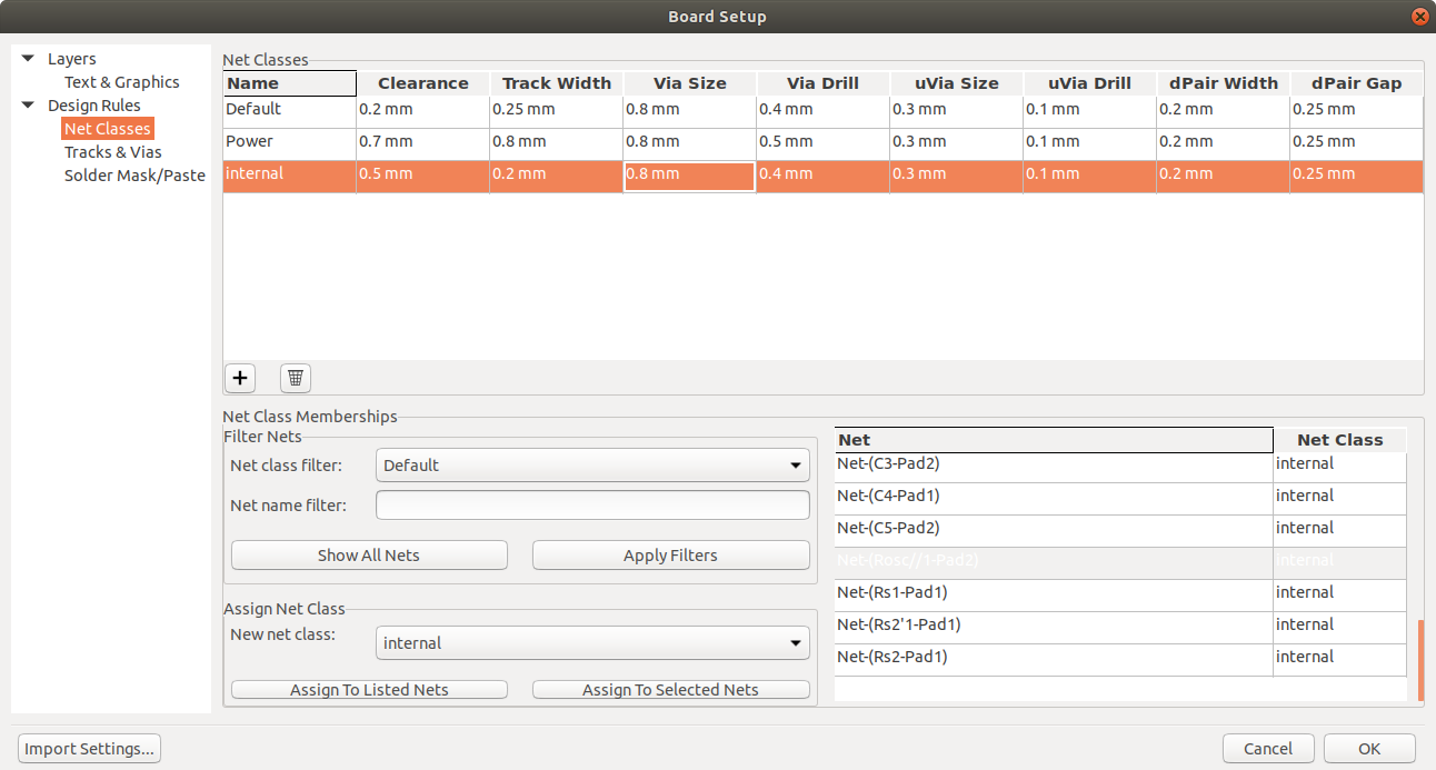
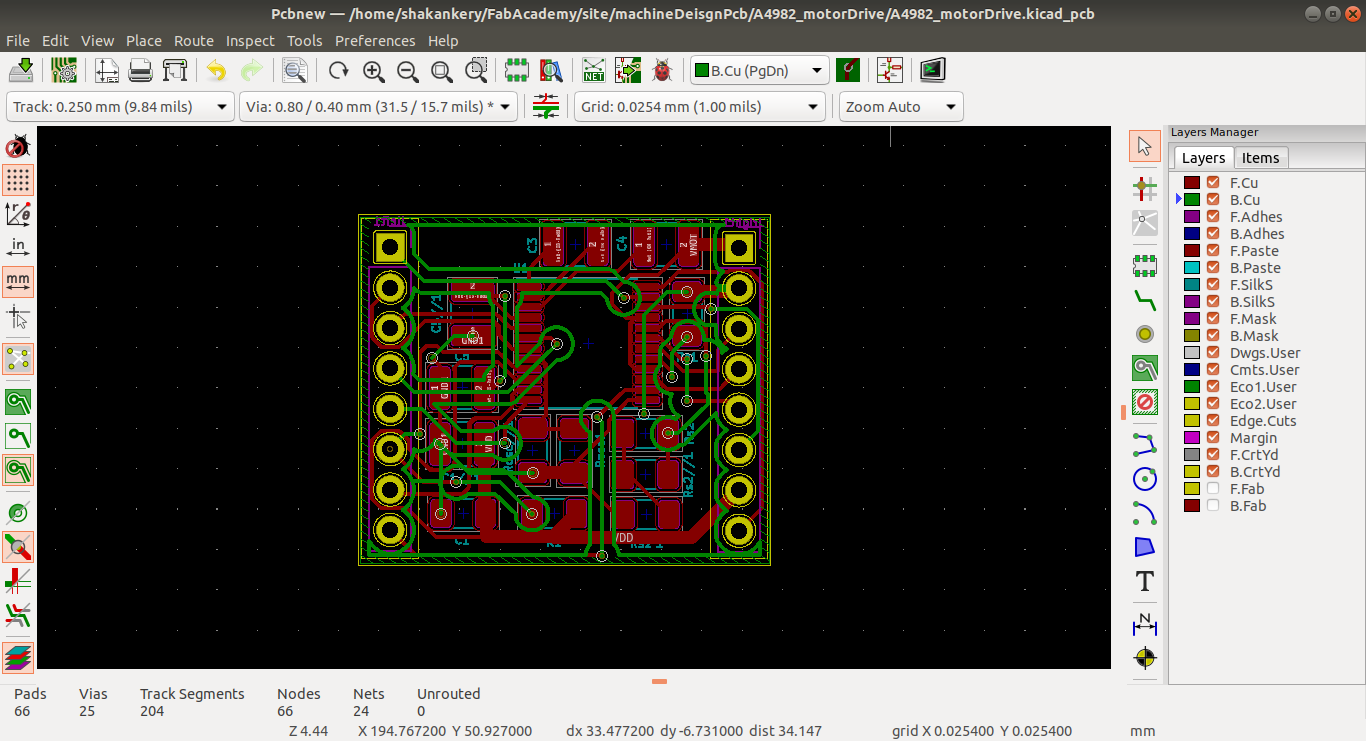
Routing, Copper fills:
routing the component starting with powerthen create a GND fill
Silkscreen and Dimensions: