
week4 - 2020.2.26
5.Electronics Production
Objective: Characterize the design rules for my PCB production process; make an in-circuit programmer by milling and stuffing the PCB, test it, then try other PCB processes.
First of all, I choose to mill the PCB board using the Roland SRM-20. There are other ways to make the PCB board, like through vinyl cutting, laser cutting, electroplating, sewing, and so on.
To do so, we need to prepare the PNG files for milling, and download the according softwares. Since my computer is windows 10, I download WinAVR and firmware (download firmware).


For milling, the material we use is a laminate sheet with a very thin layer of copper. Other choices will be FR1, FR4 boards, etc. we double tape the bottom of the laminate sheet with copper and put it into the Roland SRM-20, so that it doesn’t move.
Then, change the endmill. There are two steps for milling. First, engrave the traces, then cut out the board. The processes needs different endmills. So we set up the 1/64 endmill for engraving.
In order to upload the PNG files, you need to change the format to rml using fabmodule, so that you can inform the machine how to operate the tracing or cutting. I follow this tutorial for all the inputs of the parameter. Then click calculate.

Before milling, you have to make sure the endmill placed right on top of the board.
Mistakes I made:
When I was screwing the endmill, I left a large proportion of it exposed outside the machine. My instructor saw it and stopped the machine. He moved the z axis upward and the endmill fell out. I should lower the z axis more so that the endmill will be fixed into the machine.
Warning:
hold the endmill with your finger when setting it into the machine, otherwise it will lift up a little bit.
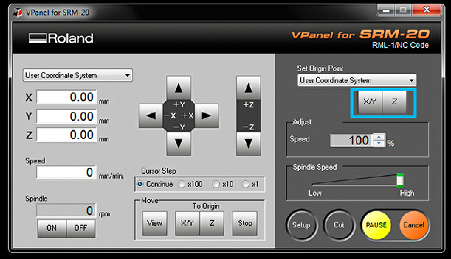
Set the origin points for later cutting.
Warning:
When you adjusting the axis, leave the z axis untouched the surface. Otherwise, the endmill and the board will cause friction when moving around and both will be damaged.
Press cut and choose the file.


Cutting the board is pretty much the same. Change the endmill, change the format with correct inputs, go to the origin point, and cut.

Debur the board. Keep the trace clean.


Check if the circuit go well. If two parts are connected, the machine will ring.

Now, start stuffing, or soldering, the components on the board. The components that we are supposed to stuff are told and given to us from the beginning. We just solder them accordingly. Here is the file.

Tips:
You want to start the soldering from the center of the board, so that it won’t get into your way later.
You can tin the pad with solder first, then place your component on the pad. It’s easier than tin the solder on the component directly.
When selecting a component, put the rest back into the right place. Otherwise, you will mix them up, since they look very small and similar.
In a successful soldering, the solder should look round and shiny.
Test it again if it works properly.

And repeat the steps throughout the whole process.

After finish soldering, we try to program the PCB. First, I unpack and setup firmware in my computer.

Then we sort of connect my PCB(with the help of the packing that our instructor left it after he finished his dessert for lunch) to another computer and PCB, and all the way to my laptop.

But when we type make flash, it doesn’t work. I recheck it and solder some places again, but the connection is correct, but it still doesn’t work. Our instructor suggests us to make a new one, but we don’t have enough time to do so that day. But we diagnose that the problem comes from the soldering.

Downloadable Files