Week6 – 2020.3.10
7.Electronics Design
Objective:
redraw an echo hello-world board;
add (at least) a button and LED (with current-limiting resistor);
1.Redraw an echo hello-world board
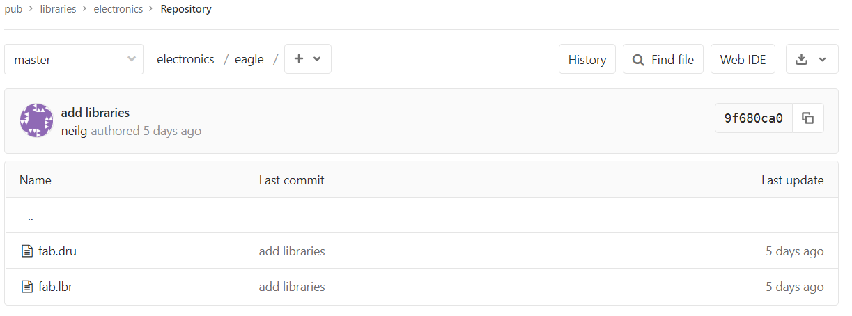
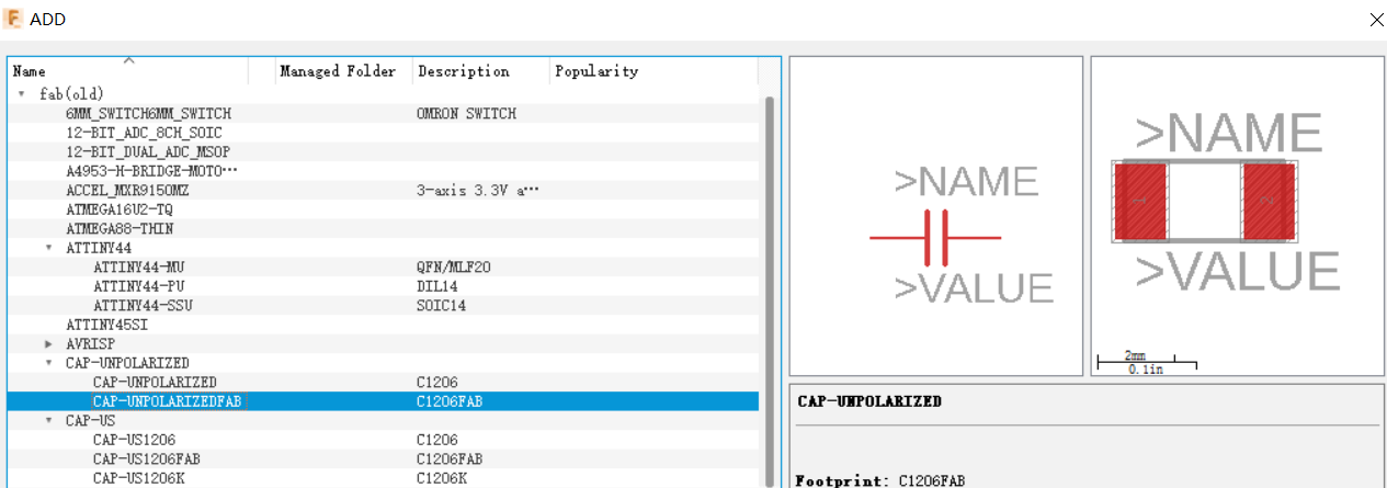
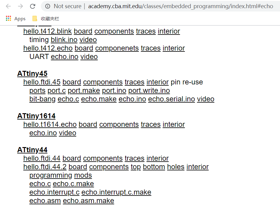
We decide to use Eagle to draw our board. But first of all we have to choose the components we will include in our board. Many of them is saved in a specific file uploaded by Neil. We can find the file by a link of this week’s syllabus. Click libraries, and look for fab.lbr file.
Ok. Now open Eagle. There are two ways you can do that. One is open fusion 360 and use Eagle inside fusion, or you can download Eagle separately. The interface is different. It is suggested to use the separate version of Eagle, because the Eagle in fusion 360 runs slow on some computers, and will cause some unknown problems. it also cannot export your project as in png format. But for some convenience reasons, I choose fusion 360, and after finish drawing my board, I actually have to first open it again in Eagle of the separate version, then export it as a png file.
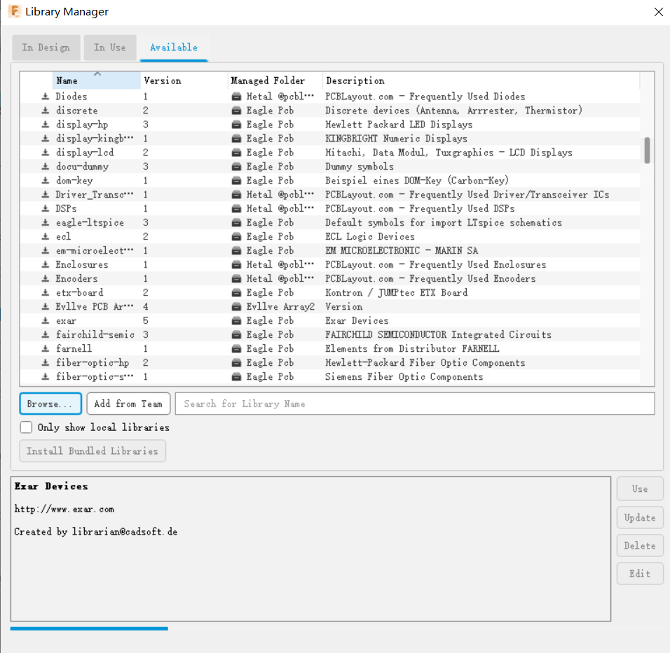
After open Eagle, you have to import the fab.lbr file into your Eagle’s library. In this step, we also confront a difficulty. The file, for some reasons, don’t show up in the library. We fix that by uploading an older version of the file that our instructor has, and it works. Press “Use”, and the file should show up in “In Use” tab.
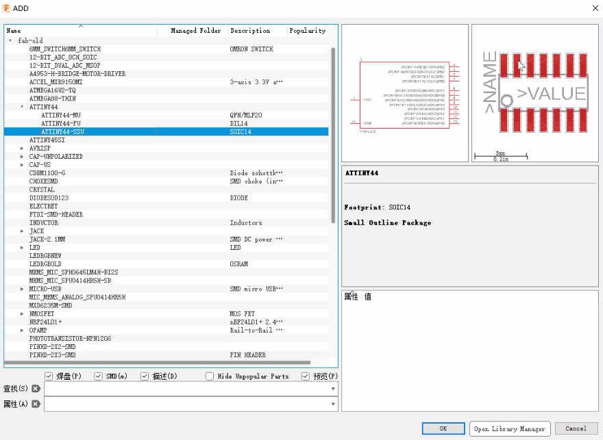
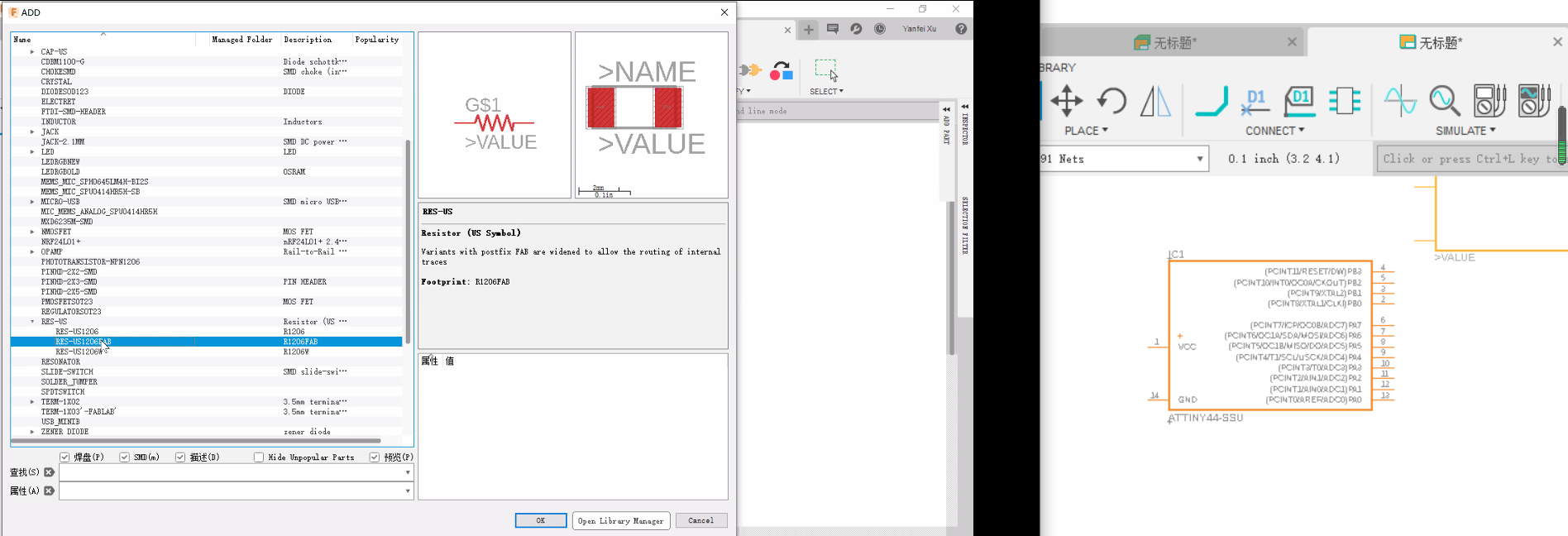
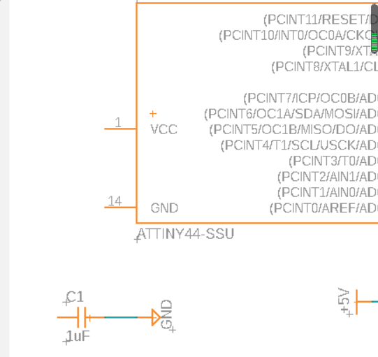
Now, you should see all the components under “fab” when you start adding parts for your board. First choose the ATtiny 44 as shown in the image.
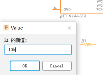
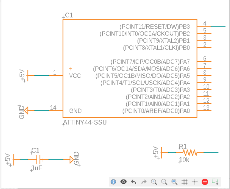
Then, add a resistor and set the value to 10k.
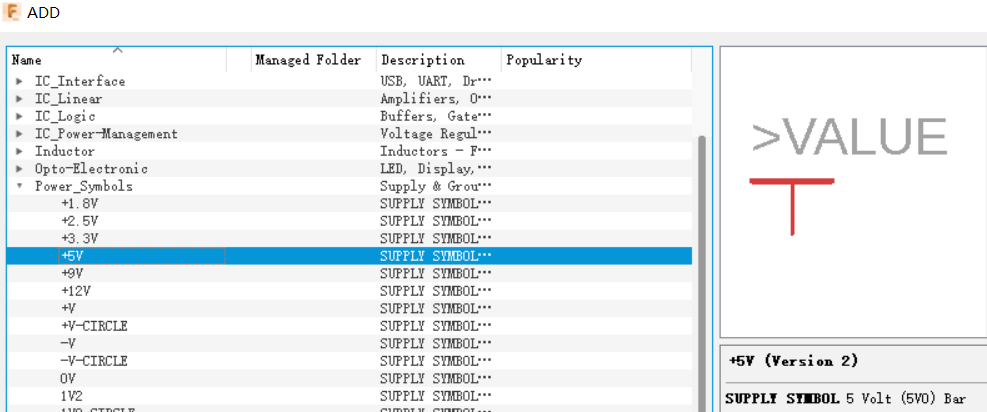
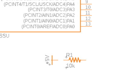
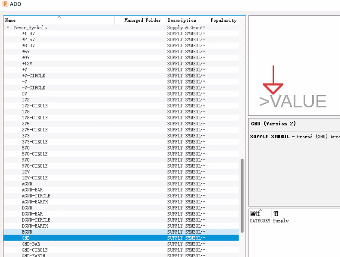
Add 5V bar in one end and name RST by right clicking in other end and the terminal 4 of the ATtiny 44.
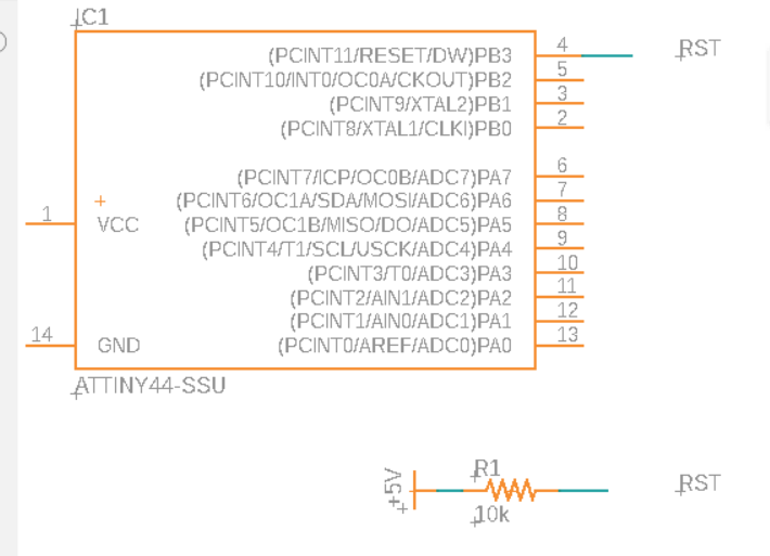
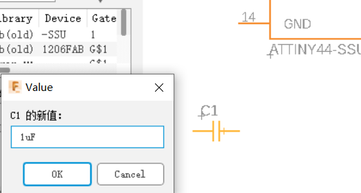
Add capacitor
Connect the capacitor and the resistor with ATtiny 44.
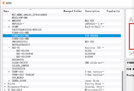
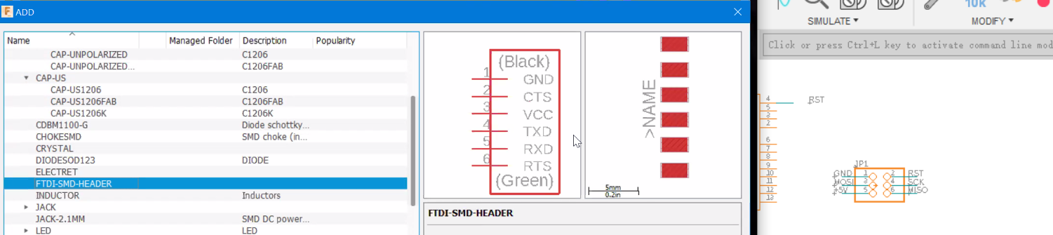
Add pin header and FTDI header
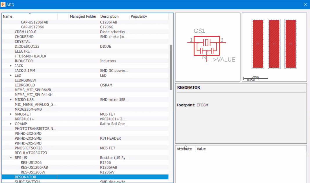
Add resonator.
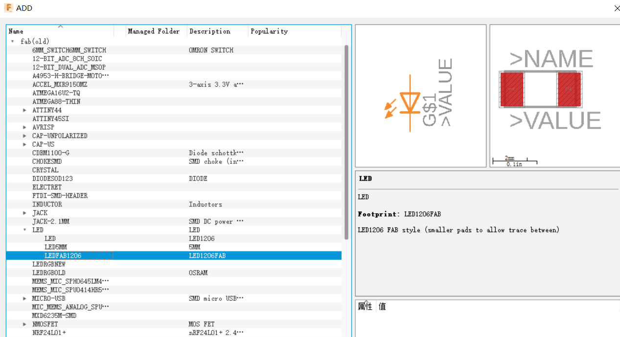
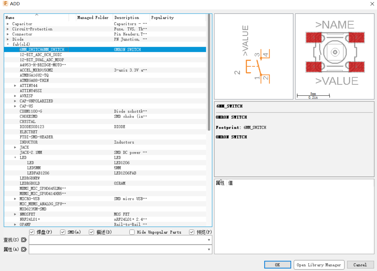
Add LED and Button.
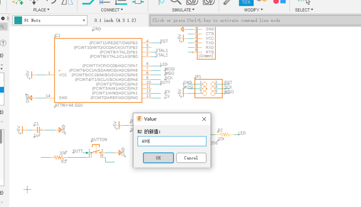
We also need a resistor set beside LED, and set the value of the resistor to 499.
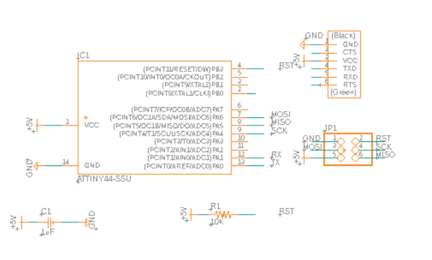
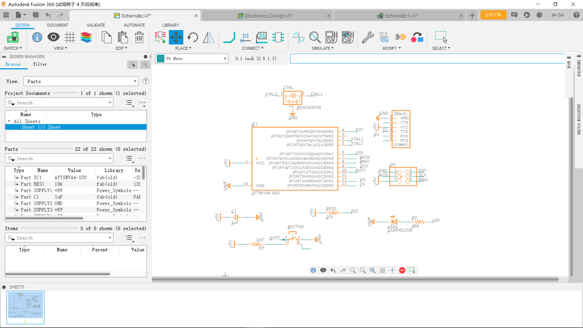
Connect them finally like this.
Click switch in the up left corner to view PCB board and start arranging like the one shown below.
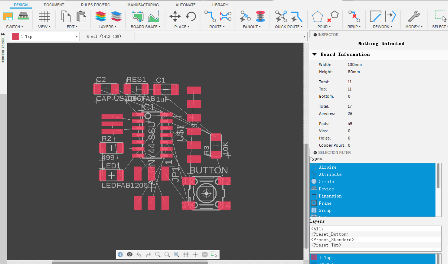
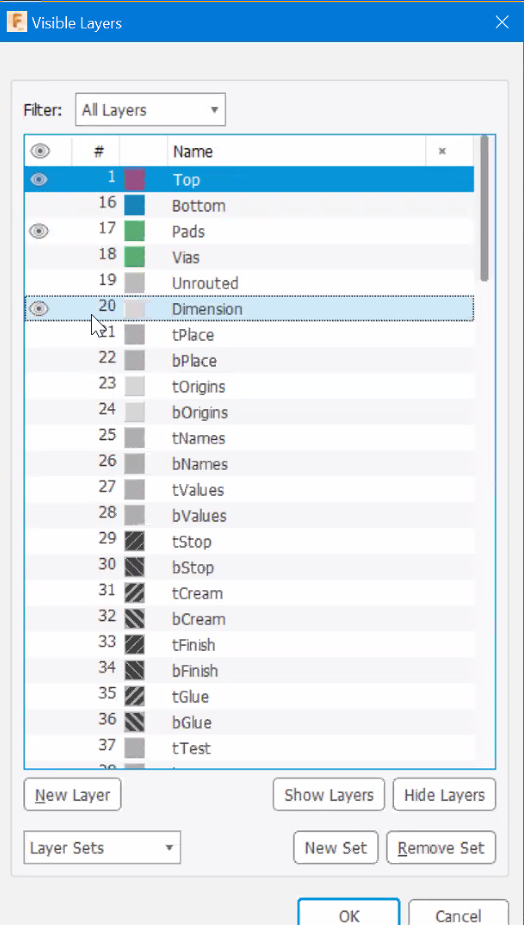
Clear the unwanted symbols by only showing the top and bottom layers.(ignore the traces)
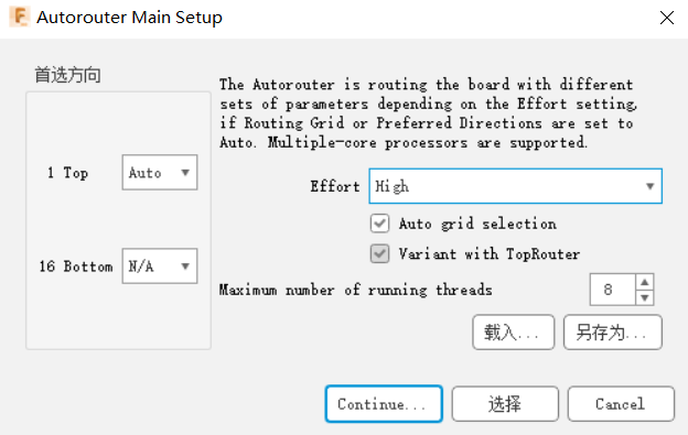
Click autorouter under QUICK ROUTE, select as below and click continue.
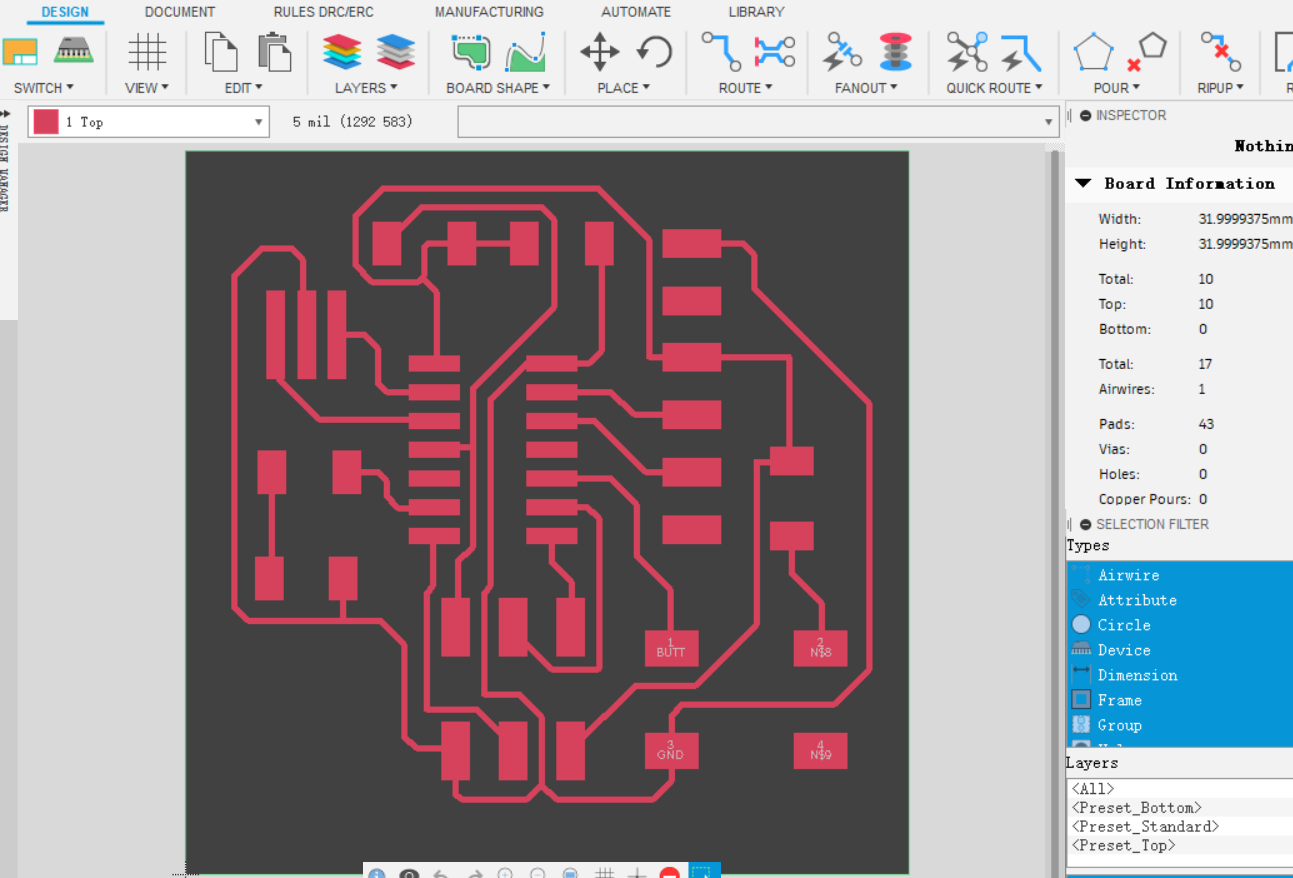
It will give you something like this. Arrange the traces, so that they don’t cause troubles, like being too close to each other.(ignore the board for now)
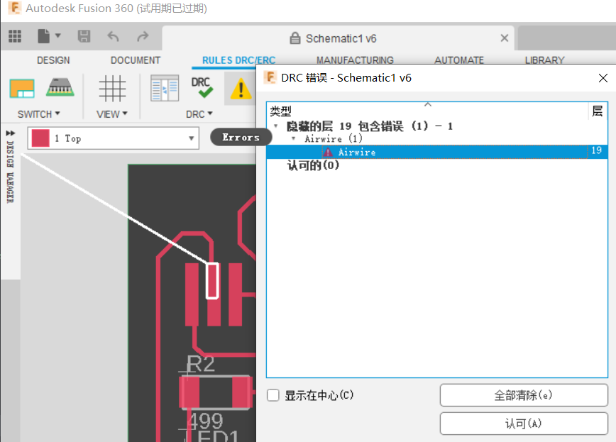
You can also check error of your schematic by clicking error. AIRWIRE is an error when there’s no connection. Since I don't see a lack of connection in the trace, I will leave this error for now.
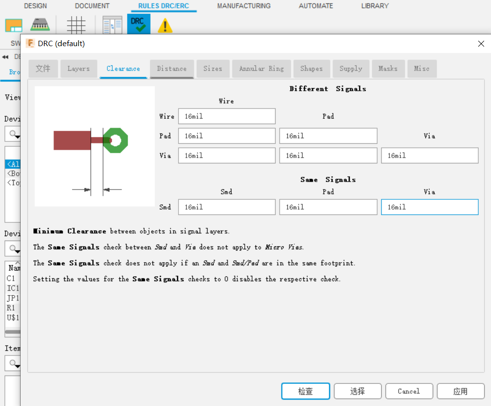
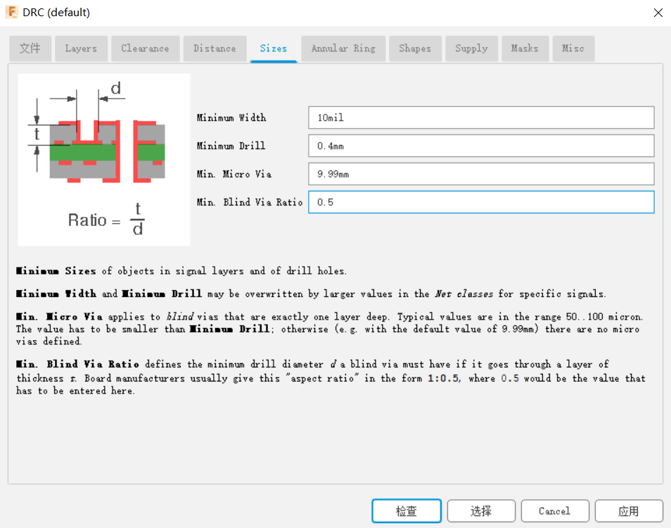
In order to do so, you also need to set the clearance and the sizes of your objects as below according to the design rules, so that they keep themselves in a safe distance.
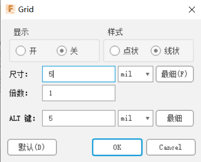
You can also change the grid to 5, so that you can adjust objects’ positions more subtly.
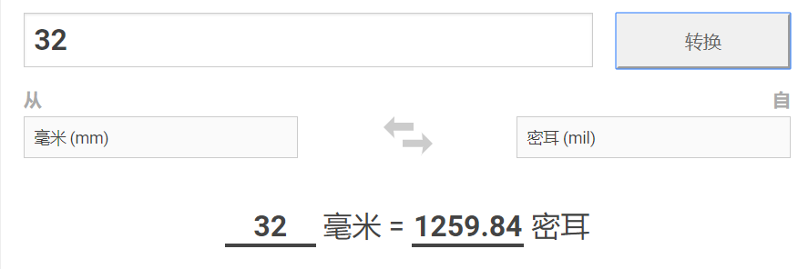
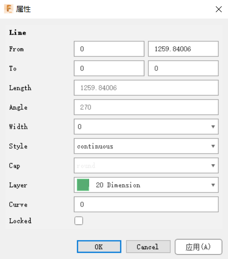
Now, after position all components properly, we can move them into the corner, and size the board to only what we need, so that we don’t waste material. We decide the length and width of the board to be both 32 mm. in Eagle we cannot just apply mm directly, we have to first convert it to mil. And we cannot drag the border directly, we right click each border and fill the dirameters. For example, if you right click the left border, and click properties, you can see many blanks. The blanks you want to fill are the top four of them. The left column represents the x axis, and the right y axis. Because the left border doesn’t change in x axis, so its distance is 0. And it’s 32 mm long, which converts to 1259.84 mil starting from 0 of its y axis.
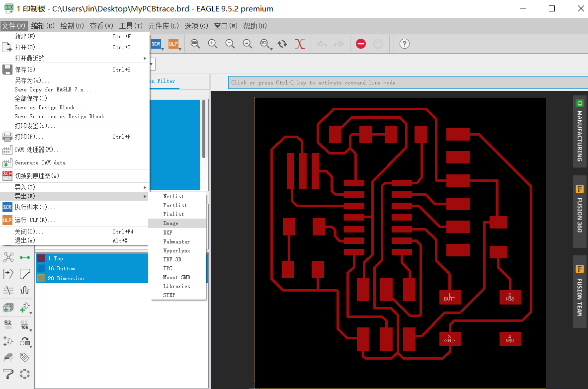
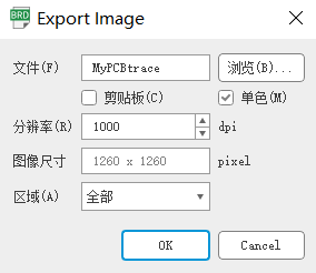
Then, you can start to export it. Since I am using fusion 360 as stated above. I have to first save the file and open it in Eagle of the separate version. Then, export the file as a png image.
Because the image of my board has a white outline surrounding it, so I have to get rid of it using PS, you can also edit your board meanwhile, like adding your name on it.
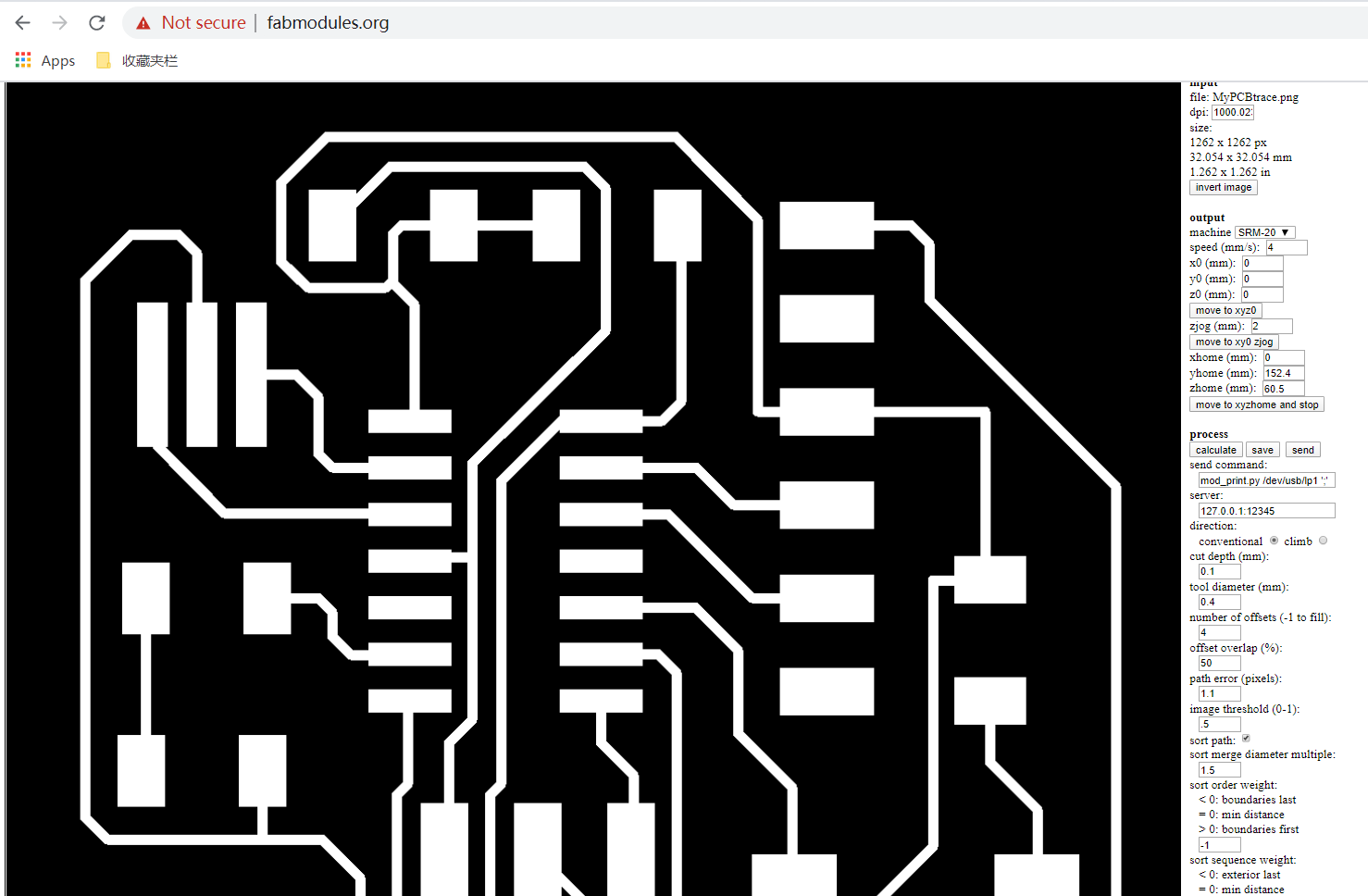
Then, open your image in fabmodules.
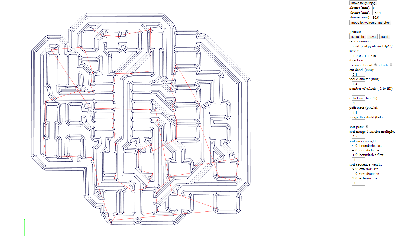
Check the lines after calculation, weather there are some missing cut. If there are, go back to Eagle, and edit the trace.
The cutting process is the same as in electronics production week.
After cutting, it's soldering. Here is the list of components I solder:
1x 6 pin header (FTDI)
1x ATtiny 44
1x Capacitor 1uF
2x Resistor 10k
1x Resistor 499
1x XTAL 20 MHz
1x 6 pin (ISP)
1x Button
1x LED (red)
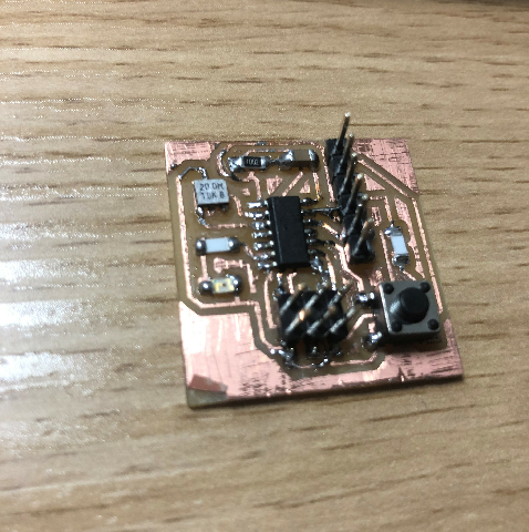
But also take a look at the beatiful board that a student in our lab made last year.
2.Program the Board
I realize that I have to download a packages of software to make the programming work, like I should have done it two weeks ago. So I follow Brian’s tutorial and download all the software I need to run it in windows.
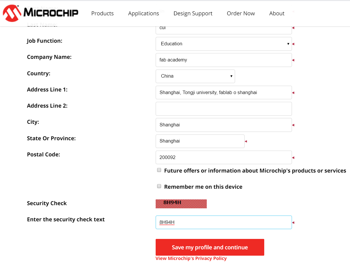
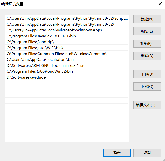
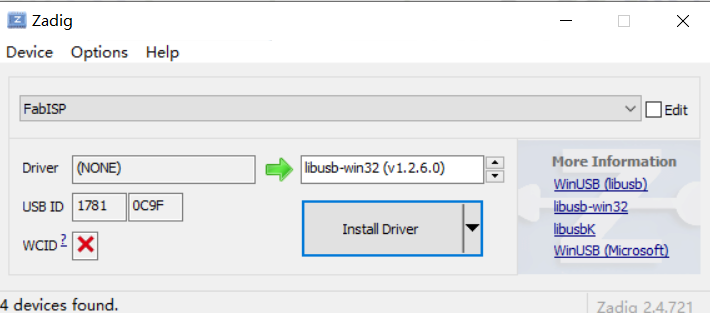
Register microchip to download toolchain, update my path for all the software downloaded, install driver.
Now, I have to download echo.c and echo.c.make to program my ATtiny44. Rename the .make file to Makefile with no extension.
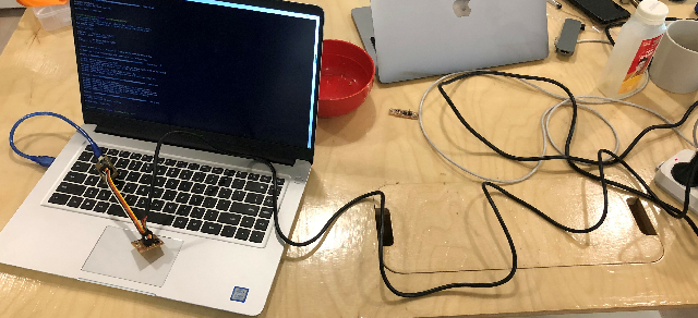
Connect your board as below. The black wire gives power to my board.
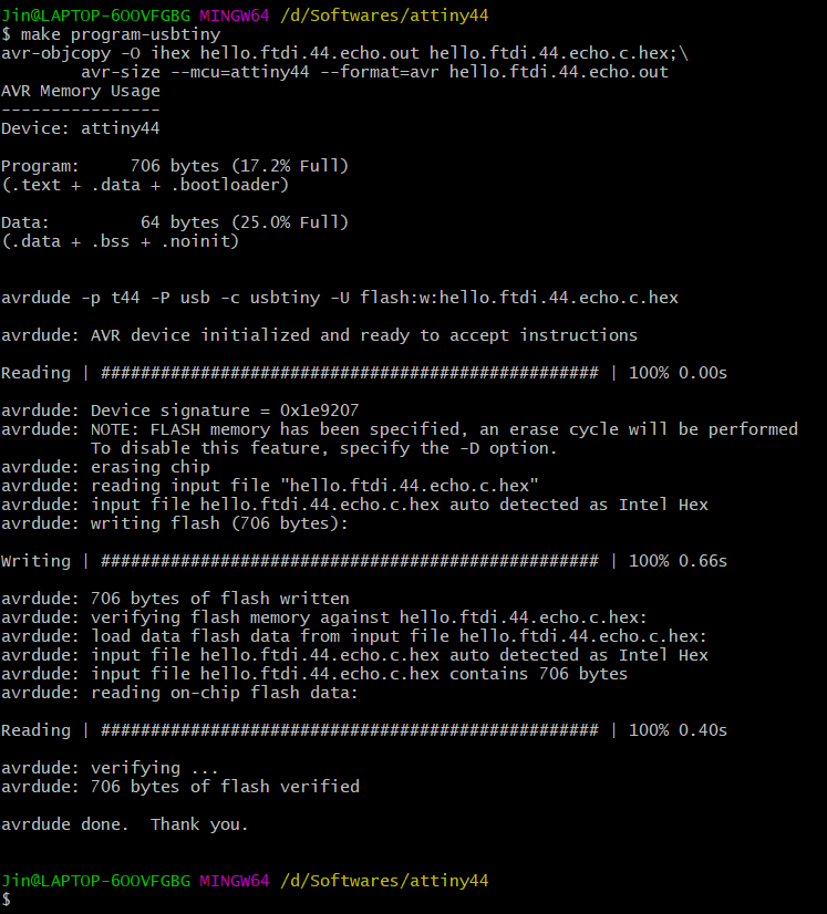
Open powershell. Go to the folder where you save your echo files. Type make. It works because I downloaded all the software I need this time. And it creates two more files.
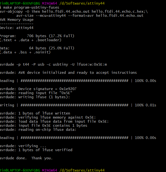
But when I type make program-usbtiny-fuses, it fails. It says that there is a connection problem.
Looking back, there are multiple mistakes that I made. There were at least three places went wrong about the traces. In two of them, the trace was cut off in the middle. I think, one of the reasons is that the PCB machine needs to cut the board in more depth. Maybe for the next time I will set the cut depth into 0.15 mm. we solder the two parts with the help of the iron that we stripped off from a resistor. There is also a place which has extra connections that it shall not have. Besides connection, I also connect the headers in the wrong sides, like the GND should face a GND when connect to each other.
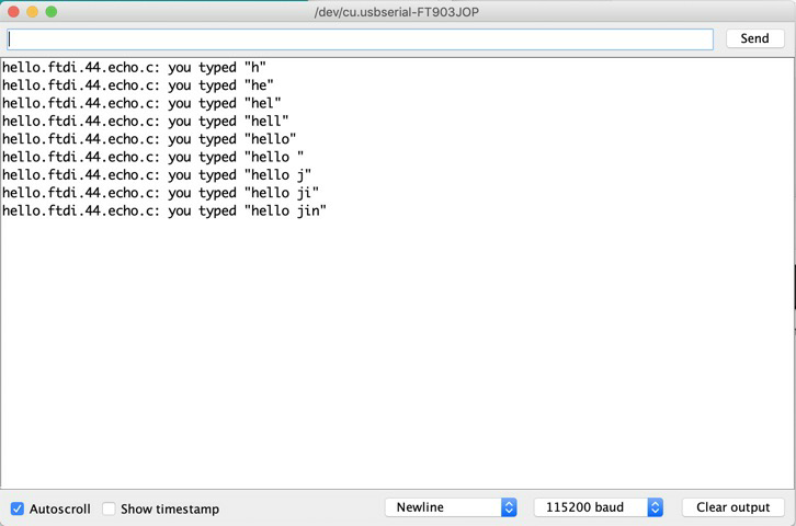
Finally, it works
3.Program it in Arduino