Exercise 8 - Embedded Programming19/3/2020 to 25/3/2020
There are 2 tasks for this week:
- Individual Assignment: Part 1: Read a microcontroller data sheet
Part 2: Program a microcontroller board to do something with as many different programming languages and programming environments as possible - Group Assignment:: Compare the performance and development workflows for other architectures
The group assignment is done with Noel Kristian and Yeo Gau Siong.
Our collective work is documented on the SP Fablab Website and hence only my learning and reflections are documented here
Individual Assignment
Part 1: Read a microcontroller data sheet
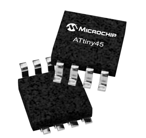 ATtiny45 microchip from Atmel
For Week 5, I built at ISP programmer and in Week 7, I built a Hello Board. For both boards, the ATtiny45 by Atmel microchip was used, hence for this week's individual assignment, I reviewed the datasheet for this microchip and also tried programming the Hello board I built in week 6.
The Full datasheet is 234 pages and it is for a S$1.63 microchip!. A 30-page summary is also available from Atmel website for quick reference. This summary document contains the main features of the chip such as the pinout diagram, architecture overview, register summary, assembly instruction set and packaging information. Being a newbie to electronics, ploughing through 234 pages of material that mostly make no sense to me is not only discouraging but required great a deal of determination. Nevertheless, I managed to pick up some characteristics and information about this ATtiny45 microchip that make some sense to me now. They are listed below:
- 8-bit microcontroller with internal 8MHz clock
- 8-pin SOIC
- 6 Programmable I/O ports (the other 2 are VCC and GND)
- Each port has its own internal pull-up resistor
- Ports are multi-functional (e.g. digital I/O, PWM, TWI
- 4K Bytes of In-System Programmable Program Memory Flash
- 256 Bytes In-System Programmable EEPROM
- 256 Bytes Internal SRAM
- 8-bit Timer/Counter with Prescaler and Two PWM Channels
- USI – Universal Serial Interface with Start Condition Detector
- 10-bit ADCs
- On-chip Analog Comparator
- Programmable configuration using Fuses
- Able to work between 2.7V and 5.5V
- Programmable Watchdog Timer with Separate On-chip Oscillator
- Speed Grade: 0 – 10 MHz @ 2.7 - 5.5V, 0 - 20 MHz @ 4.5 - 5.5V
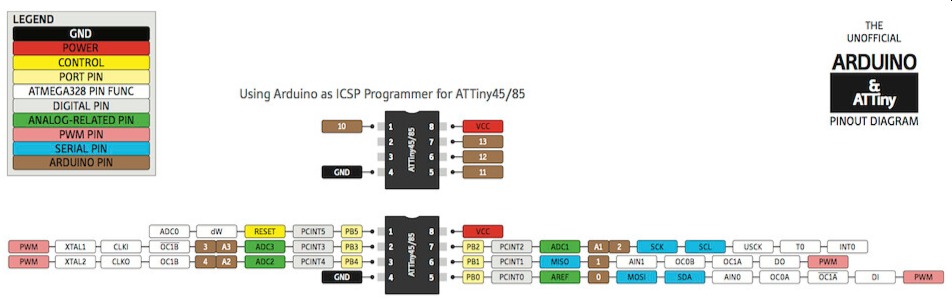 ATtiny45 Pinout from www.pighixxx.com
Apart from simply listing the specifications and peripherals available on this chip, the datasheet also lists the absolute maximum ratings where the chip will fail and special attention that one must pay when using the chip. One area is the current that the I/O port can sink. Although each I/O pin can source or sink a max of 40 mA, the maximum total current that the chip as a whole can handle (sink and source) must not exceed 60 mA.
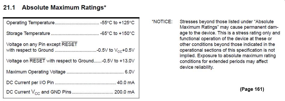
Absolute Maximum Ratings
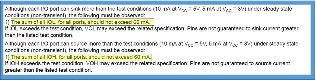
Maximum Total Allowable Current
Part 2: Program a microcontroller board with different languages and environments
(A) Programming with Arduino IDE using Sketch
I decided to start with this as I have done something similar in Week 6 when I fabricated the ATtiny45 Hello Board. In Week 6, I used ISPtiny programmer in Ardunio IDE interface to program and check that the board I fabricated work.
Ardunio IDE does not by default recognise and support the ATtiny45 chip, the ATtiny definitions must first be loaded. This step was already done 2 weeks ago (Week 6). I have included the steps here again for convenience. The first step is to load Ardunio IDE
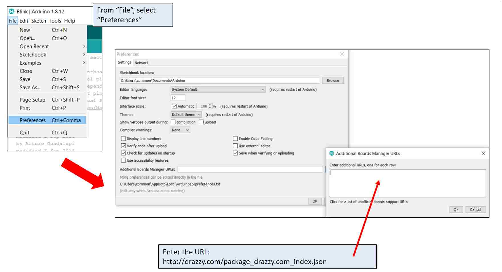
The URL (http://drazzy.com/package_drazzy.com_index.json) points to the cores that Spence Konde wrote to enable Ardunio IDE to work with ATtiny chips. Select the required Core and click install
After installation, the correct board manager needs to be specified.
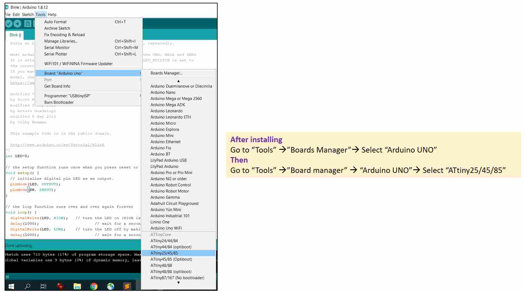
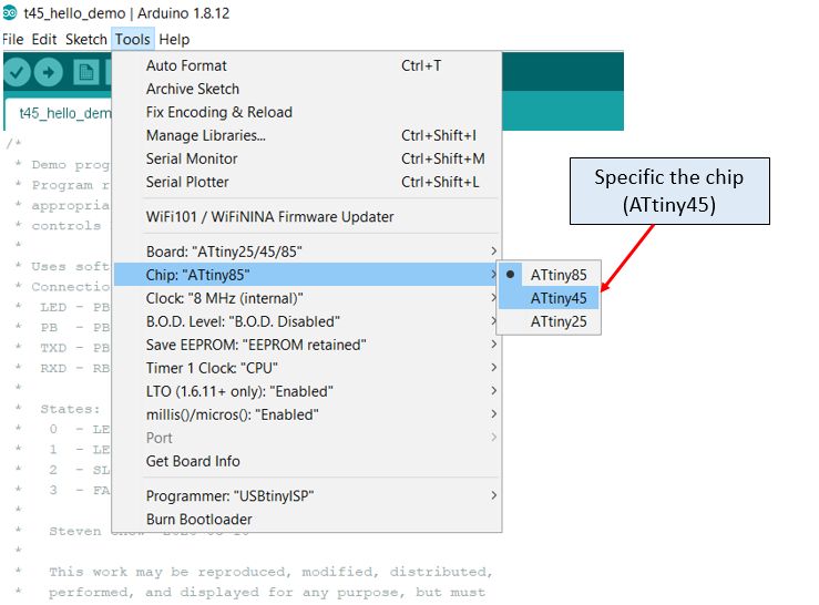
Next is to select the correct chip (ATtiny45) to complete the setup
Following that, Ardunio IDE is ready to test the program I write.
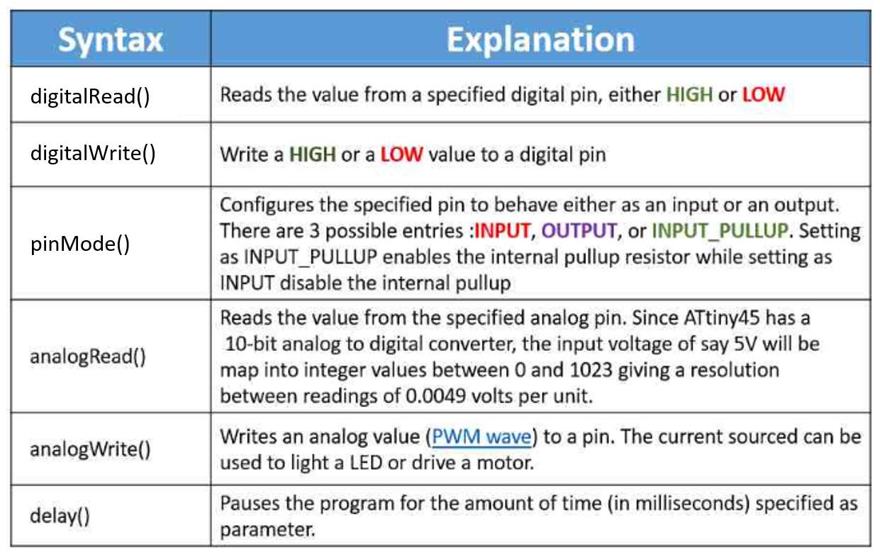
Although programming in Ardunio is said to be one of the easiest, to someone who have zero programming background like me, writing a working program is still a mammoth task. I decided to first understand the basic structure of a program wirtten in Sketch. According to Arduino Website, Sketch is the name that Arduino uses for a program. From the website, I picked up a few useful syntax
In Week 6, I uploaded the program that was written by my coach, Mr Steven Chew without much understanding. It was a modified "Blink" program. Thus for my first program, I decided to use the original Blink example that comes with Ardunio IDE, make sense out of it and edit it so that it works on my board. First is about understanding the language.
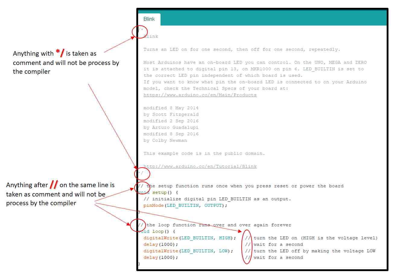
To make my board runs the Blink program, I need to modify the code, such as changing the pin definition. Before making modification, I viewed a few youtube tutorials from Sparkfun to understand the syntax as well as the control flow.
Click here to watch: Arduino Programming Syntax
Click here to watch: Arduino Control Flow
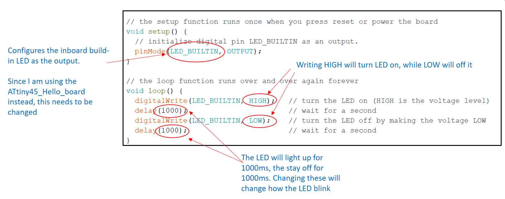
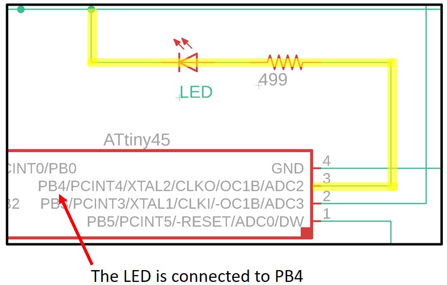
For my ATtiny45_Hello_board, the LED is connected to PB4, which is A2/4 Pin for Ardunio
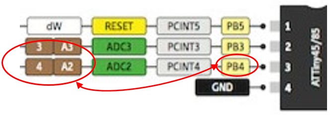 PB4_Pin4
The modifications to the code are as follows:
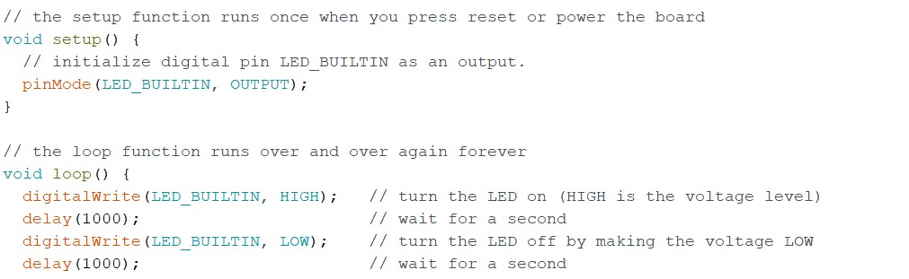 Original Code
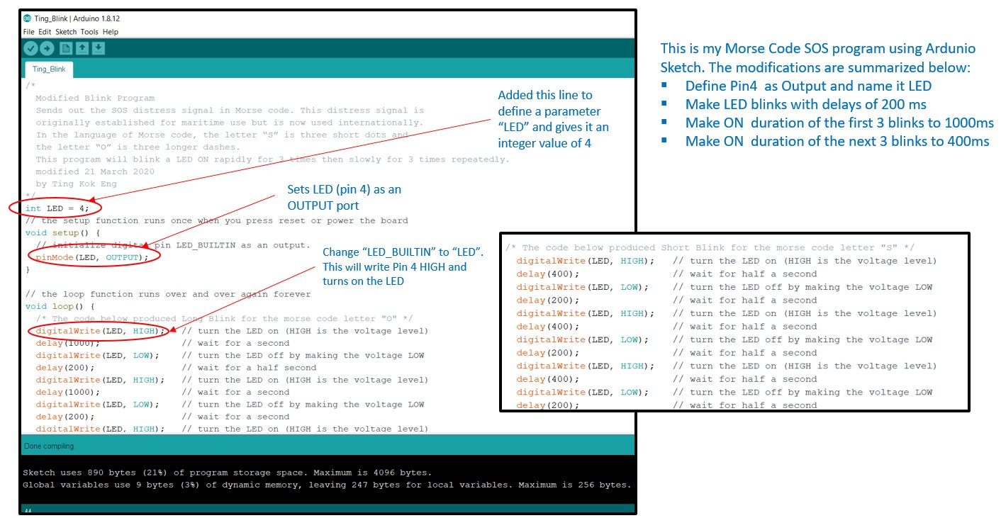 Modified Code
To test that the program works, it must be verified, compiled and uploaded. The workflow is as follows:
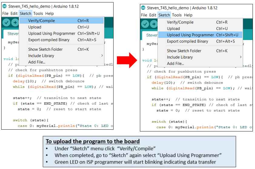
Problems Encountered
When uploading , 2 issues were encountered:
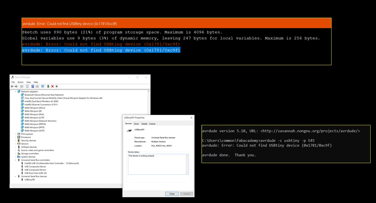 USBTiny not detected
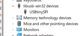
After consulting my coach, I ran Zadig.exe and changed the driver from WinUSB to LibUS and the problem is resolved. I have done this step before but did not realised that MsWindows will by default tries to load the driver that it thinks is most appropriate whenever an USB device is plugged in. The learning point is always check the driver first!
 Initialization Failed
After checking that the connections were correct, the most likely issue was the quality of the soldering. It is suspected that there could be cold solder. With no equipment on hand, I pressed the ATtiny chip vertical downwards and try uploading the program again. This time it works, confirming the issue to be due to poor soldering. I will need to fixed this when I have access to the hot air gun or soldering iron. For now, I am happy that my first program works.
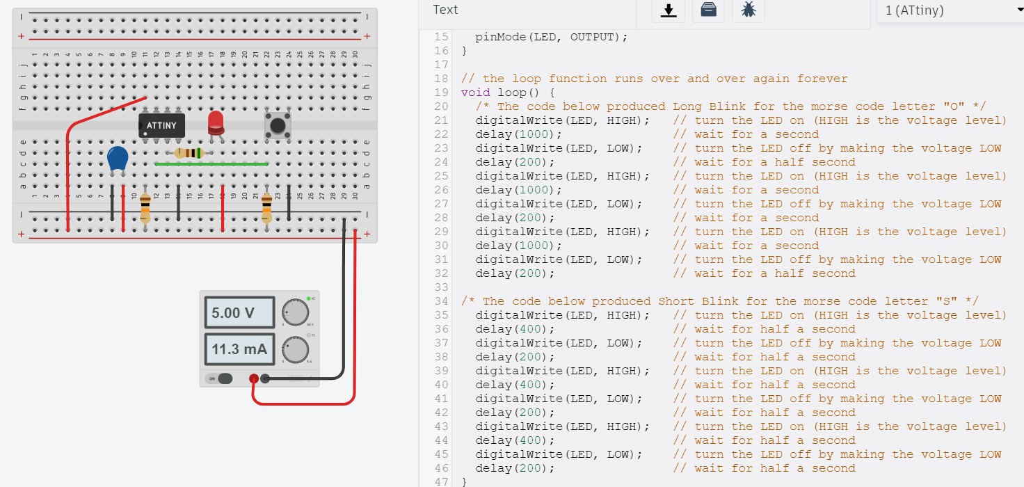
Click Here to download the Arduino file done with Sketch.As the Hello_board connectivity is questionable, the simulator TinkerCAD was tried, the Hello_board was built and the Morse code program was loaded and tested. Tinkercad is a free, easy-to-use app for 3D design, electronics, and coding created by Autodesk. It is widely used by teachers, kids, hobbyists, and designers to imagine, design, and make anything. Building a circuit in TinkerCad is extermely easy. THe user simply has to click and drag the required components or device to the workspace, link them up electrically by conecting the points together, load the code and click on simulate to test the code. The steps are summarised in the image below.
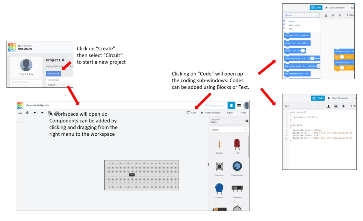
The TinkerCad simulation is as follows:
(B) Programming with C/C++ within Ardunio IDE
Having tried using Ardunio IDE and the Sketch programming language, the next way is to program the Hello_board with C/C++. The syntax is more complicated but the end result is the same and hence video of the board working is not included here. The explanations on newbiehack.com was of great help n understanding the syntax as well as about applying "mask". I have summarised my learning below:
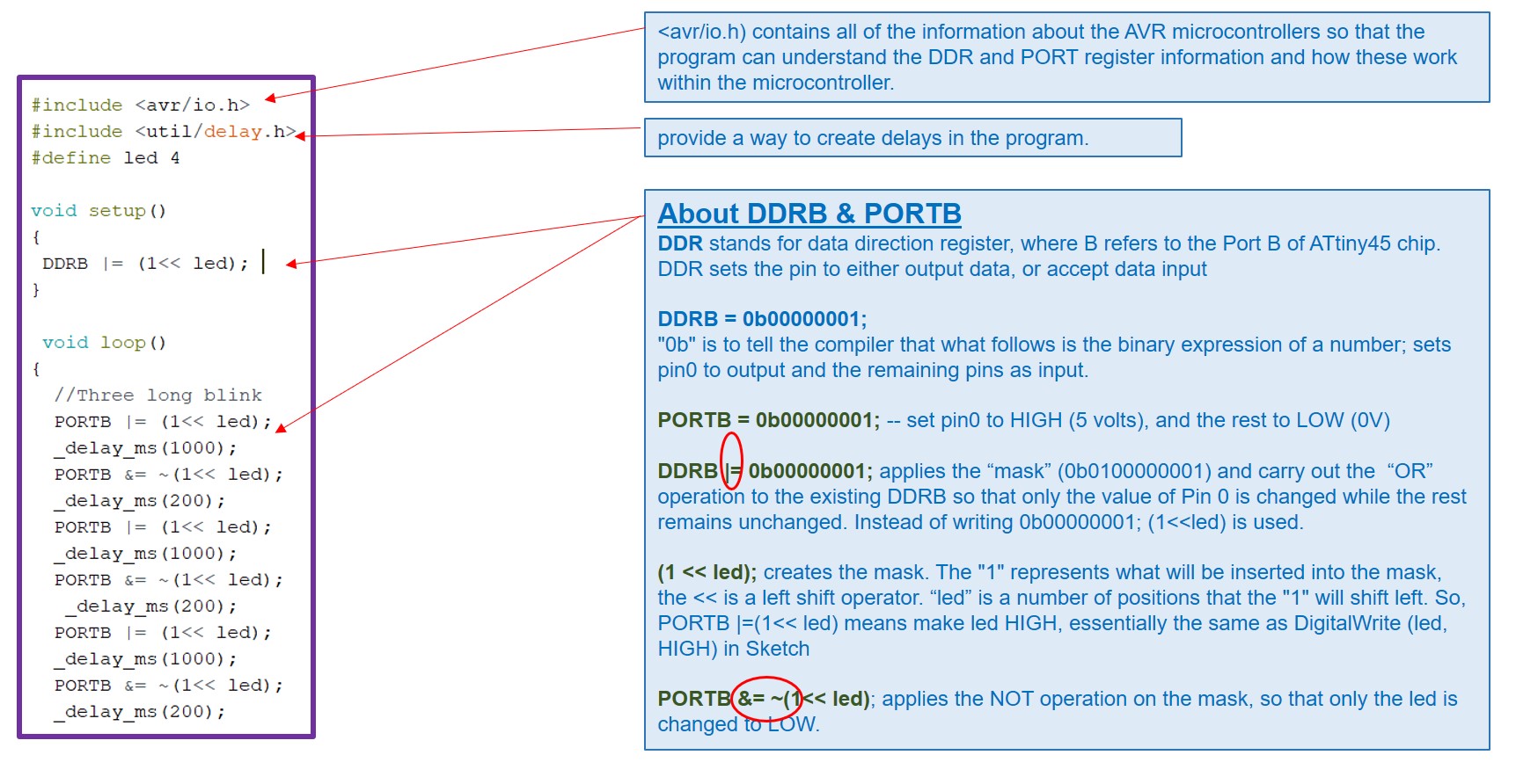
Learning C/C++
Although more complex, the program however takes up significantly less Flash memory.
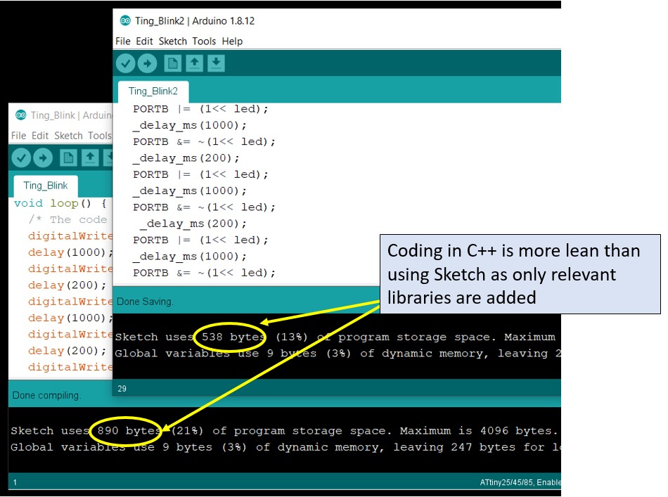 Takes up 40% lesser Flash memory
(C) Programming with Text Editor and compile with avr-gcc
For this exercise, I renamed the Ting_Blink2.ino file into morse1.c and made some minor changes to it. Saving it with a file extension of "c", turns the file into a text file that I can open in NotePad. Then I copied the file to my root directory (c:\users\common) and followed the instructions given by Casebeer in GitHub.
There are 3 steps to be carried out in command prompt environment:
- Generate the XXX.o file by typing : "avr-gcc -Wall -Os -DF_CPU=8000000 -mmcu=attiny45 -o morse1.o morse1.c
(-DF_CPU=8000000 is the speed of the microchip, I entered 8MHz.) - Generate the XXX.hex file by typing : "avr-objcopy -j .text -j .data -O ihex morse1.o morse1.hex
- Upload the program to the target board by typing : "avrdude -c usbtiny -p t45 -U flash:w:morse1.hex:i
Basically what these 3 steps do is to compile the C++ program file into machine readable Hex file. The first step is to create the object file (morse1.o). The morse1.o is a binary of the application. As most, if not all, programmers will not accept a GNU executable as an input file, further processing is required. The second step extracts portions of the binary and save the information into .hex files. The GNU utility that does this is called avr-objcopy. The third step then simply upload the program to the target chip. The frist 2 steps can actually be placed in a make file, so that repeated typing of the commnads can be avoided.
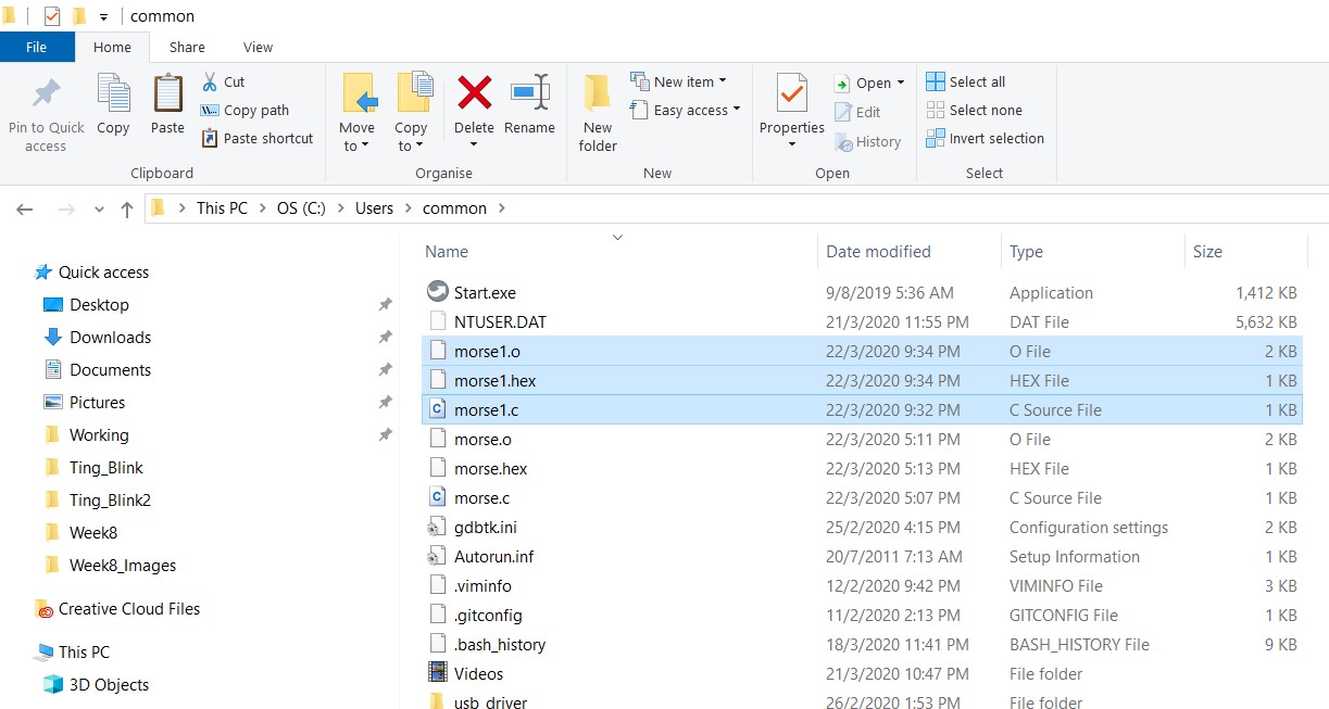
o & Hex files created
The uploading is successfully completed. Using this method, the flash memory used is even lower at 276 bytes!
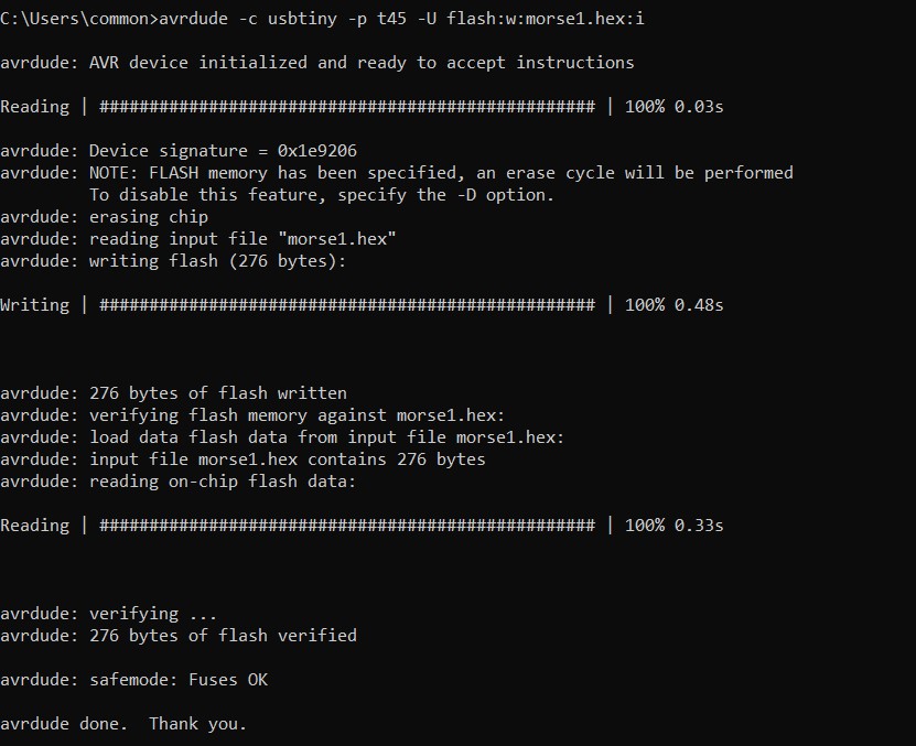
Successfully Uploaded he file
Click Here to download morse1.o file
Click Here to download morse1.hex file
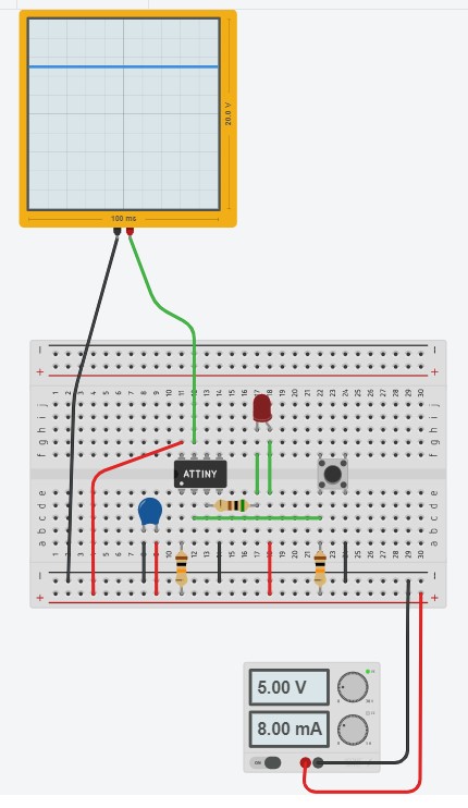
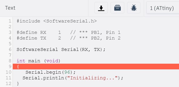
(D) Use TinkerCAD to understand Serial I/O
Finally, I tried is to simulate a serial output. I connect a oscilloscope to the TX pin (PB1) and GND. Then I ran a very short program and observe the way form.