Exercise 17 - Mechanical Design & Machine Building28/5/2020 to 3/6/2020
This is a group assignment, in the past, it was split into 2 weeks; Mechanical Design one week and Machine Building another. For this cohort, these 2 assignments are combined. The requirements are:
- Design a machine that includes mechanism + actuation + automation
- Build the mechanical parts and operate it manually.
- Actuate and automate the machine.
- Document the group project.
As this is a group project and we are expected to each take charge of a part of the project. For the Individual assignment, we are to document our individual contribution.
⛏What machine should we make?🔧

In view of Covid-19 situation, we decided to make a non-contact sanitizer dispenser with automatic bottle changing capability. The details about the design is documented on our Group Assignment page.
We divided the project into several subtasks with each of us taking charge of an area. The job division is as follows:
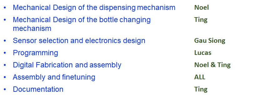
📐What I am in charge off - Bottle changing mechanism🛠
We have set the number of times of sanitizer dispensing as at least 800 times before any human intervention, this means a volume of about 800ml of sanitizer is required. Most bottled sanitizers are aroun 250ml to 500ml in volume, hence a bottle changing mechanism is required.
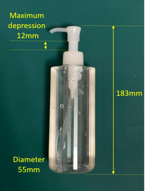
For this project, we use the following bottle for our design. This bottle has a volume of 300ml and the volume of each squirt is about 1ml. Hence, the design must be able to hold 3 of these bottles
I explored 2 ways of changing the bottles which both requires only a stepper motor. The rough sketches are as below:
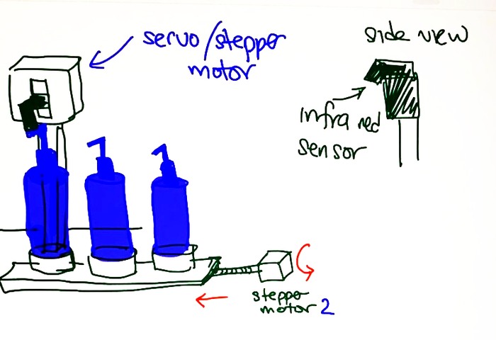 Design 1
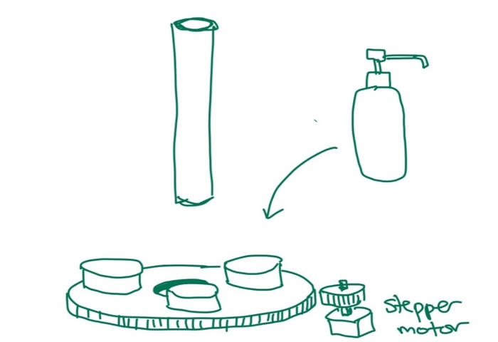
Design 2
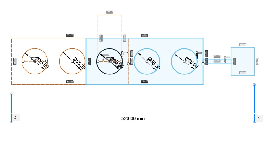
For Design 1, the bottles can be changed using a pinion and rack mechanism or a linear stepper motor with lead screw. However this would mean that the design would have a length of more than 500mm! (3 bottles each with diameter 55mm plus the stepper motor and housing). One of our design requirement is compact and small, hence I decided to drop this idea and explore Design 2
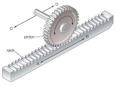
Pinion and Rack
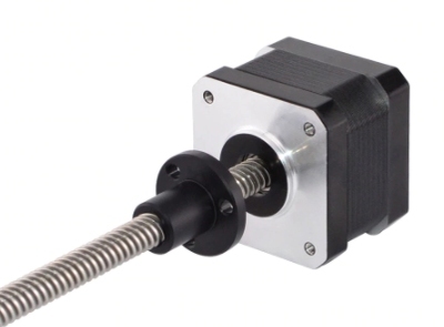
Linear Stepper
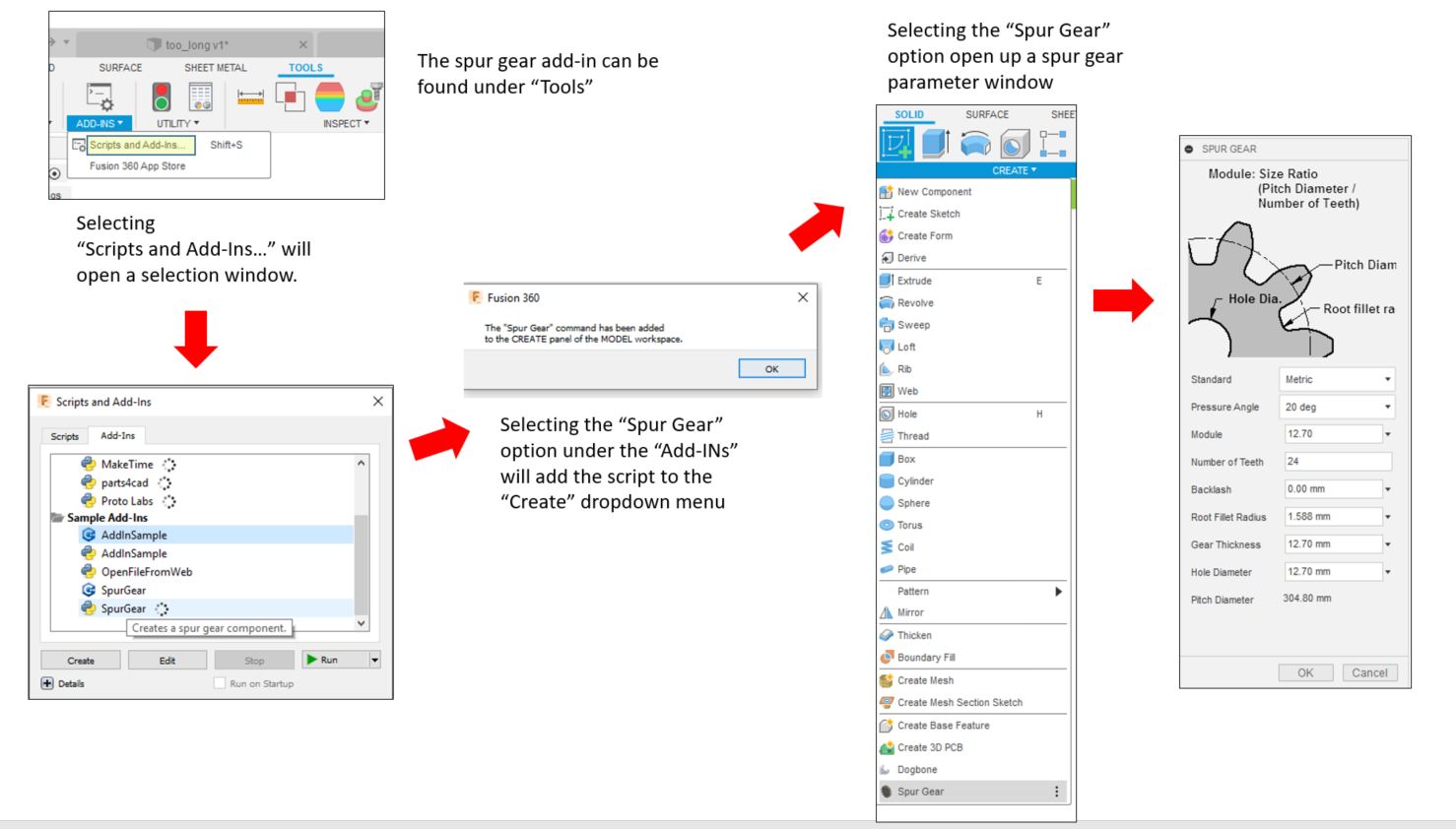
For Design 2, I plan to use spur gears. Fusion 360 as an Add-in that can make generating the spur gears a breeze. The spur gear can be found under the "Tools". There are two Add-in scripts for Spur gear, one written in C++ and the other in Python. I tried both, there is no different in the graphic interface and all the input fields are identifcal. The difference is only in the background scripting which is transparent to the user. I decided to use the Python script following the recommendation in Kevin Kennedy's tutorial videos although I do not really know why at is moment. The instuctions to do so are summarised in the image below. A Spur Gear option is added to the Create dropdown menu which makes adding spur gears much more convenient.
To design the spur gears properly I followed the tutorial video by Kevin Kennedy closely. In the video however, Mr Kennedy explained briefly the meanings of the various input field. In order to have a better understanding of these parameters, I did some reading up about anatomy of a gear as well as the design guidelines for gear design My learning is summarized below. One of the website I referred to is khkgears.net.
Pressure Angle
This is the angle in relation to the gear key. With limited knowledge in this area, I decided to use 20 degree which is the most common pressure angle for spur gear.
Module
Module is defined by the quotient of the number of teeth to the pitch diamater. The pitch diameter is the diameter used for spacing the gear. For this spur gear Add-IN, the pitch diameter is a dependent variable determined by the number of teeth and the module.
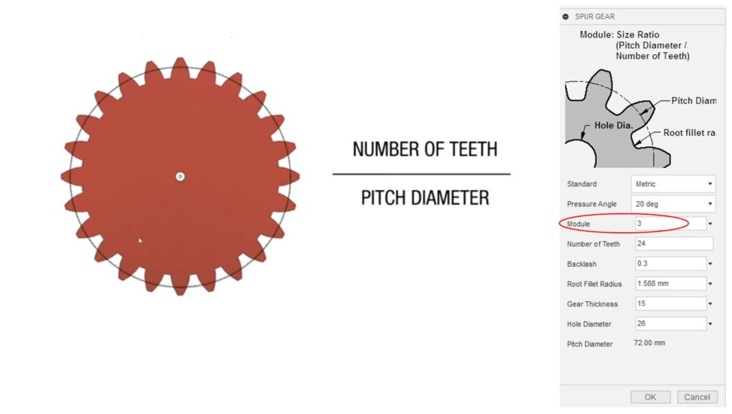
Image from Rob Durate youtube video
Backlash
This is the tolerance between the teeth of one gear to the gear.
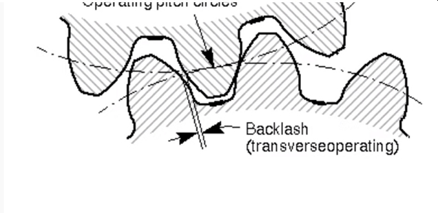
Image from Rob Durate youtube video
Root Fillet Radius
This is radius where the teeth meet the root or the base of the teeth. A large root fillet radius would make the teeth stronger but if too large, the teeths of the second gear to would not fit into the first gear.
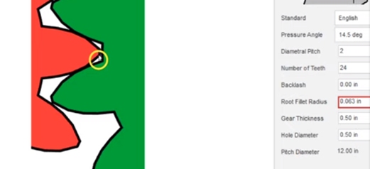
Image from Rob Durate youtube video
I followed the instructions from Kevin Kennedy's and successfully designed the bottle changing mechanism. The design is as follows:
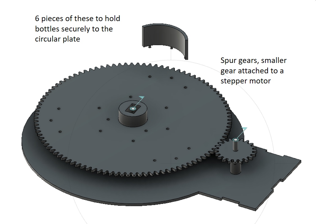
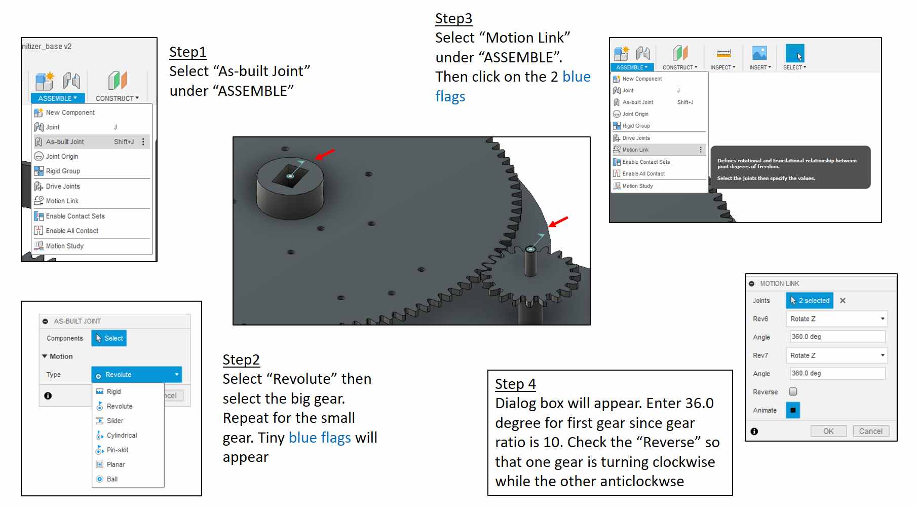
To make sure that the spur gears are properly designed and position, I used the animation function in Fusion 360. There are several steps to achieved and they are summarised in the image below for easy referring.
The short video clip shows that the spur gears can turn properly
The Fusion 360 file can be downloaded from autodesk360.com below (*.f3d file is not attached here as it is 11.3mb)
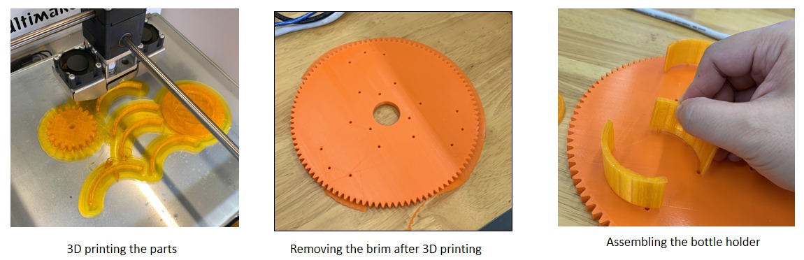
Fabricating the parts
All the parts are fabricated using 3D printing and assembled.
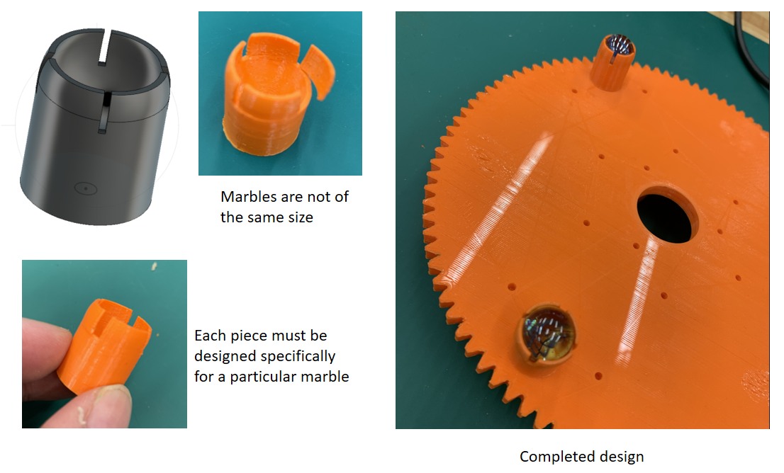
To make the revolving mechanism smoother, 3 support pins with rolling balls were designed. I was however unable to get hold of metal balls and decided to use marbles instead. This however caused problem as the marble sizes actually vary quite widely to my surpise and I have to customise the design for each marble
Click Here to download the all the stl files using for the 3D printing as a zip file.
With the pressing mechanism (design and fabricated by Noel Kristian) assembled, the machine can work properly mechanically by hand. The next phase is to pass the setup to Yeo Gau Siong and Lucas Lim to work on the servo and stepper motors.
The short video clip shows the mechanical movement of the setup by hand
The project is completed (with the program loaded) is shown in the video below:
After dispensing 3 times (to simulate last few presses), the turntable will turn to change to a new bottle.
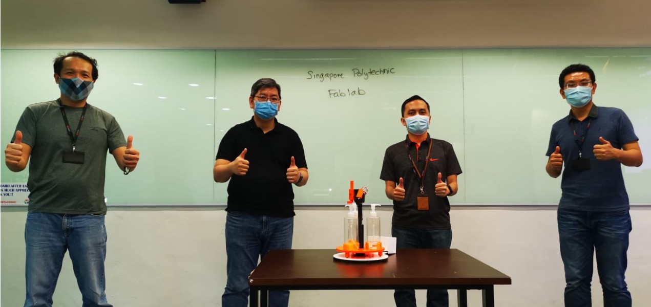 The Team