Exercise, Week 04 - Electronics Production
Group Assignment
This
is a group assignment done with Ting
Kok Eng and Noel
Kristian.
Our collective work is documented on the SP Fablab Website Assignment 2 and
hence only my learning and reflections are documented here
What I have learned:
1. Secure the PCB board firmly onto MDF board using double-sided tape before milling.
2. Reduce feedrate to slow speed when using long shank cutting bits, is will prevent bits from breaking.
3. Use MODS to convert the raster images to gcode files before using CNC machine.
Building my AVR ISP programmer
In week 4, I will be making an in-circuit programmer by
1. Generate G Code files using the PNG files for PCB traces and PCB outline (PNG files reference from Building the FabTinyISP by Brian)
2. PCB milling with STEPCRAFT 420
3. Assembling the milled PCB with electronic components and a microcontroller
4. Setting up and test it.
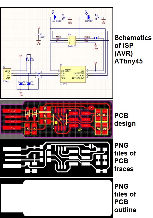
Download the PNG files for PCB traces and PCB outline (1)
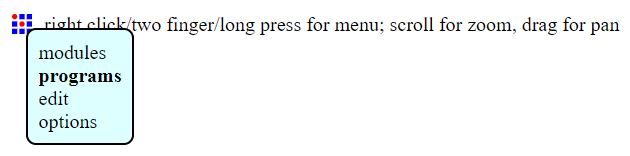
Load MODS programs (2)
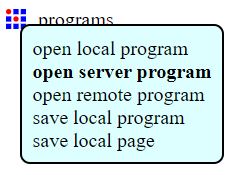
Select open server program
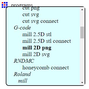
Select G-code > mill 2D png
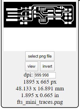
Select png file
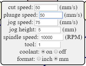
Setting for speed
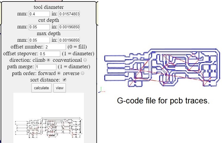
Setting for tool diameter. Select calculate and save the G-code file for pcb traces.
PCB milling with STEPCRAFT 420
STEPCRAFT 420 is a CNC machines from Germany, it will perform a subtractive manufacturing process using computerized controls and machine tools to remove layers of material from a stock piece and produces a custom-designed part.
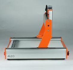
I will use a STEPCRAFT420 (1) to mill my PCB (3).
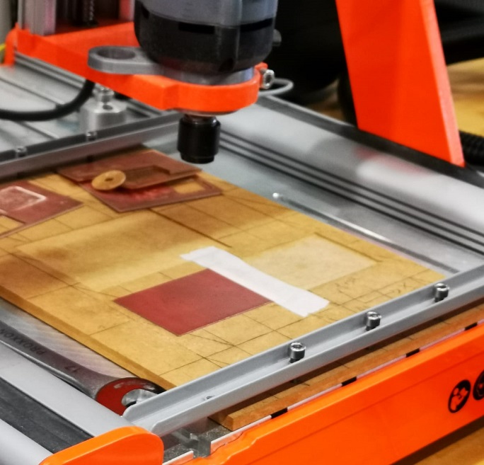
I will use a STEPCRAFT420 (1) to mill my PCB (3).
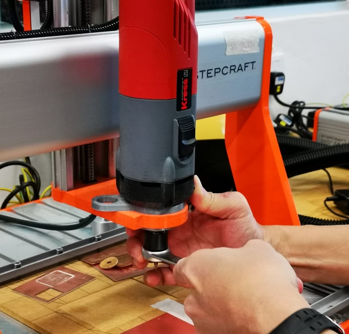
Setting up end mill 0.4mm for cutting PCB trace, and last cut for PCB outline use 0.8mm.
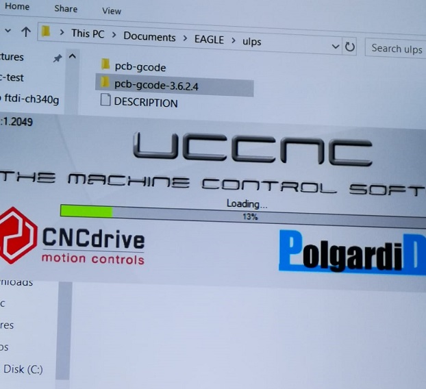
Load UCCNC program.
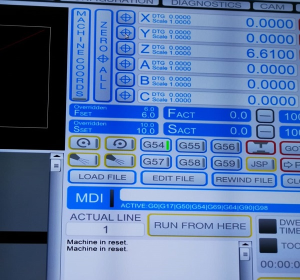
Load G-code for PCB trace.
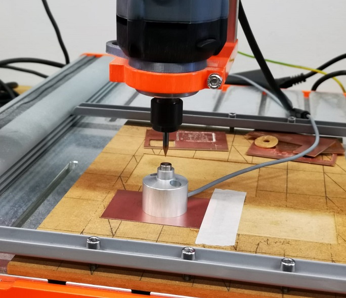
Set X, Y and Y origin.
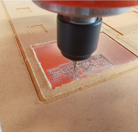
Select Start Cycle. CNC machine start cutting.
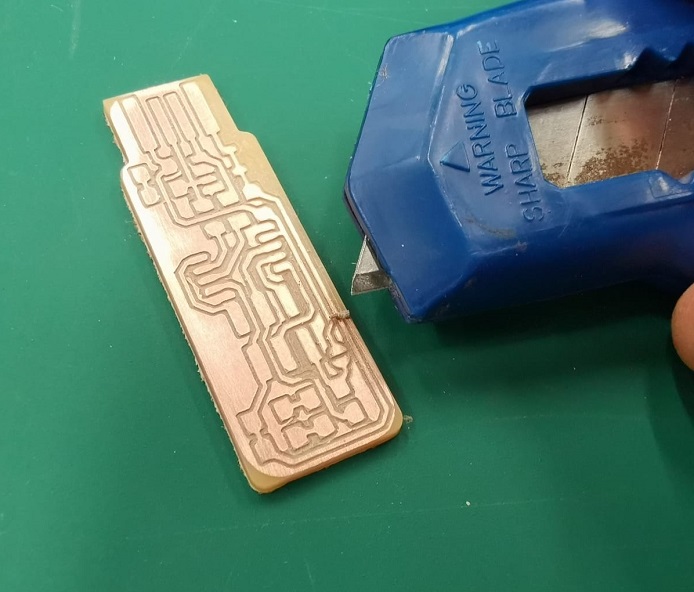
Completed CNC on an AVR ISP programmer PCB and remove dead copper.
Assembling the milled PCB with electronic components and a microcontroller
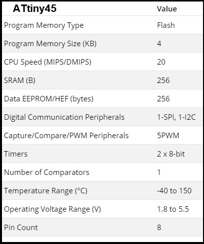
Parametric of ATtiny 45 (4)
Parametric of ATtiny 45 (4) The microcontroller on in-circuit programmer is a ATtiny 45; this is a high-performance, low-power Microchip 8-bit AVR RISC-based microcontroller.
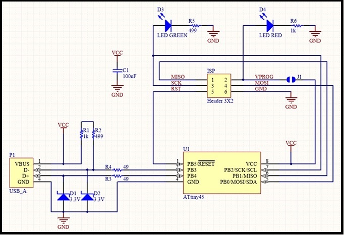
AVR ISP programmer using ATtiny 45
Components for AVR ISP programmer
o 1x ATtiny45 or ATtiny85
o 2x 1kΩ resistors
o 2x 499Ω resistors
o 2x 49Ω resistors
o 2x 3.3v zener diodes
o 1x red LED
o 1x green LED
o 1x 100nF capacitor
o 1x 2x3 pin header
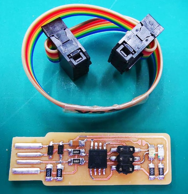
Assembled all components on the PCB for AVR ISP programmer and made an IDE cable for header connections.
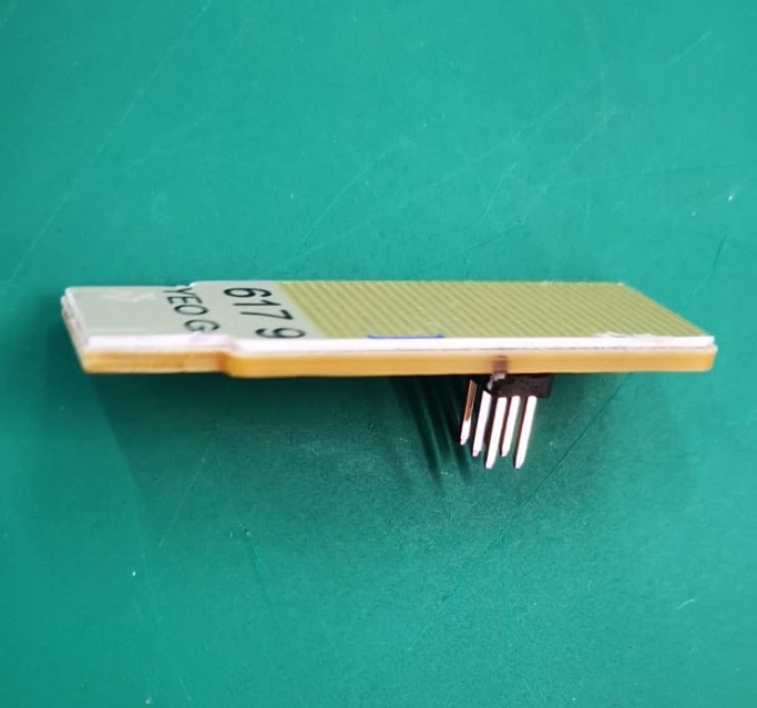
Created a backing for on the AVR ISP programmer, 0.8 mm thickness is added.
Setting up and test the new AVR ISP programmer
I need a working AVR programmer to initialize my new board, before my board becomes a AVR ISP programmer. This AVR ISP programmer is a FabTinyISP, it is a "low-speed" USB 1.1 device, operate at 1.5 MHz and have much less strict timing requirements, which enables a purely software-based implementation of the USB protocol to be used (the ATtiny45 does not have hardware USB capability), therefore, I will use it on USB 2 only (1).
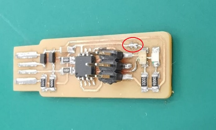
Solder a bridge ISP header (J1). This connects VCC to the Vprog pin on the ISP header so that the header can be used to program the tiny45. Remove this bridge to turn the board into the programmer when its target board have its own VCC.
Setting up - Software Installation
Using windows, I installed the following software (5).
o Atmel GNU Toolchain (6)
o GNU Make (7)
o avrdude (8)
And, perform a update of my PATH for these installed in Windows; Advanced System Settings > Environment Variables.
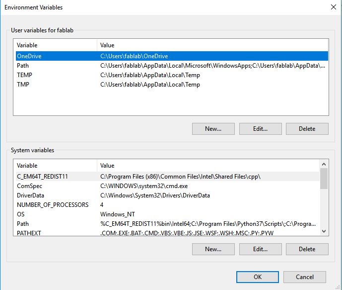
The three values are:
o C:\Program Files\avr8-gnu-toolchain\bin
o C:\Program Files (x86)\GnuWin32\bin
o C:\Program Files\avrdude
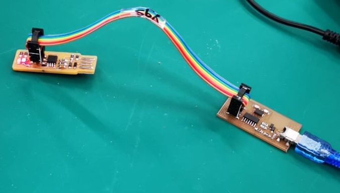
Plug the working AVR programmer into a USB 2.0 port, with the programmer ISP header connect to the ISP header on my board using the IDE cable (get pin 1 in the right place, it has the MISO signal connected to it) and the red LED lit up.
Next, download and extract the following zip file from this firmware source code, than run make in command prompt with cd into the source code directory. This will build the hex file that will get programmed onto the ATtiny45. After command is completes, a file called fts_firmware.hex will be generated. If something is wrong, check toolchain installation.
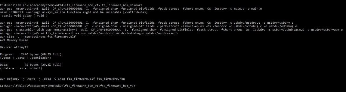
Note: By default, my Makefile use the programmer in the usbtiny family, for windows user can use Notepad++ to update the Makefile for the type of programmer they are using to program their programmer board (1).
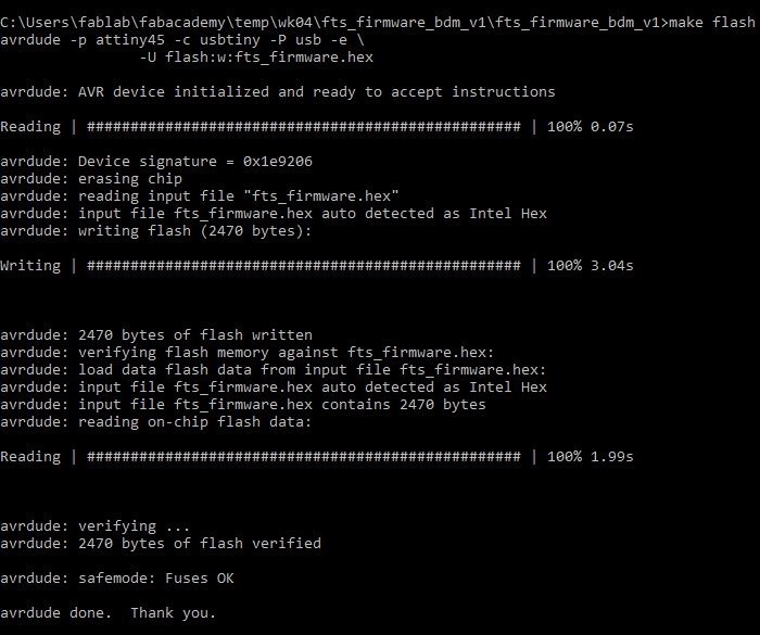
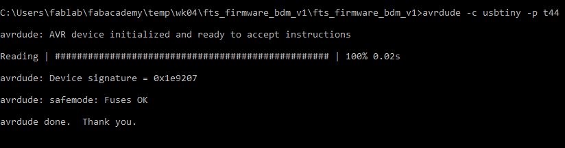
Run make flash, this command will erase the target chip, and program the flash memory with the contents of the .hex file built. You should see several progress bars while avrdude erases, programs, and verifies the chip.
After programmed the flash memory, the next thing is to set the configuration fuses. First, set the fuses that control where the microcontroller gets its clock source from, because the board works as a USB device and it requires the clock to come from the PLL.
Confirmed that USB works, set the fuse that disables the reset pin and turns it into a regular GPIO pin, i.e. letting the chip use the reset pin to program other boards, but will disable the ability for this chip to be programmed. Run the make fuses command. This will set up all of the fuses except the one that disables the reset pin.

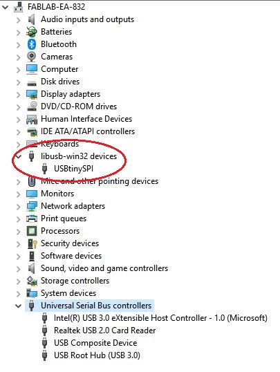
Check the USB Functionality
Check to make sure that the USB on your board works, before blowing the fuse that will enable it as a programmer. Unplug all connections and only insert my USB board to the USB 2.0 port on my computer. In windows Device Manager, the USB devices will appear as USBtinySPI device.
Blow the Reset Fuse
The two final steps left to turn my board into a AVR ISP programmer, i.e. it can program other boards.
First, change the bit that will turn the ATtiny45's reset pin into a GPIO pin, this will disable the ability for this chip to be programmed. When everything is working, connect the working AVR programmer to my board for the last time and run make rstdisbl. This is similar to make fuses command, and include that reset disable bit. After executing, avrdude will never be able to talk to this chip again through the ISP header.
Finally, testing my AVR ISP programmer
Now a working AVR ISP programmer, used it to program a target board and it work successfully.
Citation
(1) reference from URL on 230220: http://fab.cba.mit.edu/classes/863.16/doc/projects/ftsmin/index.html
(2) reference from URL on 230220: http://mods.cba.mit.edu/
(3) reference from URL on 230220: https://shop.stepcraft-systems.com/media/image/product/8/md/stepcraft-2-420-ready-to-run-system.jpg
(4) reference from URL on 230220: https://www.microchip.com/wwwproducts/en/ATtiny45
(5) reference from URL on 230220: http://fab.cba.mit.edu/classes/863.16/doc/projects/ftsmin/windows_avr.html
(6) reference from URL on 230220: https://www.microchip.com/mplab/avr-support/avr-and-arm-toolchains-c-compilers
(7) reference from URL on 230220: http://fab.cba.mit.edu/classes/863.16/doc/projects/ftsmin/make-3.81.exe
(8) reference from URL on 230220: http://fab.cba.mit.edu/classes/863.16/doc/projects/ftsmin/avrdude-win-64bit.zip
(9) reference from URL on 230220: http://fab.cba.mit.edu/classes/863.16/doc/projects/ftsmin/fts_firmware_bdm_v1.zip