Exercise, Week 15 - Molding and Casting
Group Assignment
Review the safety data sheets for each of our molding and casting materials. Make and compare
test casts with each of them.
This is a group assignment done with Ting Kok Eng, Noel Kristian and Lucas Lim.
Our collective work is documented on the SP Fablab Website Assignment 11 and hence only
my learning and reflections are documented here.
Individual Assignment
This is week topic is on design a 3D mold (positive mold) around the stock (i.e. blue form),
using a STEPCRAFT 420 a 3 axis CNC machine to mill out my positive mold. Then, I will make
a negative mold by casting the positive mold with silicone. With this silicon mold created
I can cast model pyramid repeatedly.
Creating a Mold Design Using Fusion 360
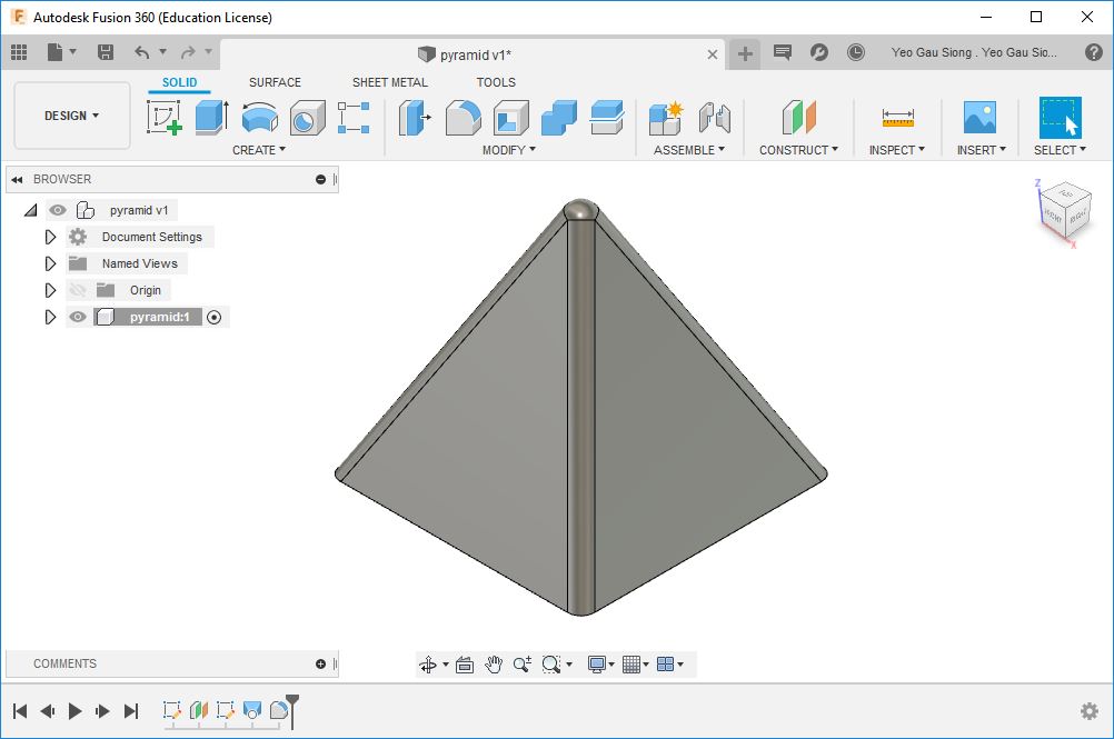
I had created a pyramid using Fusion 360; base is 30mm by 30mm, and height is 30mm.
The stock I am using is 50mm thickness. The height different between my mold and
pyramid is 10mm, and the base of my stock is also 10mm for my pyramid to sit on.
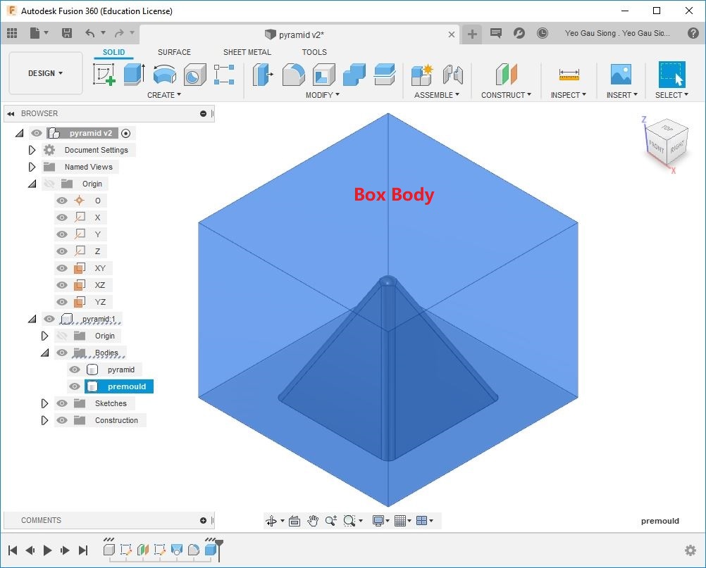
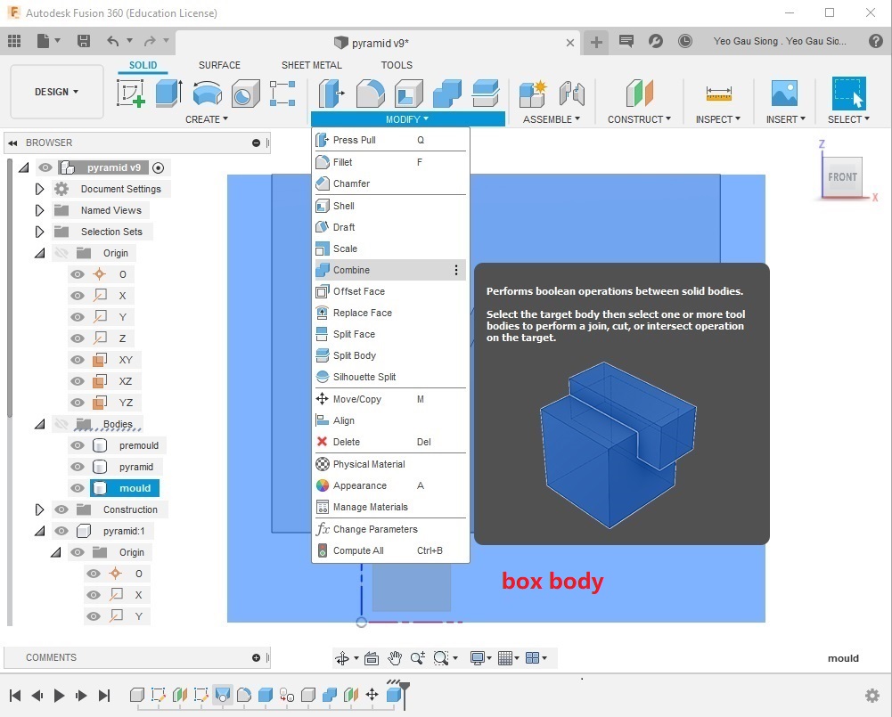
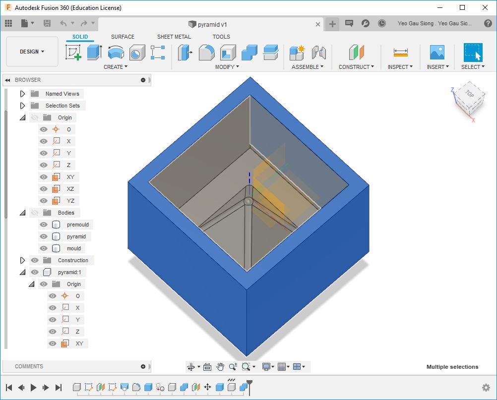
Created a box body from XY plane to contain the pyramid. Box body base is 50mm by 50 mm, height is 40mm.
Next, using the combine feature to subtract objects one from another, this help me to created a tool body in Fusion 360 for making my pyramid mold.
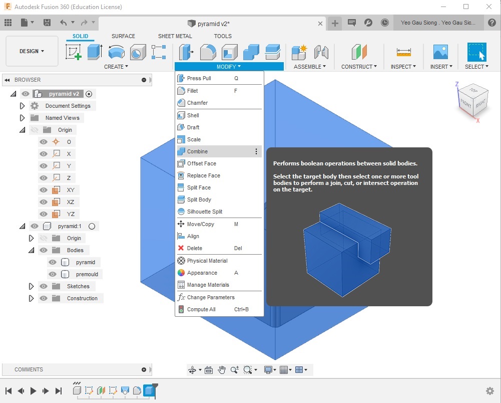
Using the combine feature to subtract pyramid body from a box body.
Select Modify>Combine
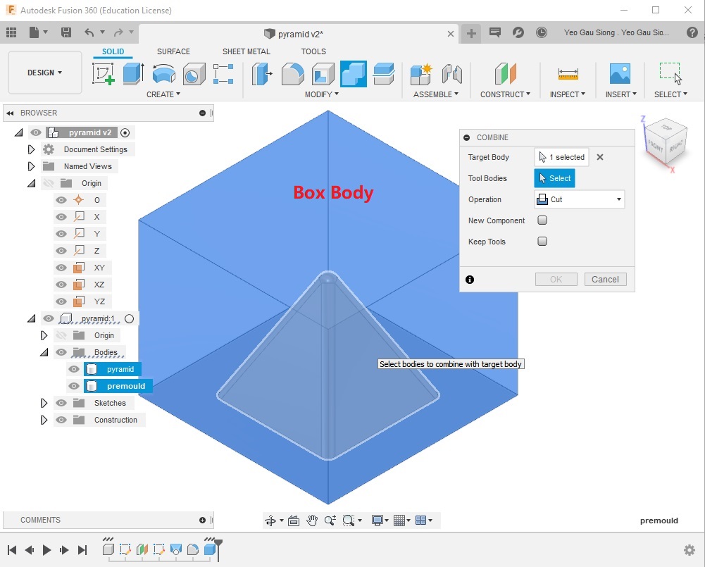
Select Target Body, this is the created box body.
Select Tool Bodies, this is the pyramid to cut away from the box body.
Select Operation>Cut, this allow the tool body (i.e. the pyramid) to be cut out the
material from my box body.
Select New Component and keep Tools.
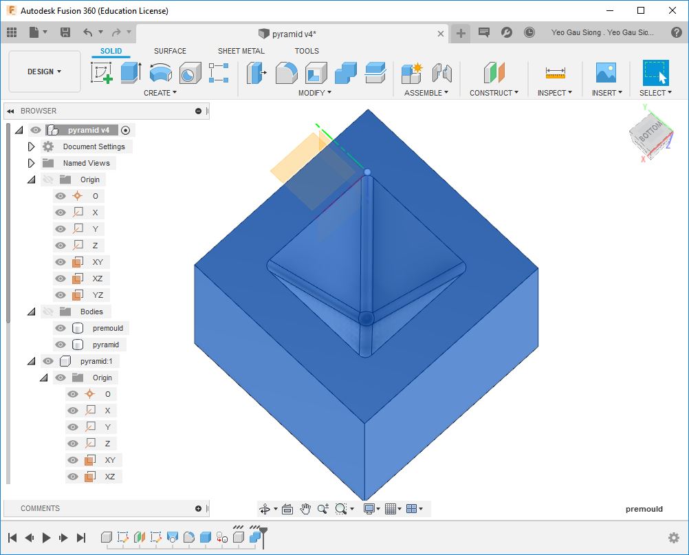
Created my tool body, this is the bottom view of my pyramid tool body. Combine feature had subtracted my pyramid from the box body.
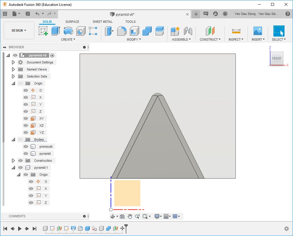
Next, my tool body is moved up by 10mm. This will allow tool body to sit on the base of my new box body (i.e. the stock) by 10mm.
Next, creating my pyramid mold from the previously created tool body in Fusion 360. Again, I use combine feature to subtract my tool body from a created box body (i.e. the stock base is 60 by 60, height is 50mm).
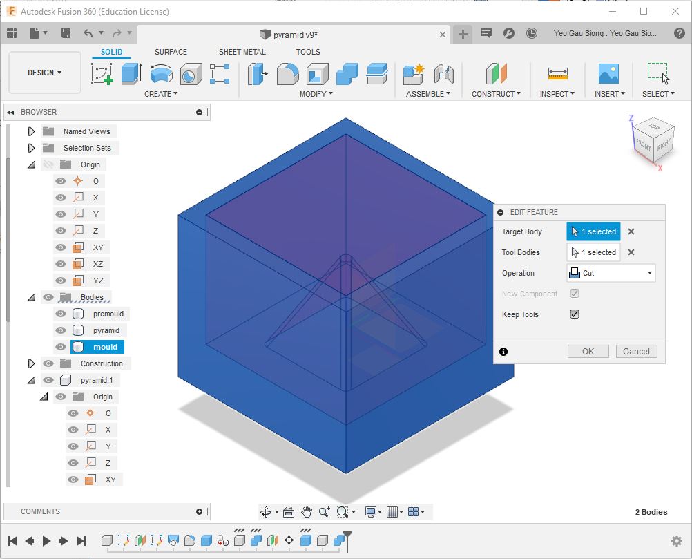
Using the combine feature to subtract tool body from a box body.
Select Modify>Combine
Select Target Body, this is the box body created for the mold.
Select Tool Bodies to cut away from the box body.
Select Operation>Cut, this allow the tool body to cut out the material from the box body.
Select New Component and keep Tools.
Created a design of a 3D one-part mold, the stock base is 60 by 60, height is 50mm.
After simulating milling process with my design, I discovered there are milling collision if I use a
STEPCRAFT 420 with a 3mm end mill. So I decided to resize my design of 3D one-part mold.

To scale down my design. Select Modify>Scale
I had resized the length and width to 30 by 30mm, and height to 16mm.
Finally, I had created a design of a 3D one-part mold.
Next is to generate the toolpath and G-code from my mold before sending my stock for cutting my pyramid mold.
Generate Toolpath and G-code
A good tutorial on how to create toolpaths and g-codes: Making TOOLPATHS and exporting G-CODES | Fusion 360 | Quick Tip
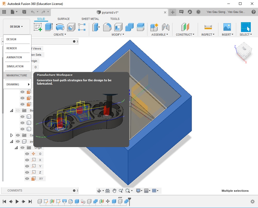
Creating toolpaths for my mold design. Select DESIGN>MANUFACTURE
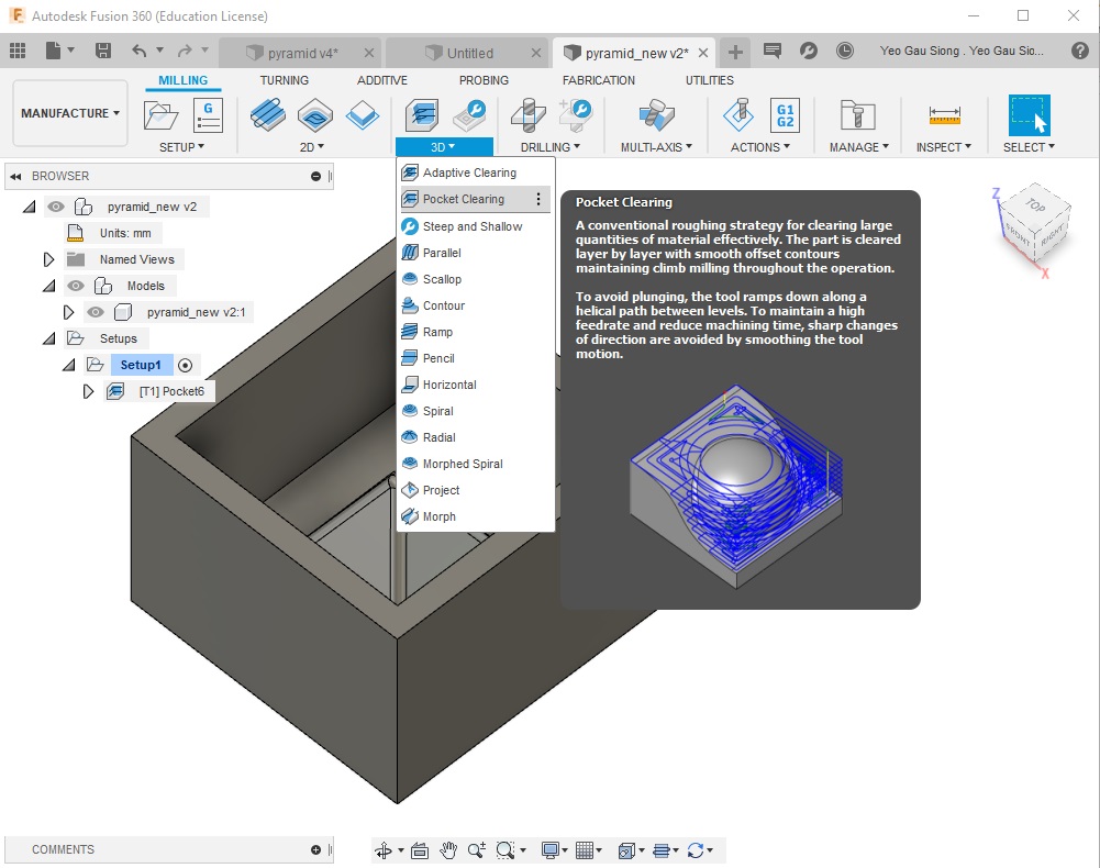
I had chosen pocket clearing for my toolpaths, this will allow milling to clear large quantities
of material effectively. Select 3D>Pocket Clearing
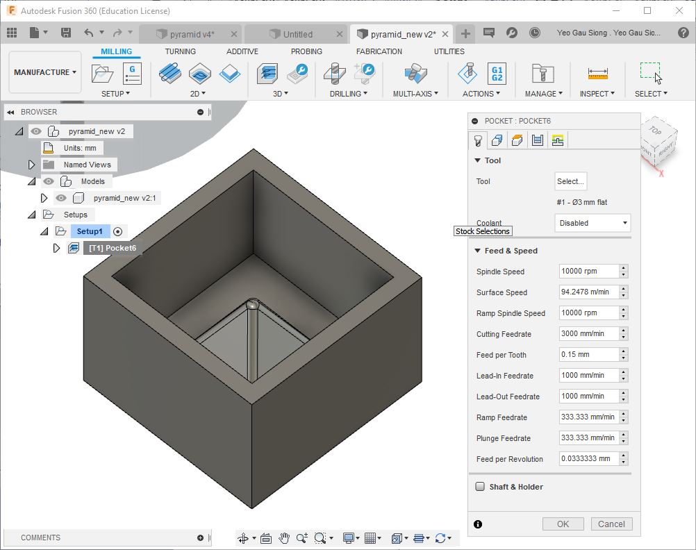
Creating toolpaths parameters for milling process, select Tool tap in the window.
Created a new set of parameters for Feed & Speed, I increased the Spindle Speed and
Cutting Feedrate. Next, select Tool>Select, to create a new set of end mill.
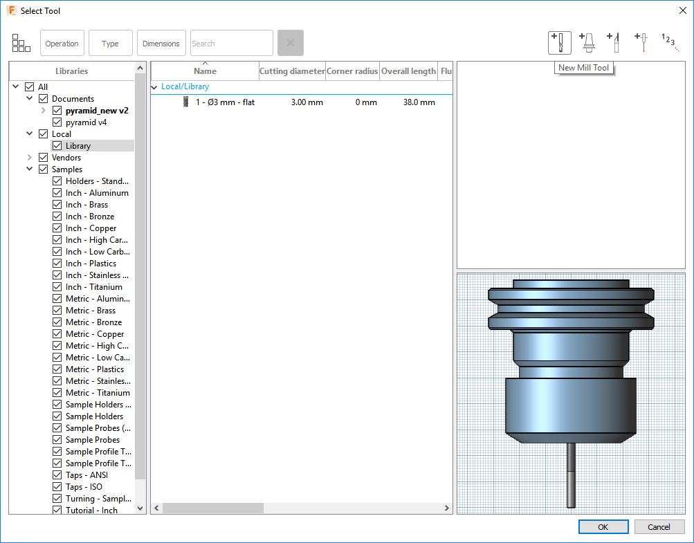
I am using a 3mm end mill, so I created a new cutter and defined it geometry in a local library.
Select Local>Library from the Libraries
Select New Mill Tool to create a 3mm end mill.
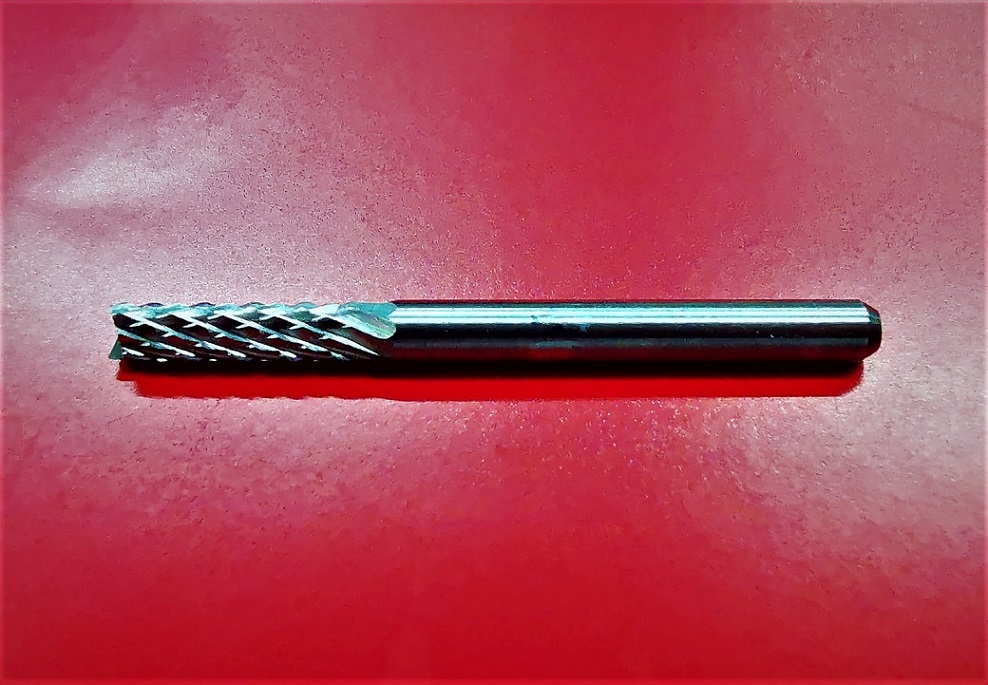
I am milling my mold using this 3mm end mill, it has a 24mm long shaft suitable for milling of my mold.
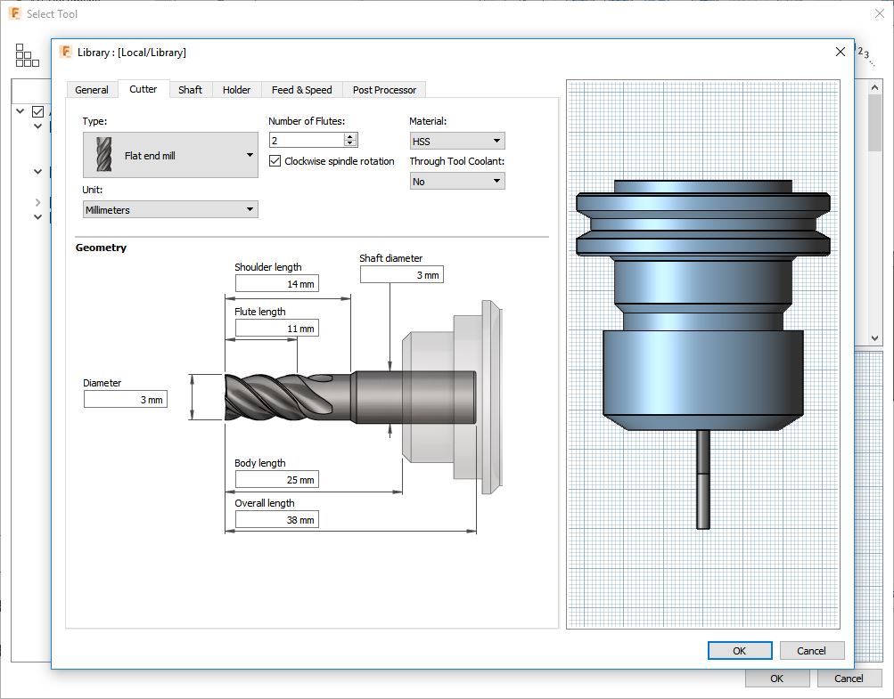
In the Cutter tap, I had created a geometry for my 3mm end mill, this will be the cutting tool for milling my mold.
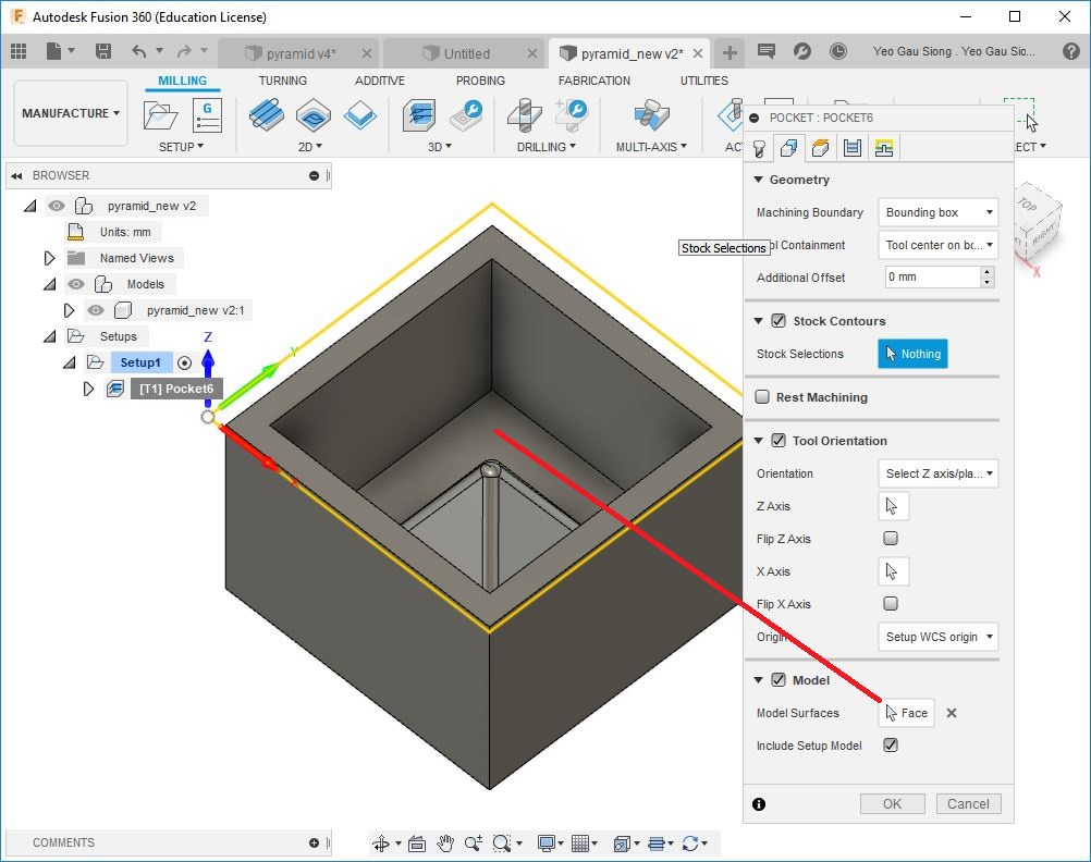
Select Geometry tap in the window.
Select Model Surfaces>select the bottom face inside the mold
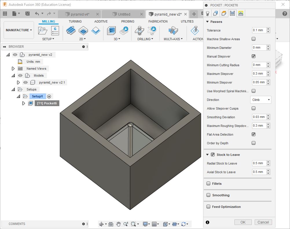
Select Passes tap in the window. I created a new set of parameters for Passes, made changes
to Stepover, Stepdown and Smoothing Deviation, changes made will create a smooth surface
on pyramid walls.
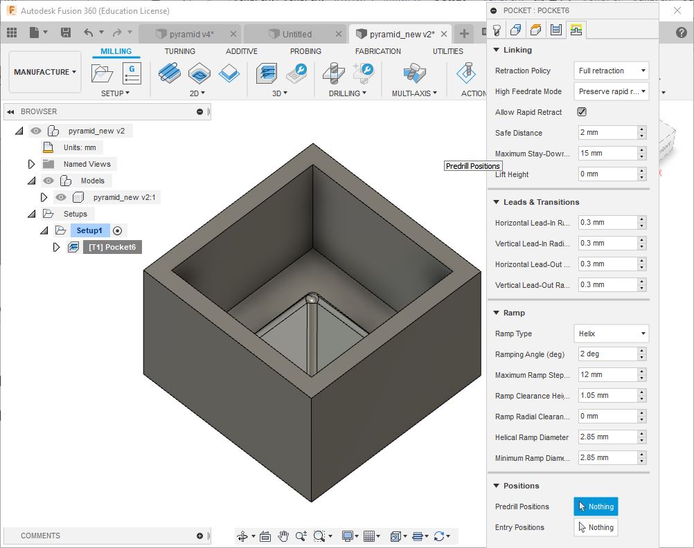
Select Linking tap in the window.
Select>Maximum Stay-Down, this allow me to shorten the time between cuts.
Select>Ramp Clearance Height, this allow me to define clearance for Helix Ramp to start.
Then, click OK.
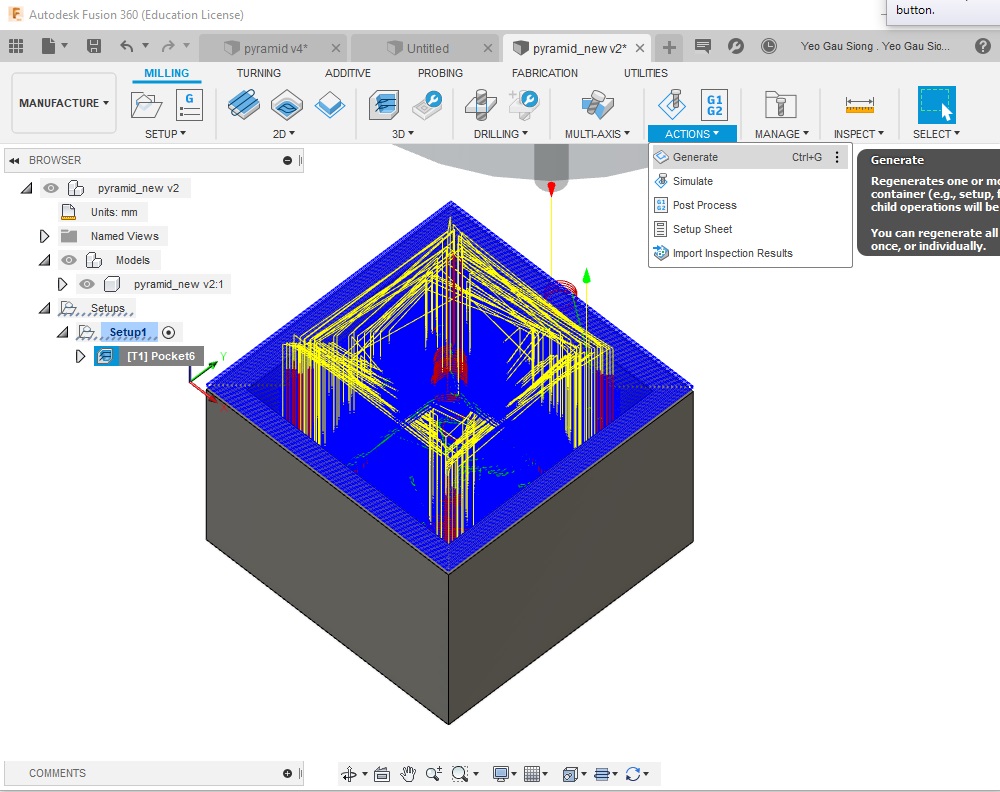
After setting parameter, toolpath was generated before simulates milling process.
To generate toolpath, select Actions>Generate
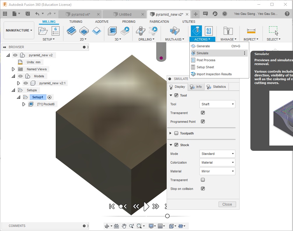
With toolpath generated, I can preview the toolpaths and simulates the stock material removal.
Select Actions>Simulate
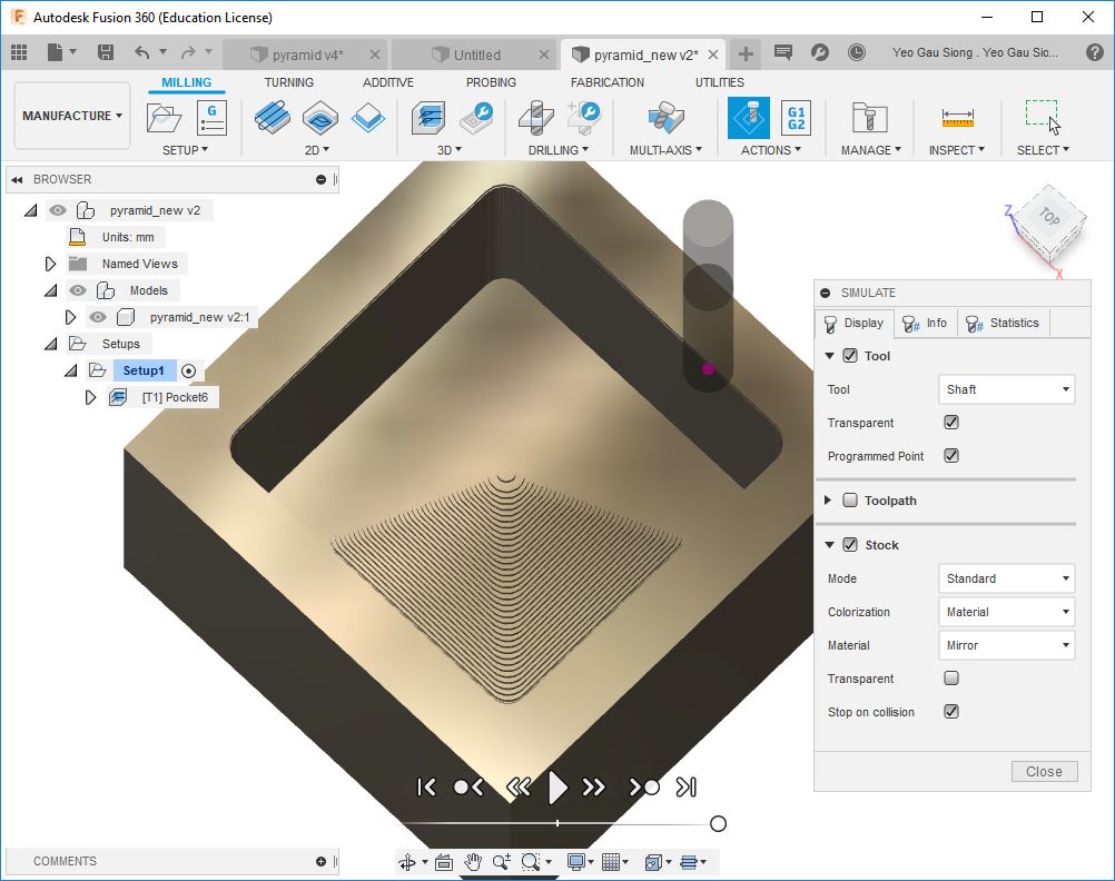
Click the simulate play button at the bottom of the window to start the simulation.
Successfully simulated milling process without collision.
Next, generate machine specific NC code. This will be my G-code to be use on a CNC
machine to mill out my mold.
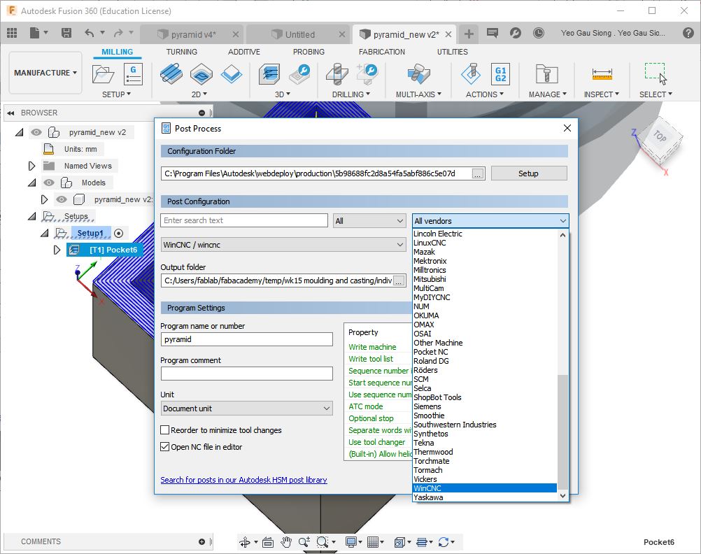
Select Post Process
Select All vendors>WinCNC in the listing to generate the G-code.
Finally, generated the G-code for my design of a 3D one-part mold.
Milling with a STEPCRAFT 420
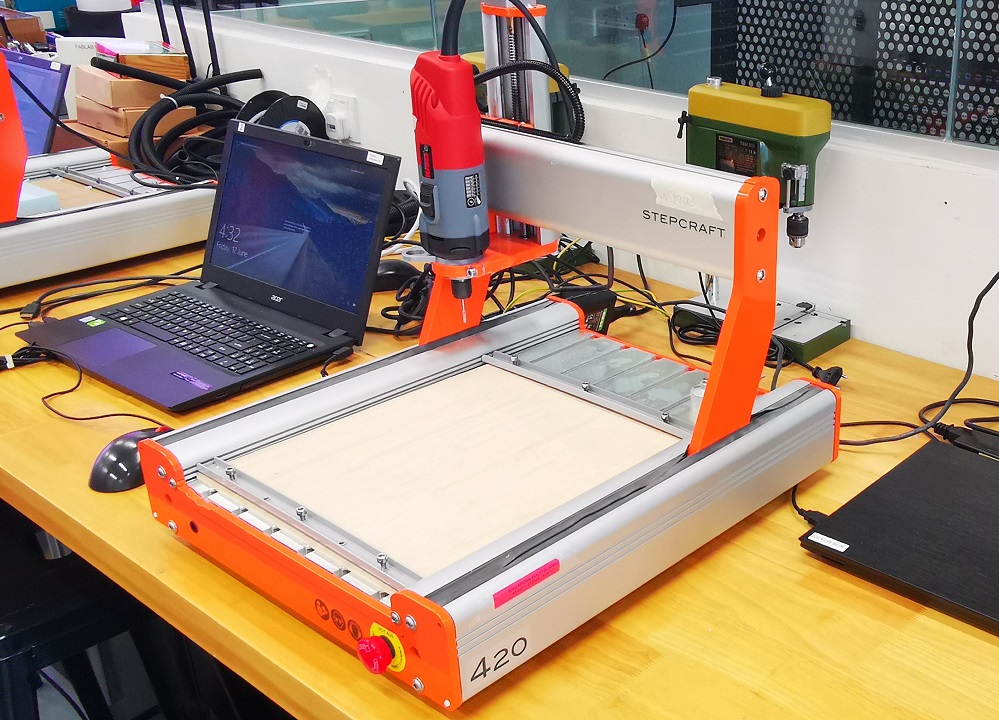
STEPCRAFT 420 allow me to perform a 3-axis milling on my design of a 3D one-part
mold with a 3mm flat end mill.
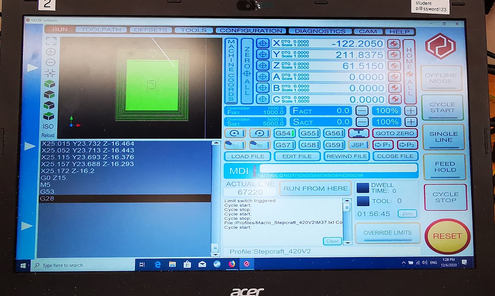
Loaded my G-code onto an UCCNC program to mill my mold on a STEPCRAFT 420.
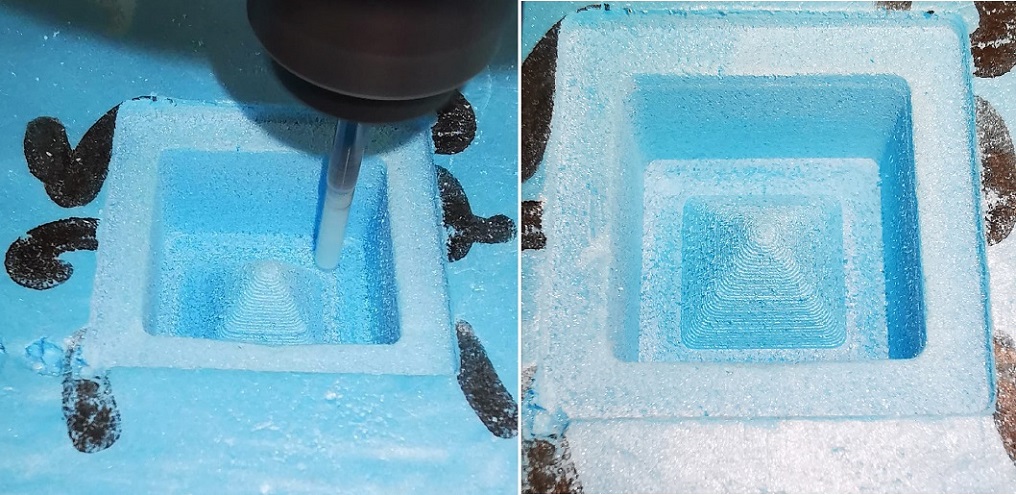
Completed my milling of a 3D mold (positive mold) around the stock (i.e. blue form).
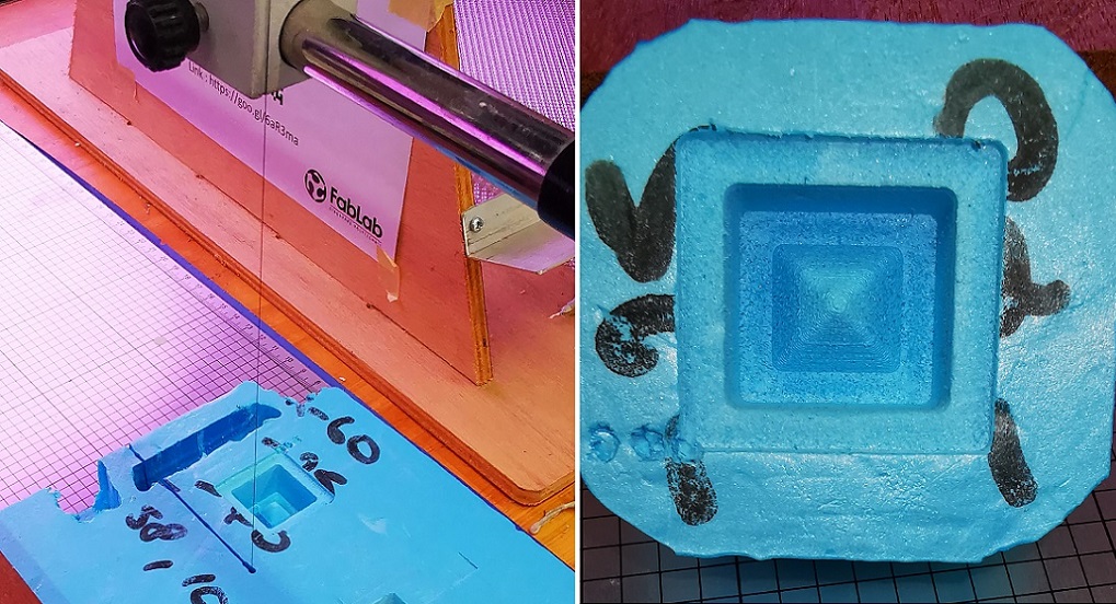
Used a hot wire cutter to cut out my mold from the stock.
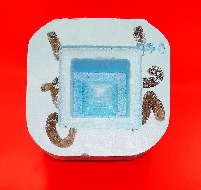
My 3D one-part pyramid mold is ready for casting.
Mold Making with EasyMold
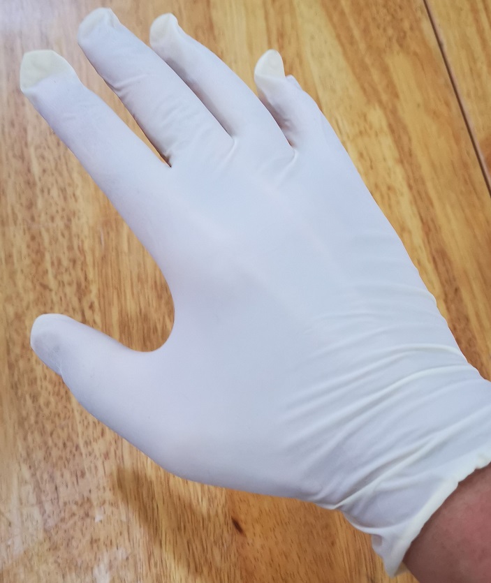
Before casting my mold, I put on glove to protect my hand from the mixture of EasyMold.
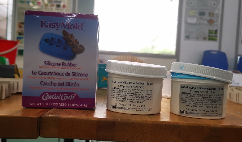
I am using the EasyMold Silicon rubber to make my 3D mold around the stock (i.e. blue form),
instructions can be found here.
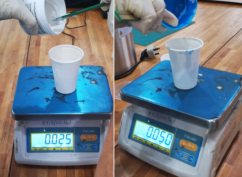
Measure equal amounts of component A and B by weight, 25g of component A + 25g of component B are dispensed into a mixing container.
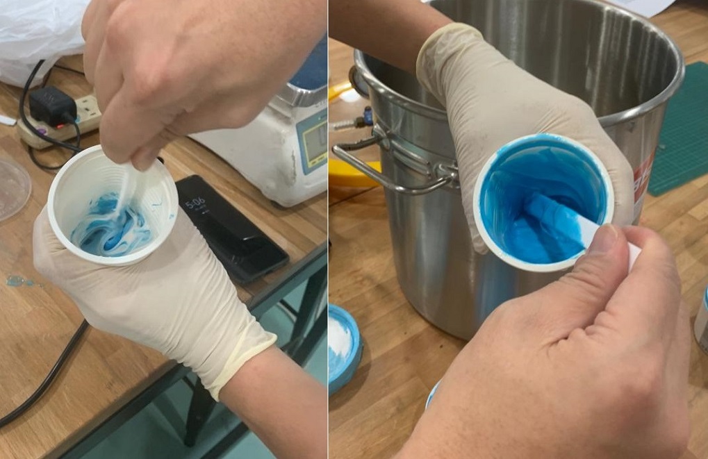
Both components are thoroughly mixed until a uniform colour is achieved. Next is to remove air
bubbles in the mixtures.
Vacuum Degassing EasyMold Mixture
Vacuum degassing is a process to remove trapped air bubbles easily from silicon mixture using
a vacuum chamber and a vacuum pump.
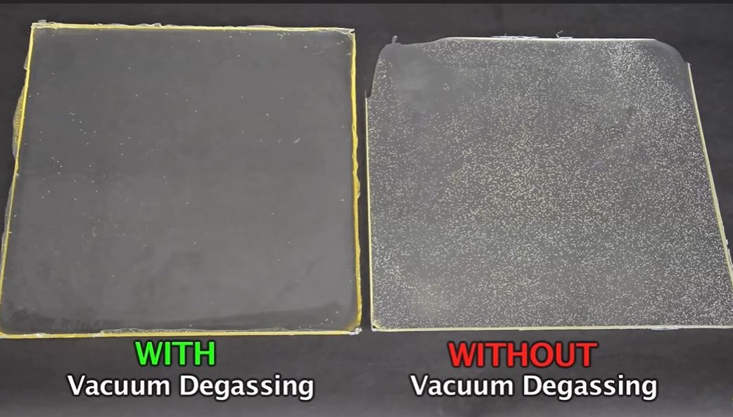
Example of casting with vacuum degassing, left material is casted almost free from air
bubbles. The tear strength on the left is better compare to the right material.
Image reference from on 140520: https://www.youtube.com/watch?v=l7WRGfnJQaM
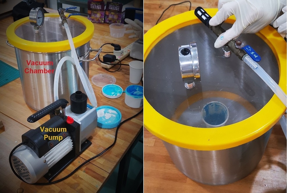
To remove air bubbles from silicon mixture, the mixture in the container is placed in a vacuum
chamber with vacuum valve closed to allow air flow, then vacuum pump is turn on.
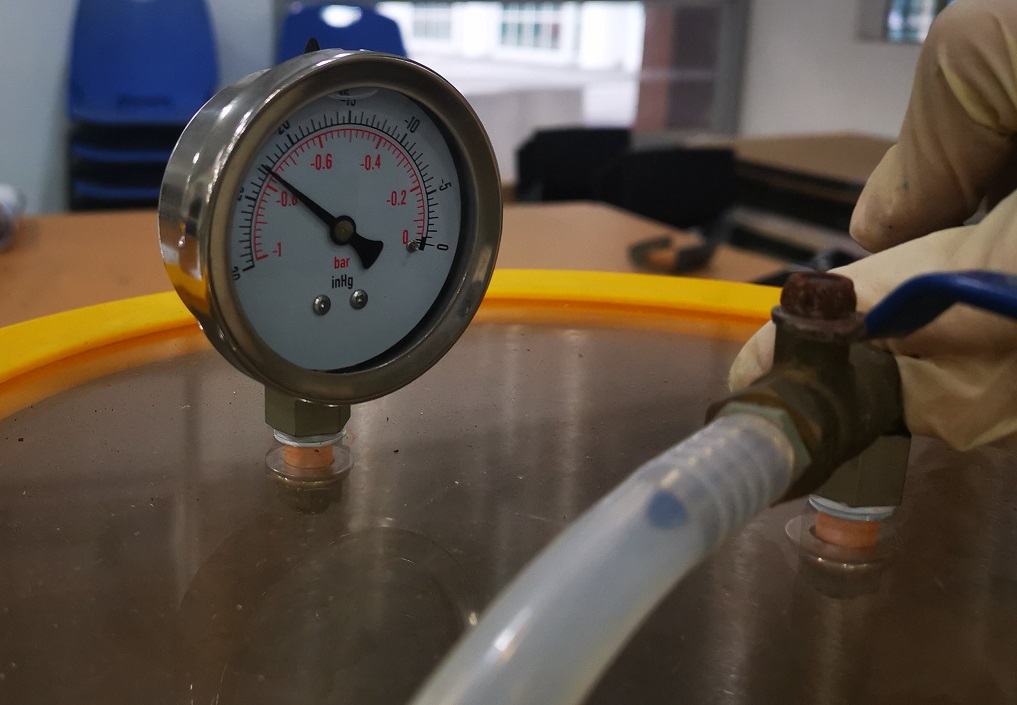
Vacuum pump must pull 29 inches of mercury (2 bar) at a minimum 8 CFM.
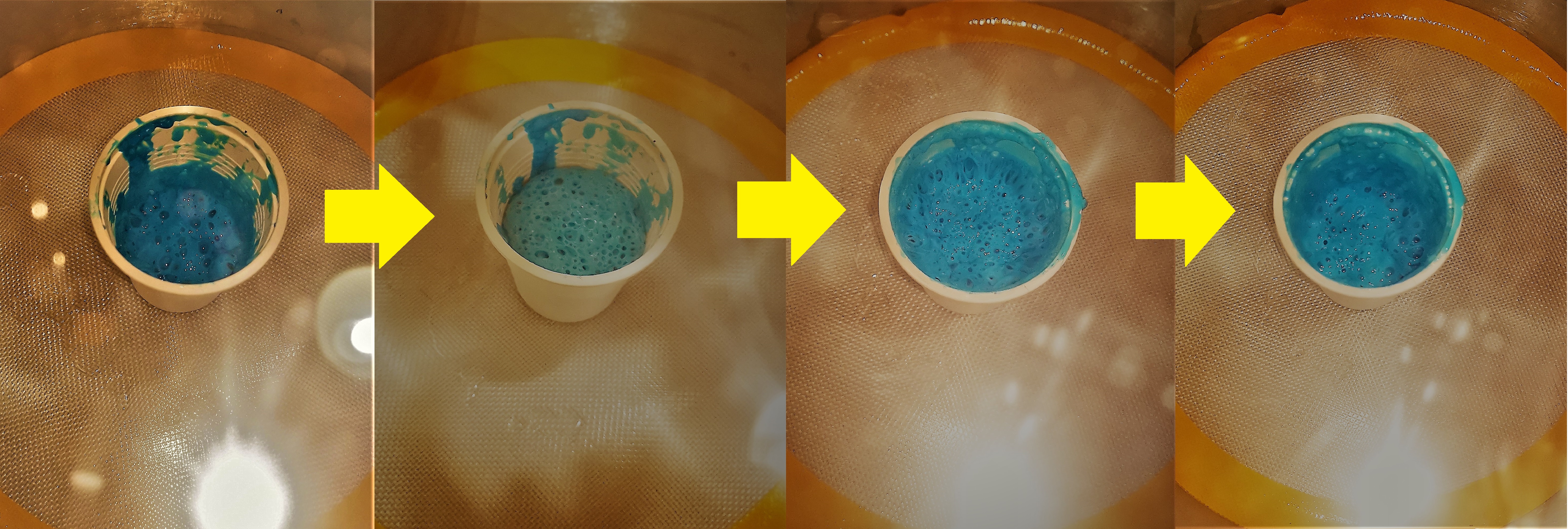
Silicon mixture inside the vacuum chamber for more than 10 minutes, mixture inside the container will rise and fall because majority of bubbles are removed.
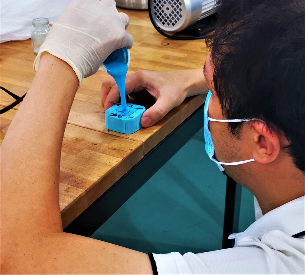
Mixture container is removed from the vacuum chamber, and the silicon mixture is slowly
poured (a thin stream) into one corner of my mold.
After filling my mold with silicon mixture, let it cure for 24 hours at room temperature in a dry environment.
After 24 hours, silicon mixture is cured, my mold is removed from the stock. I had completed making a negative mold with silicone. I will use this silicon mold to cast my model pyramid.
Casting with Epicote 1003
Before casting, I put on glove to protect my hand from Epicote 1003 mixture.
This time I am using Epicote 1003 for my mold casting, this material is...
(1) low volatility,
(2) 5-10 min working time,
(3) resin to activator ratio of 3:1,
(4) 2 hrs cure time
Left container is resin Epicote 1003 and right container is the hardener for Epicote 1003.
Prepared 30mg of resin and 10mg of hardener in a container, both components are thoroughly
mixed (Epicote 1003 mixture is shared by my group to minimise wastage).
Vacuum degassing is not required because air bubbles are very minmium when gently mixing
Epicote 1003 mixture.
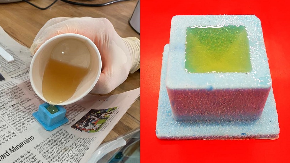
Filling my mold with Epicote 1003 mixture, let it cure for 24 hours.
After 24 hours, Epicote 1003 mixture is cured, and remove casting from my mold.
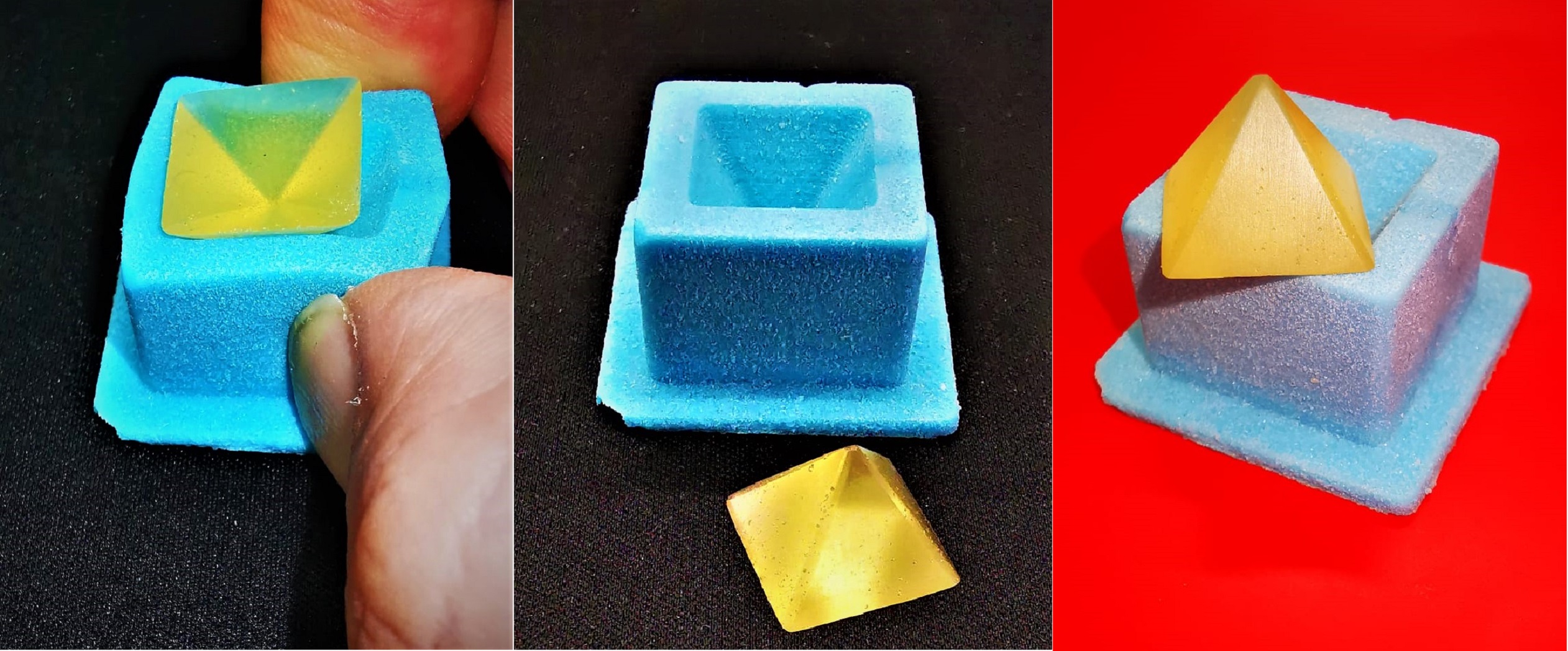
Finally, I had completed making a negative mold with silicone, and done a casting in this silicon mold. With mold, I can cast model pyramid repeatedly.
Design File and G-Code for My 3D Mold
1. CAD file for 3D mold around the stock, right mouse click and save link: wk15pyramidmold.f3d
2. G-code for 3D mold, right mouse click and save link: wk15pyramidmold.tap
What I have learned:
1. It is important for users to understand the information of Safety data sheets for materials used in molding and casting.
2. Following safe working procedures (i.e. PPE used, storage, First Aid measures, etc.) when using materials for molding and casting can prevent accidents and incidents from occuring.
3. Using Fusion 360 combine feature to subtract one body from another, this allow me to design my 3D mold.
4. Simulating a milling process using Fusion 360 can prevent physical milling collision on my 3D mold.
5. Designed and milled a 3D model of one-part mold (positive mold), then make a mold from the milled part, finally cast using the mold.