10. Input devices
This week task is to measure something with the microcontroller that I have designed, this is done by reading the values from the sensor attached to the board.
Group assignment:
the group assignment work is documented in the group page here
Atmega 328p
In this week I will be using the atmega328p board that I have designed, to use it for the inputs and outputs weeks,
to do that I redrew Neil’s design hello.arduino.328P
with the following modification:
- I added LDR as an input
- rgb light as an output.
- LED as an output
- extra free pins to connect external actuators and sensors.
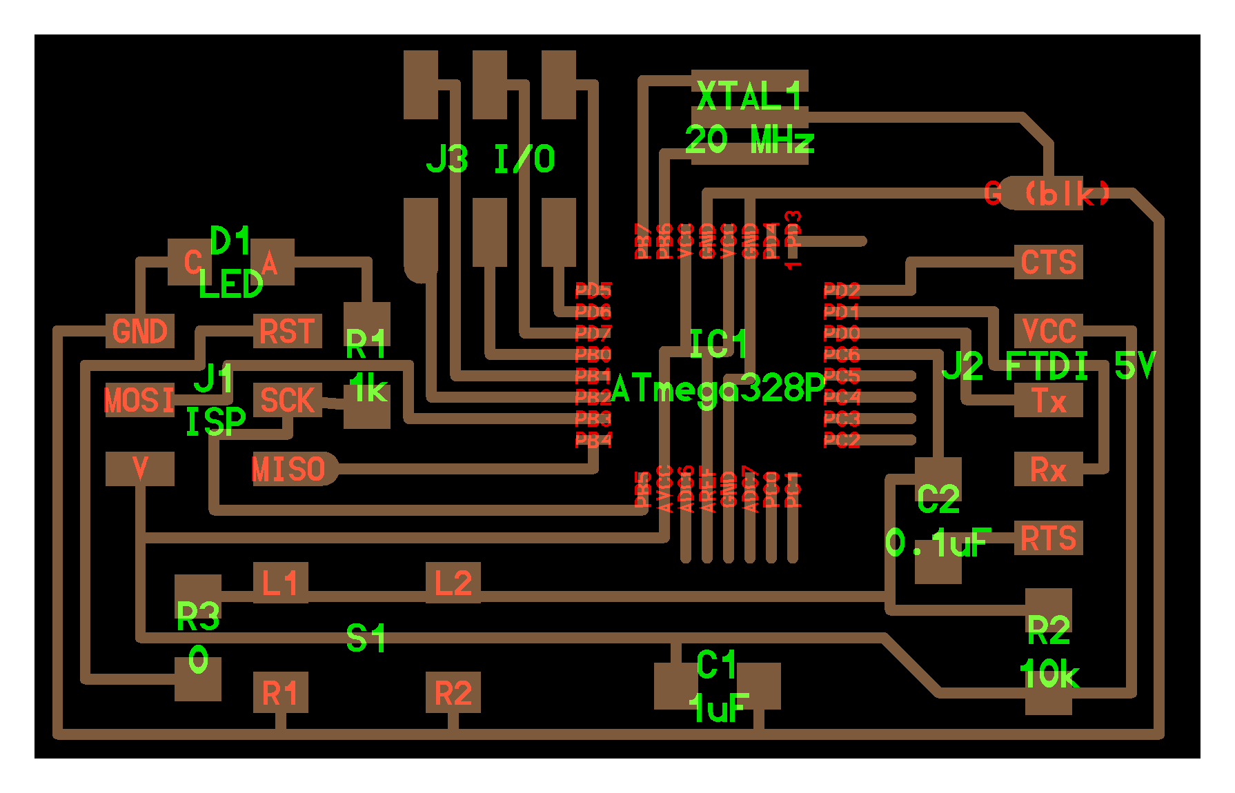
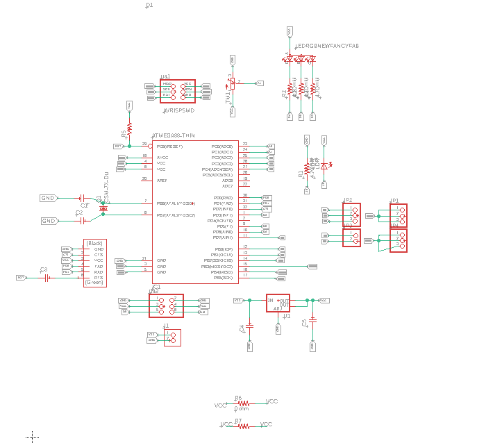
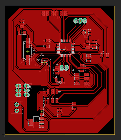
Schematic Diagram:
I just followed the same procedures as my electronic design week, I used eagle software to draw the schematic and using the add component tool, to add the components used in the board,
then as usual preparing the board layout which took most of the time where I have to spend most of the time on the routing, but this time I created a common ground to ease the routing where we can reduce the number of traces, to do that I select polygon on the left tool bar
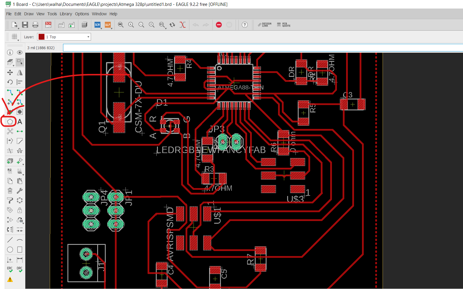
then highlighted the area around the components, and then selecting Ratsnets
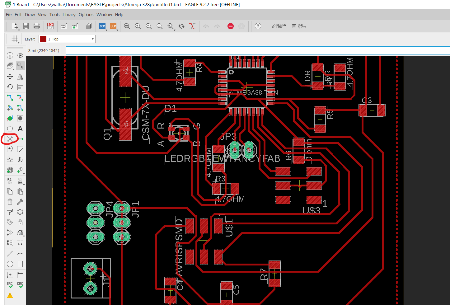
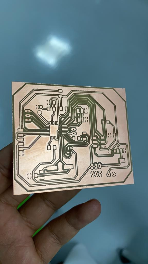
once I was done with it my final board was as follow:
now it is time to prepare the file for the milling, I’m using the flatcam which is a Free and Open-source PCB CAM, this time as our instructor hashim nabil recommended us,
to use the flatcam I needed to export the gerber file from eagle
to do thath I have to click on manufacturing tab
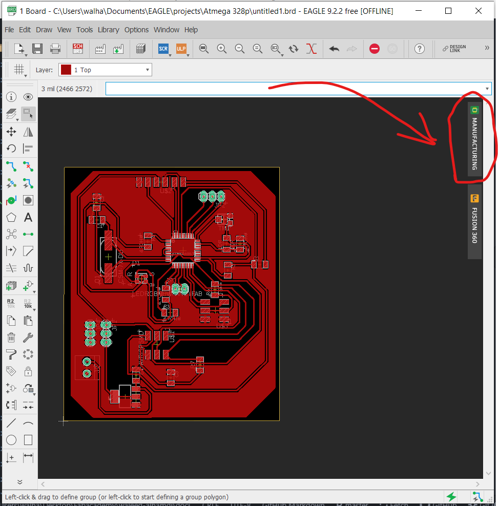
then cam,
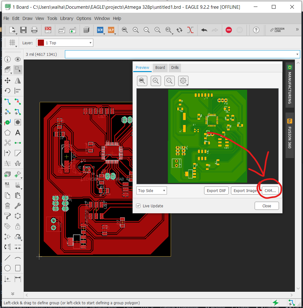
after that process job
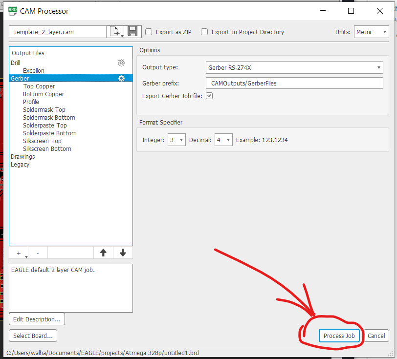
then I just launched flatcan and opened the gerber files that was created for the traces and outlines, and opened the Excellon files for the drills,
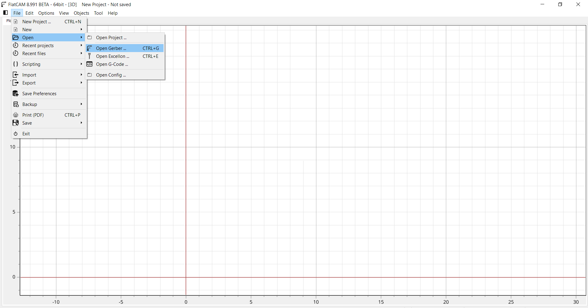
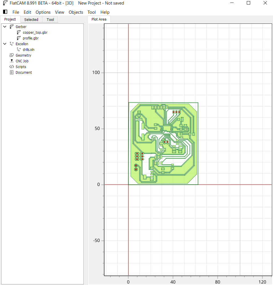
As shown below the screenshot of the software with used settings:
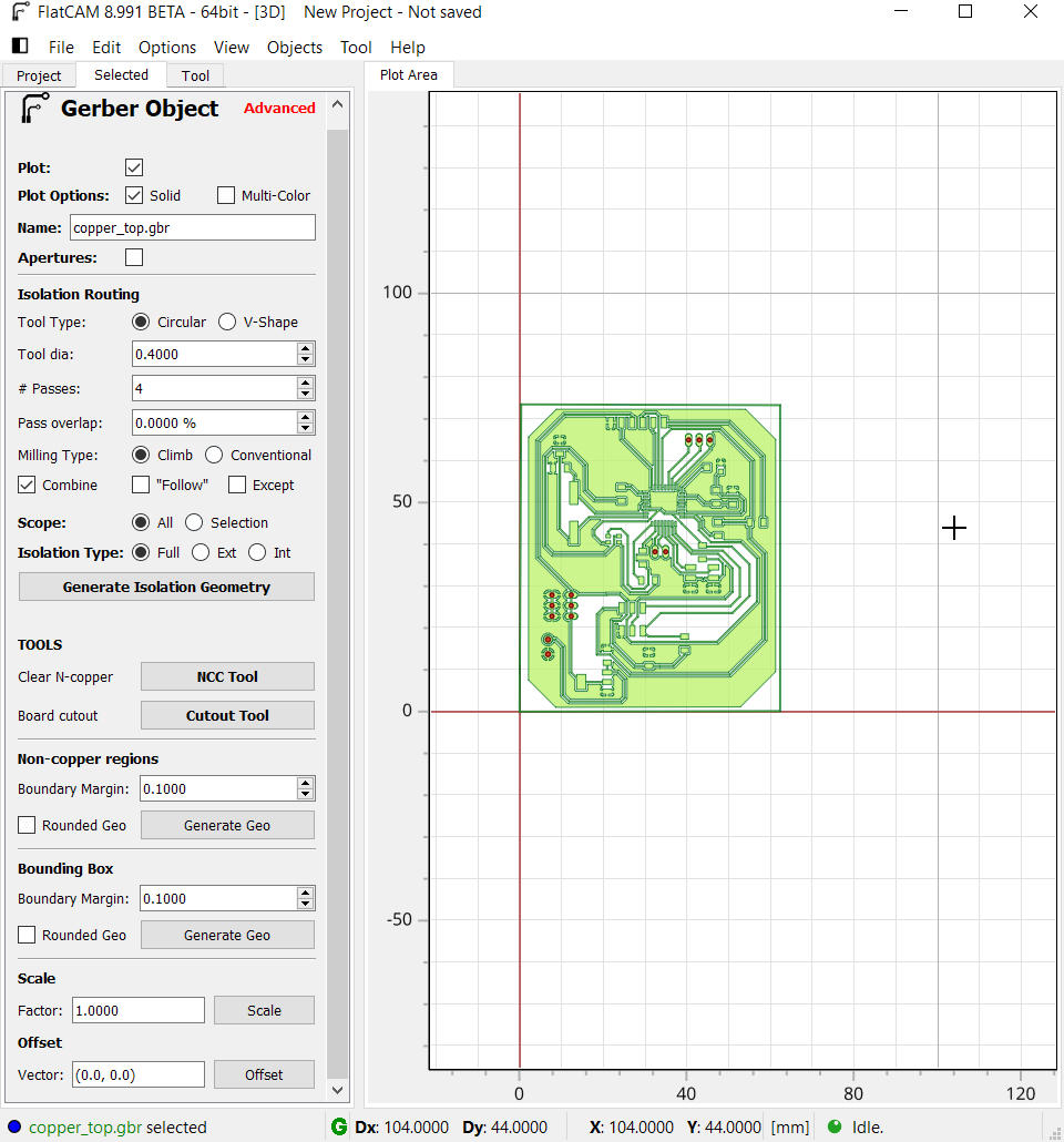
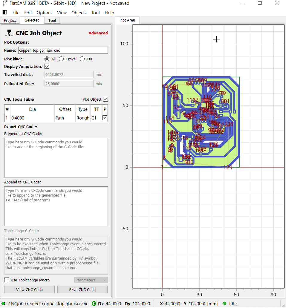
- traces:
1 - generate Isolation geometry: - tool diameter= 0.4mm - number of passes= 4. - passes overlaps= 60%. - check the combine check box.
2- generate the CNC object files for traces with the following settings: Z= -0.1mm, End move Z= 60, Feedrate X-Y= 240, feedrate Z= 80,
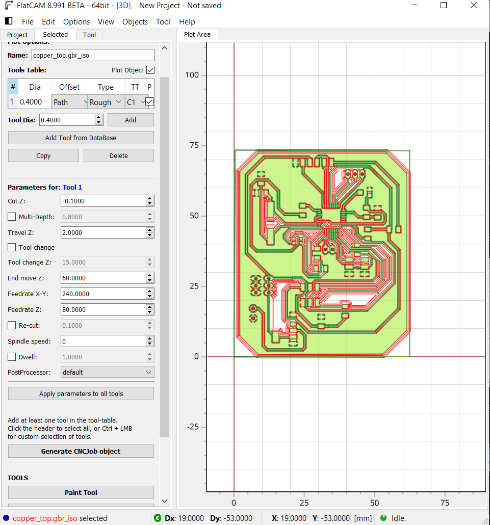
then by clicking on generate CNC object files:
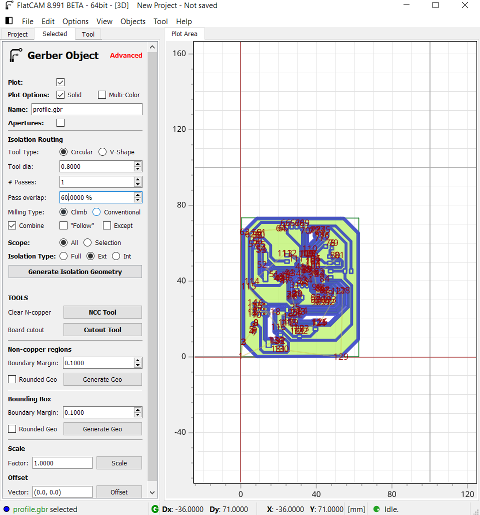
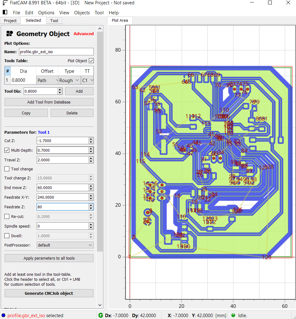
- Outline:
1 - generate Isolation geometry: - tool diameter= 0.8mm - number of passes= 1. - passes overlaps= 60%. - check the combine and the external isolation check boxes.
2- generate the CNC object files for traces with the following settings: Z= -1.7mm, check multi-depth= 0.7, End move Z= 60, Feedrate X-Y= 240, feedrate Z= 80,
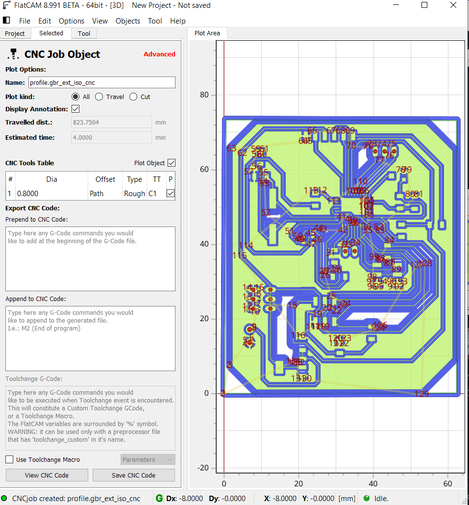
then I used the SRM 20 CNC machine to mill my board, to do that I just followed the same procedure in electronic production week, and the milling process was very nice and smooth,
then I just soldered the components,
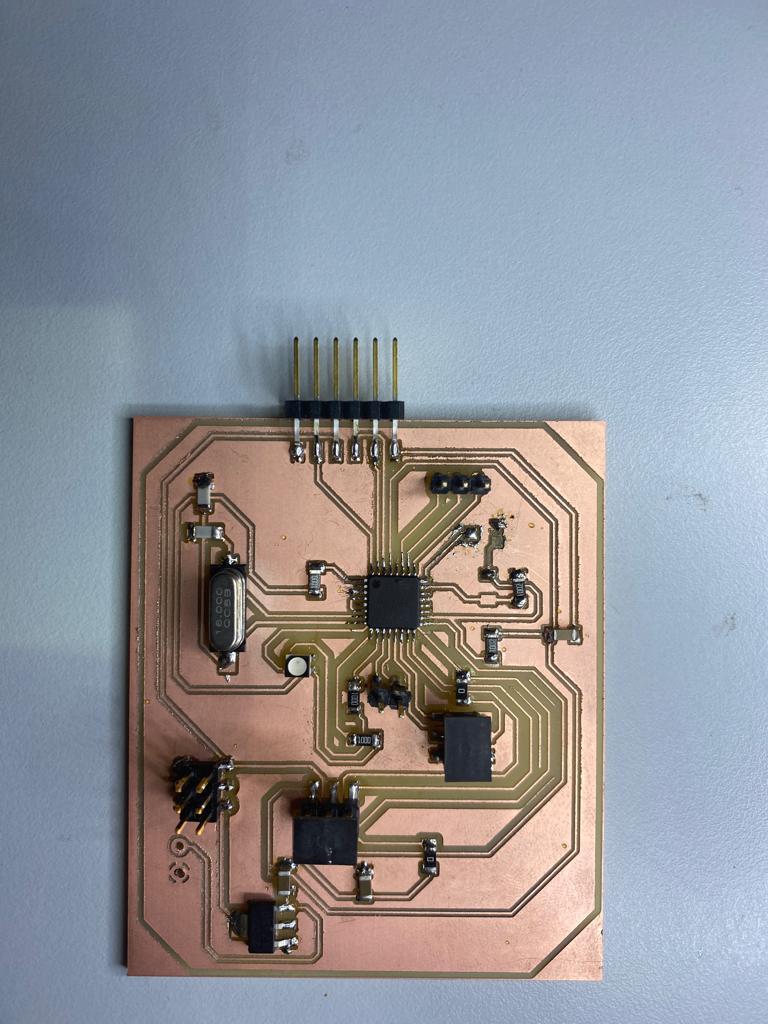
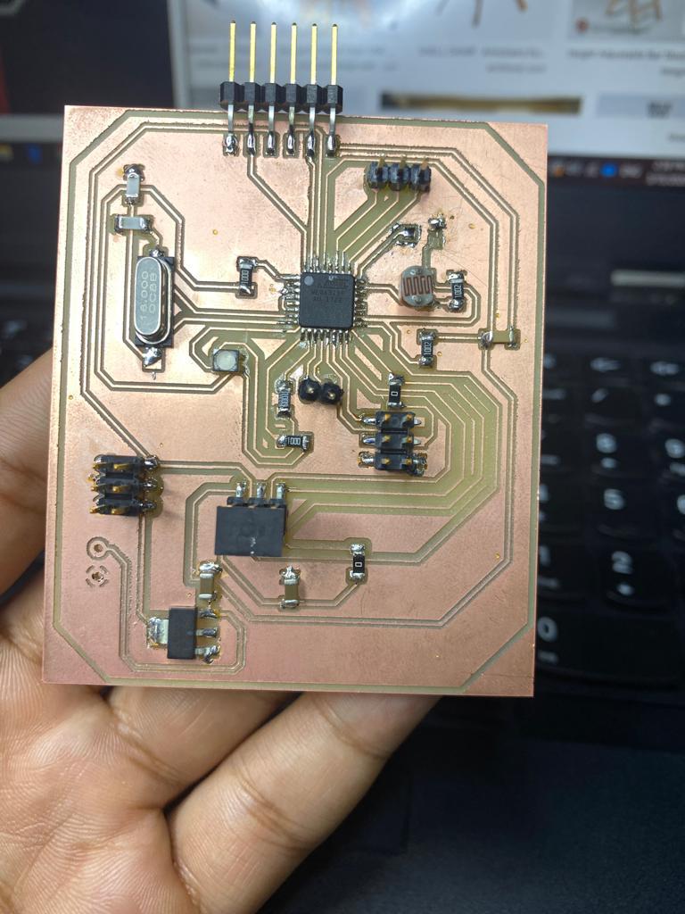
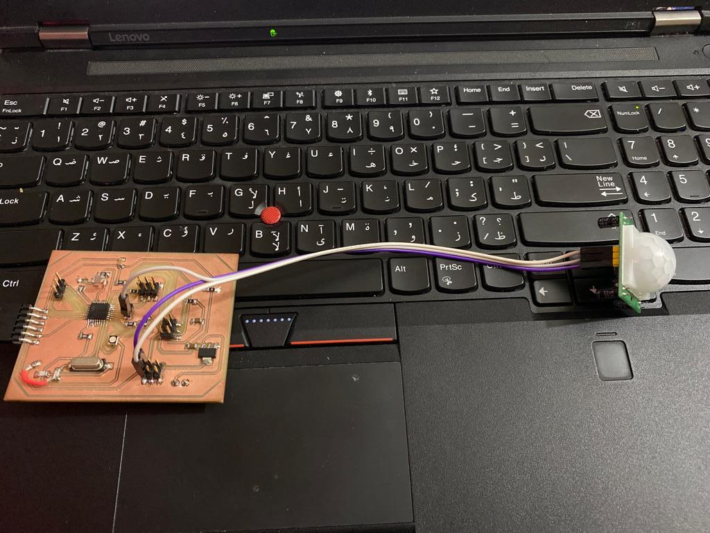
as you can see from the schematic that I have attached LDR sensor to read the brightness of the environment also I left an analog and digital free pins so that I can attach external sensors.
PIR sensor
To start with, I have to go through the data sheet, to get myself familiar on how the motion sensor works, to know what the operation power is and the pinout, I referred to the following link for the data sheet and the PIR sensor model number I’m using is HC-SR501,
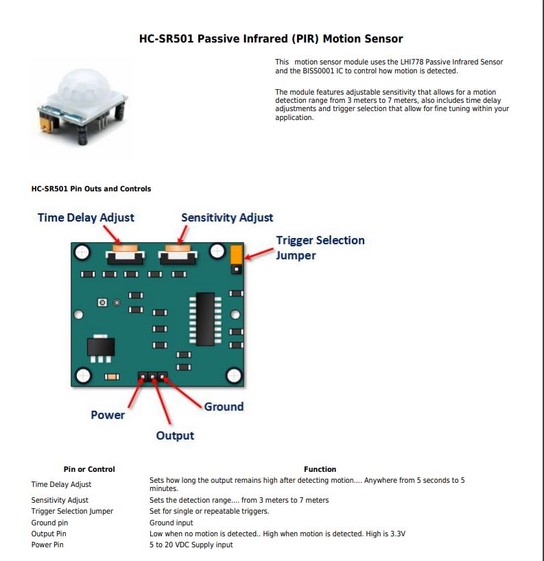
PIR connection
I made the connection as the following:
PIR sensor >>>>>>>> Waleed’s board
GND >>>>>>>> GND
OUT >>>>>>>> D7
VCC >>>>>>>> VCC
PIR coding
I wrote a code so that whenever a motion is detected the built in led in my board will light up, the built in LED is attached to the pin 13.
The pinMode(pin, mode) syntax is used to configure the specified pin to behave either as an input or an output.
digitalWrite(pin, value) syntax is used to set the corresponding PIN value: 5V (or 3.3V on 3.3V boards) for HIGH, 0V (ground) for LOW.
The if() statement is the most basic of all programming control structures. It allows you to make something happen or not, depending on whether a given condition is true or not
int ledPin = 13; // LED on Pin 13 of Arduino
int pirPin = 7; // Input for HC-S501
int pirValue; // Place to store read PIR Value
void setup() {
pinMode(ledPin, OUTPUT);
pinMode(pirPin, INPUT);
digitalWrite(ledPin, LOW);
}
void loop() {
pirValue = digitalRead(pirPin);

  if (pirValue == HIGH) { // check if the sensor is HIGH
    digitalWrite(ledPin, HIGH);      // turn LED ON
    Serial.println("Motion detected!");
    delay(1000);                   // delay 100 milliseconds
  }
  else {
    digitalWrite(ledPin, LOW);       // turn LED OFF
    Serial.println("Motion stopped!");
    delay(1000);                   // delay 100 milliseconds
  }

}
Attempt to read LDR
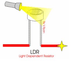
I started by reading and learning about the LDR sensor, LDR stands for light dependent resistor, it has variable resistance that changes with the light intensity that falls upon it, then I tried to read the built in LDR sensor values which is attached to pin number PC0/ A0,
Working principle of the ldr
The LDR works on the principle of photo conductivity which is an optical and electrical phenomenon in which a material becomes more electrically conductive due to the absorption of the visible light. So that when the light falls on the LDR surface, then the material conductivity reduces (for more details you might refer to the link).
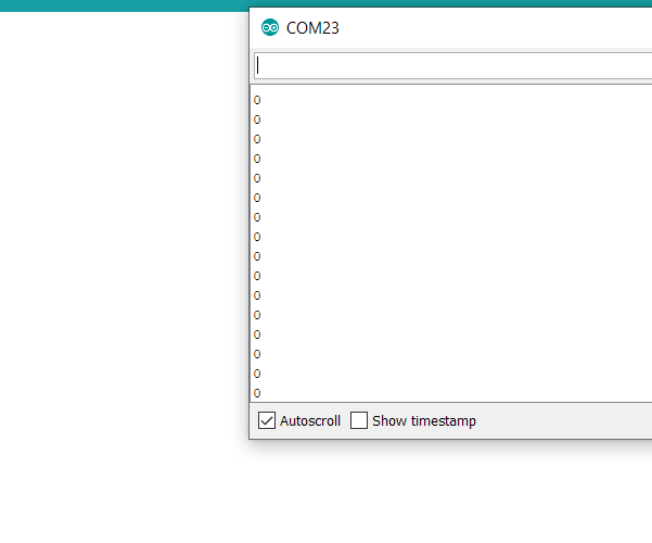
I wrote to following code,
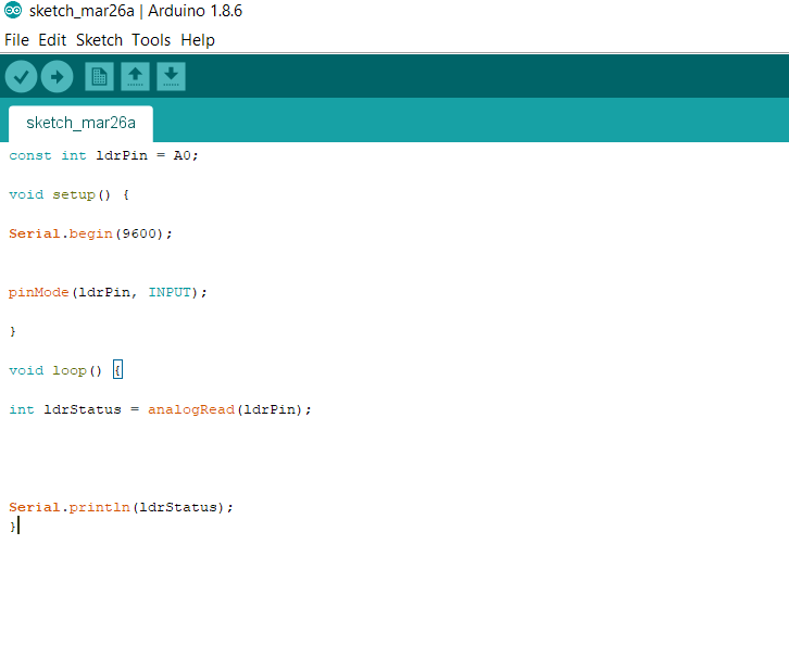
but unfortunately all what I get from the serial monitor was only 0s,
debugging LDR
I followed different procedures to solve the problem as the following:
1- The code
I doubled checked the code I have wrote but there was no problem with it.
2- The schematic
also I assured that the schematic connection of the ldr was correct and it was connected to pin PC0/A0.
3- The board
This is where the problem I think is, where I found there is a short circuit in the board and I could not fix the problem due to not having the soldering tool, or the multimeter at home to verify the problem, THANKS TO COROANA!
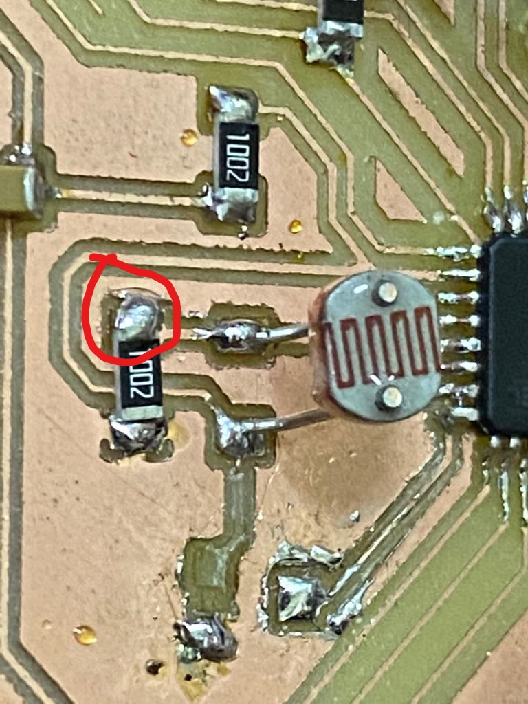
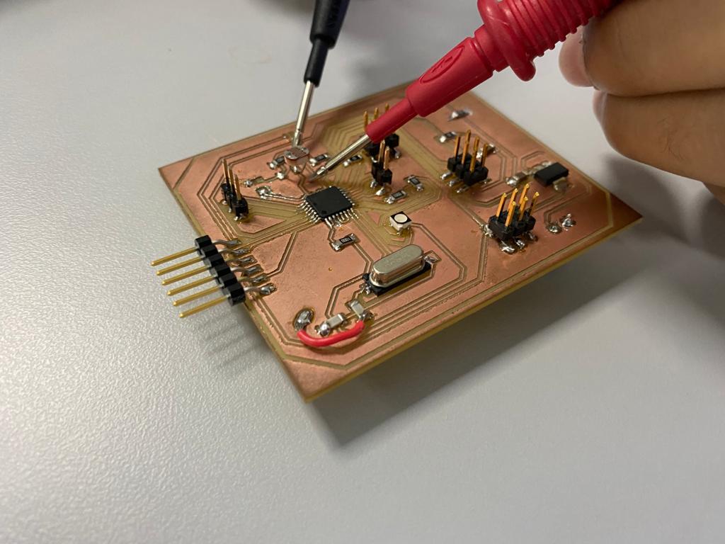
Update 11/10/2020
I confirmed the problem using the multimeter where there was a short-circuit in the board,
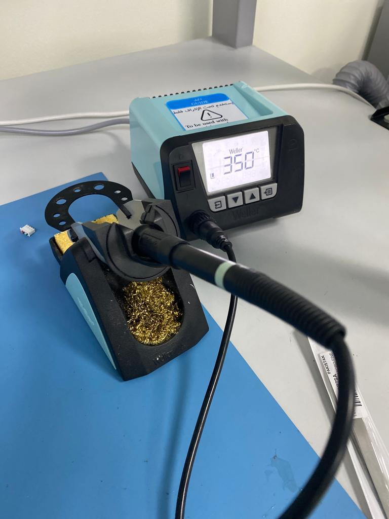
I fixed the problem using the soldering tool to remove the excessive solder from the board,
Download Files