7. Electronics design
This week is about electronic design.
The group assignment is:
use the test equipment in your lab to observe the operation of a microcontroller circuit board. Test equipment is:
• Regulated power supply
• Digital multimeter
• Oscilloscope
• Logic analyzer
This is our group assignment
The individual asignment is:
• Redraw an echo hello-world board
• Add at least a button, a LED and a light sensor (with current-limiting resistor)
• Check the design rules, make it and test it
(extra credit: simulate its operation)
For the board I chose the ATTiny 45.
I looked up the components in the link for the individual assignment
1 ATTiny 45
2 Resistor 10K
1 Resistor 1K
1 Resistor 5K
1 Capacitor 1uF
1 ISP 6 pin
1 FTDI 6 pin
1 Button
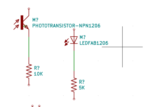
1 LED Red LEDFAB 1206
1 Phototransistor NPN 1206
I added 1 10K Resistor and 1 5K Resistor to the componentlist. On the site of Anne Vlaanderen I saw in the shematics of her ATTiny Y44 the LED needs a 5K resistor and the Phototransistor needs a 10 K Resistor.
Design in KiCad
Time to design the board in KiCad
In KiCad I created a new project ATTiny 45.

I clicked on the .sch file to start designing.
When I started I did not have the FabAcademy library for KiCad. That gave me to many choices for example for the ATTiny 45: five different types. Wich one to choose. Since the FabAcademy only uses one type of the ATTiny the choice is simple. With help of a co-student I imported the FabAcademy-symbols and footpfints into KiCad.
I clicked on the Place Symbol button.
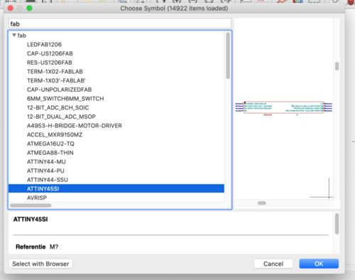
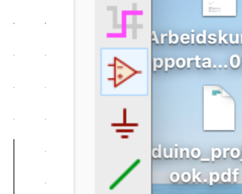 The cursor becomes a cross. Click in the scheme and click. A list of (component)symbols appears. I filtered on “fab”. The list is now narrowed down to the components FabAcademy uses.
First I chose the ATTiny 45 SI, then all the other components
 2 Resistor 10K
1 Resistor 1K
1 Resistor 5K
1 Capacitor 1uF
1 ISP 6 pin
1 FTDI 6 pin
1 Button
1 LED Red LEDFAB 1206
1 Phototransistor NPN 1204

STOP! You gonna need a bigger boat
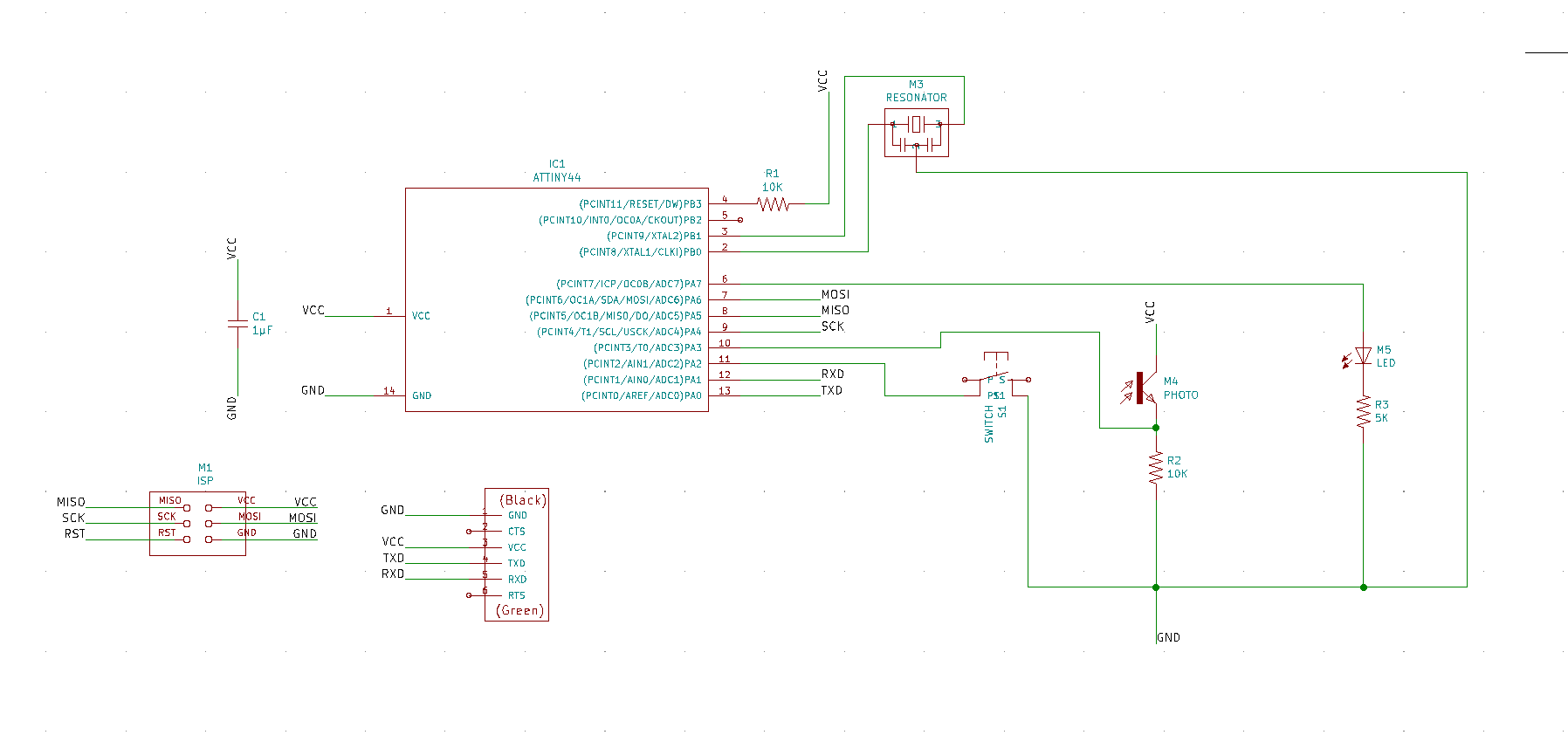
The ATTiny 45 is not the right board for this project. It needs a Resonator and then there will be not enough pins for the button, the LED and the phototransistor. I switched to the ATTiny 44-SSU
I had to adjust the list of components
1 ATTiny 44 SSU
2 Resistor 10K
1 Resistor 5K
1 Capacitor 1µF
1 AVRISPSMD
1 FTDI 6
1 Button
1 LED Red LEDFAB 1206
1 Phototransistor NPN 1204
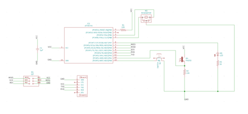
First I placed the ATTiny 44 SSU
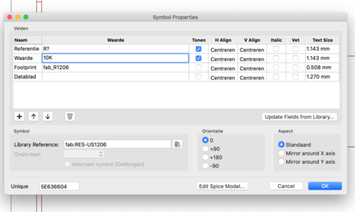
Then I placed the trhree resitors I needed. With Right Mouse Click Properties > Edit Properties I could change value from RES-US1206 into 10K and 5K. I did the same for the capacitor from 1µF.
All the components were now in the scheme.
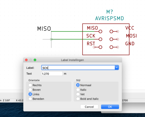
Then I drew the connections on the ISP. Pretty staight forward: MISO should be connected to MISO on the ATTiny, MOSI to MOSI et cetera. I used the Place Wire button on the right (the green line)
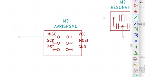
With Add Label I labeled the wires. I made sure to use CAPS so KiCad would recognize the labels. KiCad is also using caps for labels.
I did the same with the FTDI.
From documentation from a former FabAcademy I found out that the LED needs a 5K resistor and the Phototransistor needs a 10 resistor. So I conneccted those With Right Mouse Click > Orientation I rotated the resistors to allign them with the LED and the phototransistor.
Then I labeled the connections for the pins on the Tiny. First the ones that ar dedicated
PIN 1 VCC
PIN 14 GND
Pin 4 RESET
PIN 5 CKOUT for the Resonator
PIN 2 CLK1 for the Resonator
PIN 7 MOSI
PIN 8 MISO
PIN 9 SCK
This leaves 6 pins open. I labeled them as follows
PIN 6 LED wich of course is used by the LED
PIN 10 RX is for recieving, goes to the FTDI
PIN 11 TX is for transmitting, goes to teh FTDI
PIN 12 Phototransistor for the Photottransistor
PIN 13 Button for the switch button.
I hope this works out wel. I put RX an TX next to each other because they both hev to go to the FTDI. Same goes for the Phototransistor and the butto wich go both to the Tiny. The LED also, lets hope wires won’t cross.
The LED, de Button and the Phototransistor have to connedted to their pins and to GND. The Phototransistor must also be conneted to VCC
Annotate Schematics
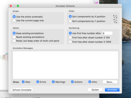
Click on Annotate Schematics in the Tool menu. A window opens. Click on Annotate. All the components will get a letter and number. Resistors will get R1 R2 R3 et cetera, Capasitors C1 et cetera.
Assigning footprints
I wanted to assign footprints to the components. I got this message
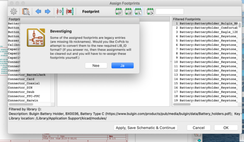
I clicked Ja en the this message appeared.
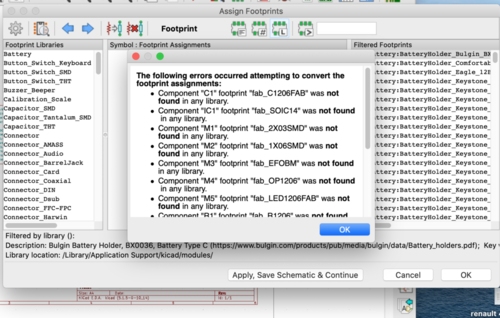
I did not know how to solve this problem so I checked the documentation of some 2019 students. It appeared that I had to select the Fab library to match my components with the library for correct footpronts.
When I selected the Fab-library I could make a match

I did this for all the components on the list.
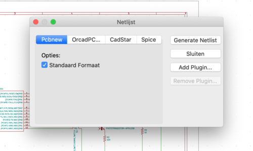
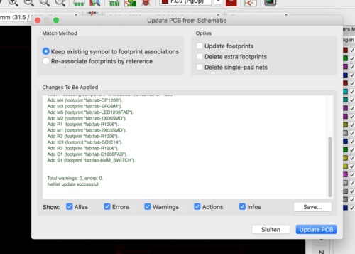
I then clicked on Generate Netlist and in the pop up window I clicked on Generate Netlist
I went to the PCB editor to Update PCB form Schematics. The first time I did that not al the components on the PCB had a code or name. It apperad that in the Update PCB to schematics I did not checked all the checkboxes. When I did that all the components had codes or names.
Click Close to go to the PCB Editor. Mouse click to place the PCB.

Go to File > Board Set Up to set the Design Rules.

I set 0.39 mm for the tracers and 0.4 mm for the clearence. The other variables didn’t need to be canged.
Time to place the tracers.
I noticed that two connections on the FTDI were missing. The RXD and the TXD. I checked and saw that I had labeled these connections on the Tiny as RX and TX. So KiCad did not recognized these connections. I fixed it by relabeling RX and TX on the Tiny. I also shortend the names of the components to make the PCB a bit simpeler.
My start strategy is
• Place the Tiny in the middle
• Put the FTDI at the side
• Put the header at the other side
• Connect all the VCC
• Connect all the GND
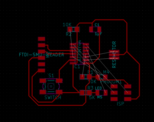
This strategy seems to fail, since the Resoator is locked up
Back to the drawingboard
I tried another configuration of the components and I almost got is.
A slightly different configuration but again, almost…
Since the trouble is on the right hand side of the PCB, with the switch, the phototransistor and the TXD and RXD I decided to change their order on the pins. I hope there will be less overlap now.
To bad, problem not solved. Back to the original schematichs, but now with the photortransistor on pin 4 and the 10K resistor on pin 5. Hoping this will solve the problem in version 3.
It did not.
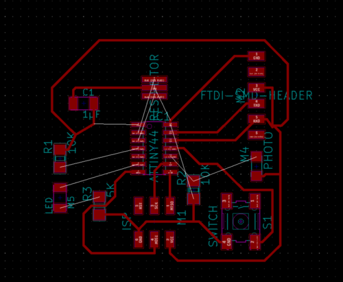
I changed the TXD to pin 13, the RXD to pin 12, the Switch to pin 11 and the phototransistor to pin 10. I did that because it seemed to me that there was the overlap problem. But no. I ended up with version 5 with two missing links.

I have now two versions: version 3 with one missing link and version 5 with two missing links.
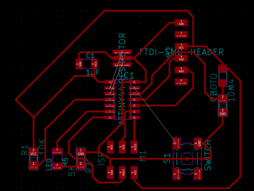
Henk helped me to solve the missing link in version 3 by moving the Phototransistor and the 5K Resistor to the right hand site of the board and making the nescessary connections.
Conclusion: do not adjust the schematic, but keep looking for a solution.
What I did not realize was that I made the new PCB in default design rules. After I changed the Clearance to 0.4 mm and the track to 0.39 mm and ran the Design Rule Checker it gave a lot of errors. And I had to change every track because the were to thin.

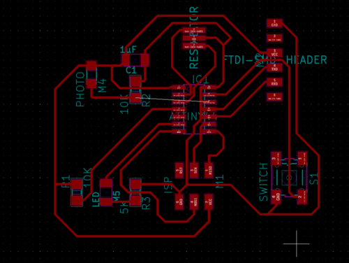
I changed all the thin tracks to 0.39 mm, The PCB is okay now.
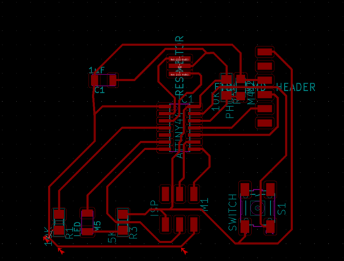
Only thing to be done is drawing the edge. I did theat with the edge tool in the right hand side toolbar.
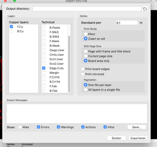
Time to export the file.
Go to File > Export and choose SVG. A windows apears:
Check
• F.Cu
• Edge Cuts
• Black and White
• Board Area Only
• One file per layer.
Then I opened the files in Photoshop 1000 pixles/inch and saved them as .PNG. They look a lot like the files we used during the Electronic production week ;-)

Milling
In MOD’s the PNG files became invisible because I left the alpha channel untouched. Then I tried the SVG file. That seemed to go okay, but in the result the tracers were way to narrow.
Strange becaus in the Boarg setup I entered 0.39 mm for the track width and 0.4 mm for the clearence. The lines in the PCB are also 0.39 mm.
Perhaps it was the SVG and/or the alpha channel.
I exported new SVG files (just to make sure) opened them in Gimp, cleared the alpha channel, and saved them as PNG.
This time it worked: the tracers were fine.
Tme to solder
I started with the ATTiny, looked for the dot and positioned that on the GND.
I continuede with the resistors, the capacitor and the resonator. All components that have no orientation.
What are left are the LED, the Phototransistor and the switch.
The LED.
I thought the green line markt the anode (+) side. I should have checked the net for “recognise the anode on a smd led” witch I later did. The green line marks the cathode! The line represents the line on the cotodhe side in the LED symbol.
I desoldered the led, at least I tried with the heat gun, the desoldering iron and the soldering iron. This operation nearly ruined the contacts. But I was lucky.
The Phototransistor
I tried to find the polarity of the Phototransistor. It is marked with a “missing corner” but I could not find wether that was the collector (anode, vcc) or the emitter (cothode, gnd).
Testing the board
I connected the board from the Electronic Production week to my E|cho Board. I did this with the help from the documentation of Tessel’s website. I had to connect pin 1 of the one board to pin 1 of the other. With the help of Tessel’s documentation I figured out wich pins they are. Just like her I marked them with a black dot.
Trouble shooting
I entered the usb-board in my com puter en typed in command line
avrdude -c usbtiny -p t44
I got this error message
avrdude: initialization failed, rc=-1 > Double check connections and try again, or use -F to override > this check.
avrdude done. Thank you.
Just to make sure I switched the cable but I got another error message. At least I knew the first orientation of the cable was correct.
MacBook-Pro-van-Rinke:~ Rinke$ avrdude -c usbtiny -p t44 avrdude: Error: Could not find USBtiny device (0x1781/0xc9f)
avrdude done. Thank you.
So I had to check the connections like the message said. I found is soon. Pin on the ISP had a loose contact. I soldered is again.
Second time I got a nmessage that the USBTiny device could not be found.
I forgot that I needed a USB 2 hub and teh special cable.
But… MacBook-Pro-van-Rinke:~ Rinke$ avrdude -c usbtiny -p t44
avrdude: initialization failed, rc=-1 Double check connections and try again, or use -F to override this check.
I checked all the connections on the board and a fellow student did a double check. All the connections seemed okay, at least we couldn’t find a loose contact or a short.
Then I tried my board opn another computer, but we got the same error:
MacBook-Pro-van-Rinke:~ Rinke$ avrdude -c usbtiny -p t44
avrdude: initialization failed, rc=-1 > Double check connections and try again, or use -F to override > this check.
The rc=-1 message is very generic so checking that won’t help.
The next thing I tried is soldering the switch on the board. I didn’t do that yet. Perhaps it helps (althouogh I doubt it)
On http://fab.cba.mit.edu/classes/863.15/section.Harvard/people/Durand/images/project7/Avrdude.txt I found this:
Avrdude errors: => avrdude: initialization failed, rc=-1 > Double check connections and try again, or use -F to override > this check. This response from avrdude means that it can talk to the programmer but the programmer can’t talk to > the chip. Troubleshoot: https://learn.adafruit.com/usbtinyisp/help don’t have power to the chip, when any of the RESET, MISO, MOSI, or SCK lines aren’t connected > properly, or even if you’ve got something else plugged into any of these pins that’s inter- fering > with your setup.
I checked the ‘rainbow cabel’ between the to headers while connected and the conection is okay.
I meassured 5V between the GND and VCC from the header of the Echo board while connected to the ISP board.
It appears that I soldered the LED the right way the first time. I should have looked at the schematics how the cathode and anode of the LED are oriented in the circuit. That orientation and the marker on the LED should do the job.
I desoldered the LED and resoldered a new one, but
Things I should remember
Resistor Ohms Law V = I * R Resistor is an electrical component that reduces the electric current, adjust signal levels, to divide voltages, bias active elements, and terminate transmission lines, among other uses. The resistor’s ability to reduce the current is called resistance and is measured in units of ohms (symbol: Ω). If we make an analogy to water flow through pipes, the resistor is a thin pipe that reduces the water flow.
Capacitor A capacitor is a device that stores electrical energy in an electric field. It is a passive electronic component with two terminals. The effect of a capacitor is known as capacitance. Its function is to store the electrical energy and give this energy again to the circuit when necessary. In other words, it charges and discharges the electric charge stored in it. Besides this, the functions of a capacitor are as follows: It blocks the flow of DC and permits the flow of AC.
Crystal A crystal oscillator is an electronic oscillator circuit that uses the mechanical resonance of a vibrating crystal of piezoelectric material to create an electrical signal with a precise frequency.
Inductor V = L dl/dt An inductor, also called a coil, choke, or reactor, is a passive two-terminal electrical component that stores energy in a magnetic field when electric current flows through it. An inductor typically consists of an insulated wire wound into a coil around a core. Basically, it uses a conductor that is wound into a coil, and when electricity flows into the coil from the left to the right, this will generate a magnetic field in the clockwise direction.
Diode (anode to cathode) A diode is defined as a two-terminal electronic component that only conducts current in one direction (so long as it is operated within a specified voltage level). An ideal diode will have zero resistance in one direction, and infinite resistance in the reverse direction.
PN

Schottky

Zener
Zener diodes are widely used as voltage references and as shunt regulators to regulate the voltage across small circuits. When connected in parallel with a variable voltage source so that it is reverse biased, a Zener diode conducts when the voltage reaches the diode's reverse breakdown voltage.

LED
A light-emitting diode (LED) is a semiconductor light source that emits light when current flows through it. Electrons in the semiconductor recombine with electron holes, releasing energy in the form of photons.
Transistor A transistor is a semiconductor device used to amplify or switch electronic signals and electrical power. It is composed of semiconductor material usually with at least three terminals for connection to an external circuit.
Op-amp An Operational Amplifier or op-amp is a voltage amplifying device designed to be used with external feedback components such as resistors and capacitors between its output and input terminals. It is a high-gain electronic voltage amplifier with a differential input and usually a single-ended output.
Microcontroller A microcontroller is a small computer on a single metal-oxide-semiconductor integrated circuit chip. In modern terminology, it is similar to, but less sophisticated than, a system on a chip; a SoC may include a microcontroller as one of its components. Microcontrollers are used in automatically controlled products and devices, such as automobile engine control systems, implantable medical devices, remote controls, office machines, appliances, power tools, toys and other embedded systems.
Actuators An actuator is a component of a machine that is responsible for moving and controlling a mechanism or system, for example by opening a valve. In simple terms, it is a “mover”. An actuator requires a control signal and a source of energy