9. Embedded programming
This week I worked on programming the boards I have made during the electronics design week. For this week I worked on programming in C++ language with Arduino and VSCode and with blockly language for micro:bit.
Assginment:
   individual assignment:
      read a microcontroller data sheet
      program your board to do something,
         with as many different programming languages
         and programming environments as possible
   group assignment:
      compare the performance and development workflows
         for other architectures
Pictures of both boards flashed.
Fixing boards
During the week 7 I flashed my board with a programmer and a bootloader, and tried to programm it but I made some mistake on the boards. This week I fixed it and I programm both boards to make the LED blink and use the button.
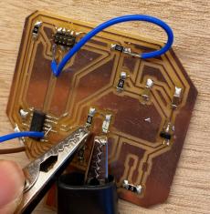
I took the board that I have made two weeks before, and that was not working.
With my instructor we checked again the traces and one was missing:
With my teamates Antonio and Theo we were looking the problem the board could have. They find out that the resistor I put (1000 Ohm) was too big for the LEDs, so Theo changed it for a 100 Ohm resistor.
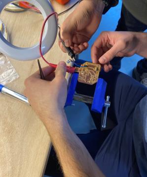
Then we were looking with my instructor the circuit and he add a wire on the first board to make the link that miss between the traces.
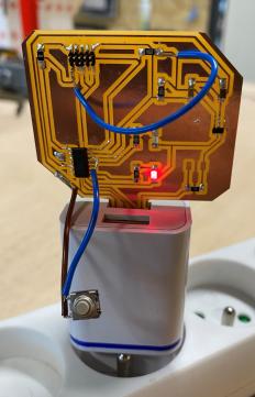
He relaunch the bootloader and because I already have flashed the board, one of the LED was blinking.
I took again the board that I made with the good traces for the button. I desoldered all the resistor that cause problem with the LEDS. I replace the two 1k Ohm resistors by 100 OHM. Then I flashed the bootloader on this board, and then I flashed it with the blinking code on Arduino and it was good.
The Arduino software is now able to see the board connected to an USB port.
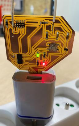
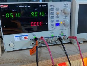
The two LEDs were blinking according to the code. I plugged it to a power source, not to my computer. The board has been flashed and the programm is still inside the microcontroller.
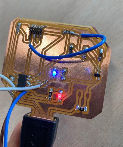
Then the second board, the one with the button with wires. I flashed the bootloader, and flashed the blinking but here, only one LED was working while I flashed the same code. Because this board was manipulate a lot, I was wondering is the LED was burnt. I checked the if the LED is working in putting 3.3V on it.
I desoldered it, and the resistor too, to put them as the same way as the board that is working. I soldered a new LED, but it is still not working. I took a blue LED and checked the datasheet if the resistor is still good for the LED.

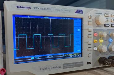
With my instructor we checked with the oscilloscope if current flow through the pin on the microcontroller.
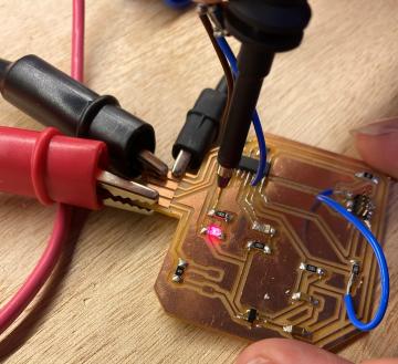
First we checked on the trace where the LED is working, there is signal with squares.
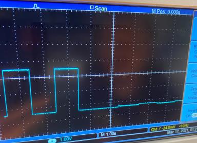
And then when we change to the traces where the LED is not working there is a very poor signal compare to the previous one.
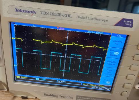
Then we took the two outputs of the oscilloscope to be able to compare the two signal.
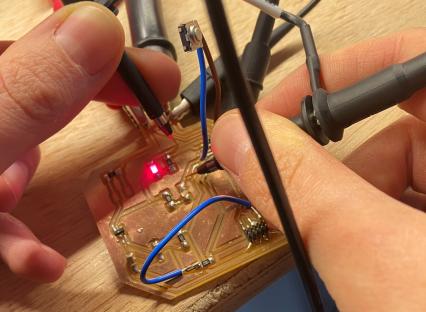
Here we can clearly see that the signal that goes out the pins have problem.
Because this board was manipulate a lot, some parts of the microcontroller might be burn. We need to try to put some wires on another pin to make it working and cut the trace that don’t work.
Programming of SAMD11C - Code
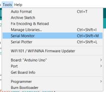
For this week I programmed my board with LEDs and a button. First to learn how to program, I learnt on an Arduino board, with Serial monitor, to learn how to make function, and fill the paragraph on Arduino software. The programmation of this microcontroller is the first microcontroller programmed for the group assignment.
I will put the files of the most advanced programmed I made, because some codes I worte are the step by step I learnt how to code but doesn’t really do much things.
Here is the kind of basic code I wrote.
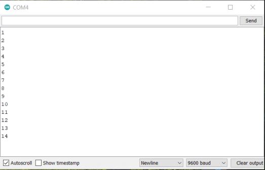
I wrote a code to have a counter print on a serial monitor, to try the tool offer by Arduino. Here I just learnt how to fill the setup and the loop function.
void setup (){
  // put your setup code here, to run once:
  Serial.begin(9600); //speed of communication, 9600 baud, mandatory for the serial monitor to work
  delay(1000); //wait a bit at the beginning
  Serial.printIn("start"); //check if the serial monitor is working
}

int toto = 0; //the counter, an integer

void loop(){
  // put your main code here, to run repeatedly:
  delay(1000); //wait 1 sec, to repeat the loop after
  Serial.printIn(toto); //print the coundter
  toto = toto + 1; //every 1 second, the counter is added of 1
}
This is a screenshot of the serial monitor, where the number of the counter is print.
Arduino website has all the references, function we can use to programm.
During the learning of how to code, I make a mistake in my code. I declared a variable 2 times in the code.
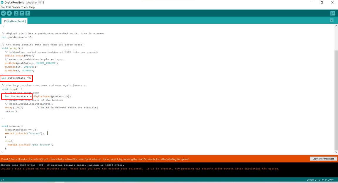
And when I upload the code, it broked the board. I wasn’t able to connect the board to my computer. So I had to reflashed it with the bootloader and the programmer.
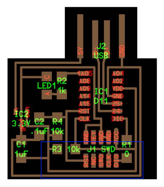
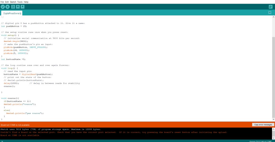
So now, this is the code I wrote to make the green LED on when I push the button, and switch on the red LED when the button is not pushed. I found the number of the pin on the datasheet, mixed with a picture for the name to put on the code, bellow on this website it is explained.
Don’t forget to open the serial monitor at the beginning.
Here I wrote the code in C++ language, using different functions and variables.
int toto = 0; //a integer variable, a counter
int totoref = 0; // a variable that will help to storage the value of my counter and after do comparison
int pinLEDvert = 14; //LED green linked to the pin 14
int pinLEDrouge = 5; //LED red linked to pin 5

int pushButton = 15; //button linked in pin 15

void setup(){
  Serial.begin(9600); //the initial beginning for the serial monitor to be able to work.
  pinMode(pushButton, INPUT_PULLUP); //setup the button
  pinMode(pinLEDvert, OUTPUT); //setup the LED
  digitalWrite(pinLEDvert, HIGH); //check if the LED is working and if we go well in the function
  delay(1000); //wait 1 sec
  digitalWrite(pinLEDvert, LOW); //switch off the LED
  pinMode(pinLEDrouge, OUTPUT); //setup the red LED, and do the same as the LED before
  digitalWrite(pinLEDrouge, HIGH);
  delay(1000);
  digitalWrite(pinLEDrouge, LOW);
}

bool greenLEDstatus = false; //create a boolean

void loop(){
  int buttonState = digitalRead(pushButton); //a variable that will have the state of the button, and help to do some checking in a if loop
  delay(300);
  if(buttonState == 0){ //if the button is pushed, then toto will change, 1 will be added on the variable integer
    toto = toto+1;
  }
  if(totoref != toto){ //if the reference of toto is different of toto, means taht the button has been pushed, the green LED will be on
    Serial.println(toto); //a check if toto has been changed, on the serial monitor
    setLEDvert(true); // check the function below, turn on the green LED
    greenLEDstatus = true;
    setLEDrouge(false); //turn off the red LED
    totoref = toto; //equalize the two variable, to go out from the if
    delay(300);
  }
  else{ //else turn off the green LED, and turn on the red LED, the button has not been pushed
  setLEDvert(false);
  greenLEDstatus = false;
  setLEDrouge(true);
  }
}

void setLEDrouge(bool on_offr){ //same as the next function but for the red LED
  if (on_offr == 1){
    digitalWrite(pinLEDrouge, HIGH);
    //Serial.print("LED rouge ");
    //Serial.println(on_offr);
  }
  else{
    digitalWrite(pinLEDrouge, LOW);
  }

}

void setLEDvert(bool on_offv){ //a function that will turn on or off the LED
  if (on_offv == 1){ //if the boolean is true then the LED will turn on otherwise it will turn off the green LED
    digitalWrite(pinLEDvert, HIGH);
  //Serial.print("LED vert ");
  //Serial.println(on_offv);
  }
  else{
    digitalWrite(pinLEDvert, LOW);
  }

}
The file is available at the end of the page, in all the files.
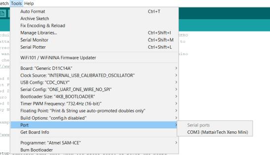
To upload the code on the board with Arduino, first I selected the right board, and not forget to select the port where the Mattairtech board is plugged. And it is the LEDs turned on and off according to the push button.
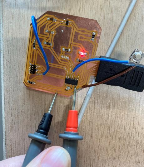
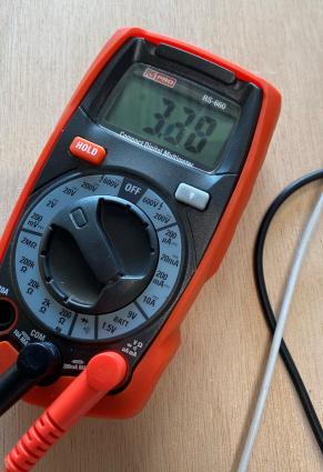
Now because I had issues on one pin on one of my board, I fixed it this week. I change with a wire where the LED is linked on the microcontroller. To check which pin is working, I upload this code in the board, and checked how many volts going out the pin I programmed with the multimeter. I took the basic example on Arduino software and just changed some part to be able to change the number pf the pin quickly.
I won’t put the file of this code, it was taken in the example folder of Arduino, a basic blink, I just added 2 variables to be able to do my checks quickly.
int pinLEDvert = 4; //create a varible of which pin is linked to the LED, to change it quickly and make a test on each pin of the board
int pinLEDrouge = 5; // the red LED is working, and linked to the pin 5

void setup() {
  // put your setup code here, to run once:
  pinMode(pinLEDvert, OUTPUT);
  pinMode(pinLEDrouge, OUTPUT);
}

void loop() {
  // put your main code here, to run repeatedly:
  digitalWrite(pinLEDvert, HIGH); //turn on both LED
  digitalWrite(pinLEDrouge, HIGH);
  delay(1000);
  digitalWrite(pinLEDvert, LOW); //turn off both LED
  digitalWrite(pinLEDrouge, LOW);
  delay(1000);
}
It shows around 3.3 V on the multimeter so I supposed that the pin is working.
I soldered a wire, and cut the trace where the LED is linked with the microcontroller, and when I plugged the board the LED were blinking both, so it worked.
Visual Studio Code
I wanted to work on another IDE. I download Visual Studio Code and add the platformio extension. I checked on the website how to add extension but it didn’t work during the installation.
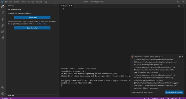
It refers to a website to correct the issues.
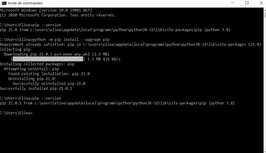
I tried to update pip I installed for my website during the first week.
Here I received the help of my instructor to install platformio on VSC (Visual Studio Code).
First we created a .platformio folder in the root of C: as it is said on the website and restart VSCode but it didn’t work.
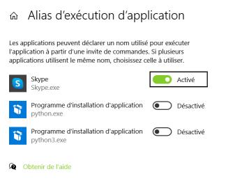
Then we went to App Execution Aliases, disable Python and Python3, and we restart VSCode as administrator, and here it worked.
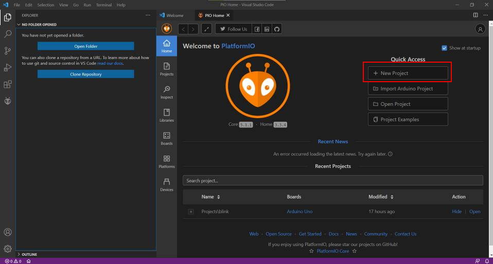
Here is the window when I open VSCode. I created a new project.
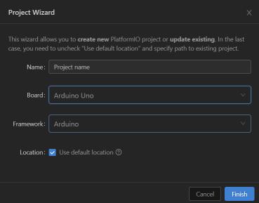
Then I selected the board, the Arduino Uno.
And then it created many files. I write the code on src > main.cpp. The software include already the Arduino library and i just have to write the code.
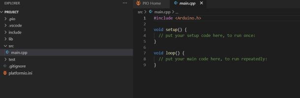
When it is finished I just clicked on the arrow, and it directly upload the code on the board.
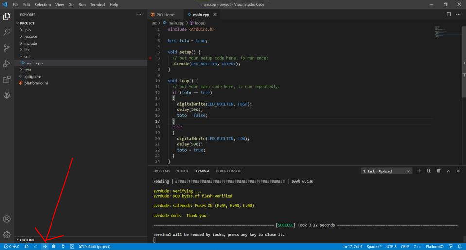
Here is the code.
#include <Arduino.h>

bool toto = true; //a boolean variable to switch between on the LED and off the LED

void setup() {
  // put your setup code here, to run once:
  pinMode(LED_BUILTIN, OUTPUT);
}

void loop() {
  // put your main code here, to run repeatedly:
  if (toto == true) //test the boolean
  {
    digitalWrite(LED_BUILTIN, HIGH); //switch on the LED
    delay(500); //wait
    toto = false; //take the other state
  }
  else //the other case
  {
    digitalWrite(LED_BUILTIN, LOW); //switch off the LED
    delay(500);
    toto = true;
  }
}
What I liked on VSCode is the autocomplete which I don’t have on Arduino software. And also it find the board automatically. One of the problem I have is that I did not find for samd11c the board I want.
Flashing with edbg
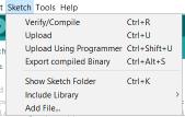
With Arduino software I can also work in exporting the .bin file and work with edbg, that I previously use during the electronics production week.
To do that I need to plug my programmer to my computer, and plug the programmer to the SAMD11C board. The board has to be powered that is why I also plugged it to my computer. On Arduino software I extracted the compiled binary file.
And it appears in the folder where the code is saved.
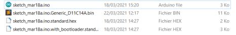
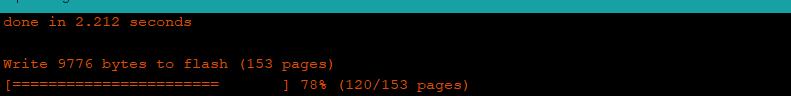
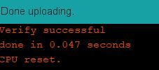
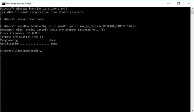
Now I just have to put the .bin file where the edbg file is save, and write the command line. (I need to write the command line when I am in the folder)
edbg -b -t samd11 -pv -f sketch_mar18a.ino.Generic_D11C14A.bin
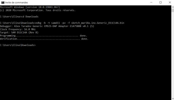
But finally it did not work, and I still do not know how to fix it or what is going wrong.
Reading the datasheet of SAMD11C
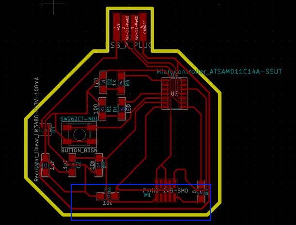
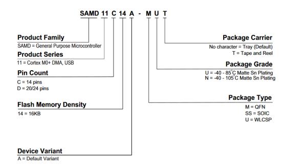
I choose to read the datasheet of the microcontrollers SAMD11 because I use the microcontroller ATSAMD11C14A-SSUTCT-ND on the boards I made.
SAMD11 is a family of micrcontroller, using a 32-bit processor. Ill try to find out what means a 32-bit processor.
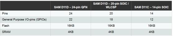
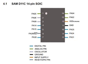
So the microcontroller I took has 14 pins, in package type SS, that means that is a surface component. Then we have the range of temperature the microcontroller can be use, from -40 to 85°C. There is other kind of SAMD11 microcontroller that depends on many parameters.
The SAMD11 has a 16 KB for flash, and 4KB for SRAM. When I flashed the microcontroller, the bootloader was 4KB, so it means that it remains 12KB to flash the microcontroller with a code.
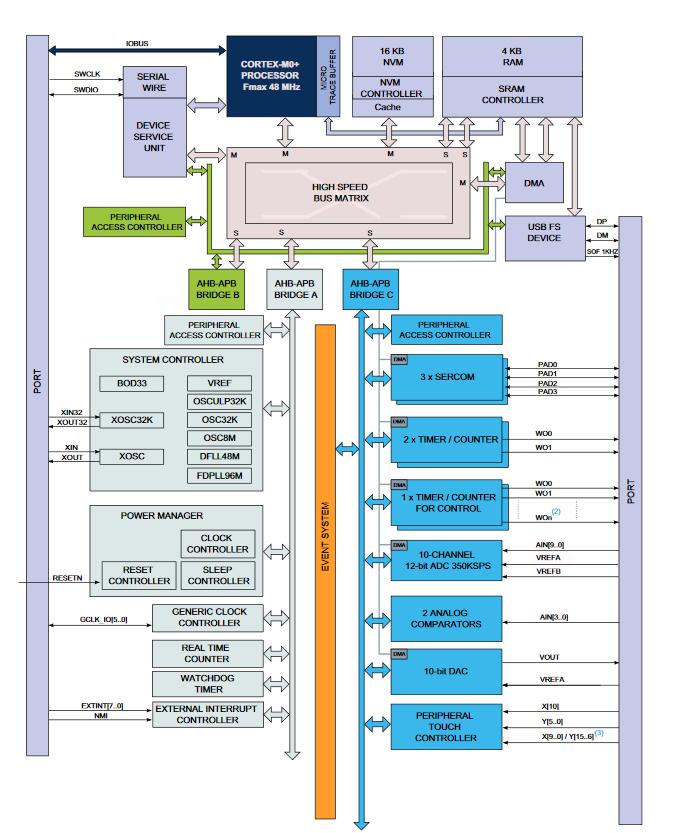
Here is is the general diagram of how the microcontroller is working. I will try to figure out some part of this diagram later on the datasheet.
This schema is very useful first to know on which side put the micrcontroller, according to the white dot, and also to know which pin goes to what. I already use this schema before to know also the name on which pin helped to this documentation
====================================== ATsamD11C14A =====================================
Other  COM   PWM  Analog  INT  Arduino*           Arduino*  INT  Analog  PWM   COM  Other
=========================================================================================
                                  1-------------------
  SCK*/RX2  TCC01    *     *    5 | A5             A4 | 4    *    *  TCC00 MOSI*/TX2  REF
    MOSI*   TCC02          *    8 | A8 (XIN)       A2 | 2    *    *                   DAC
    SCK*    TCC03          *    9 | A9 (XOUT)     Vdd |
  SDA/MISO*  TC10    *    NMI  14 | A14           Gnd |
   SCL/SS*   TC11    *     *   15 | A15           A25 | 25                    USB/DP
BOOT                           28 | A28/RST       A24 | 24                    USB/DM
SWDCLK  TX1/MISO*              30 | A30           A31 | 31   *            RX1/SS*   SWDIO
                                   -------------------

* Most pins can be used for more than one function. When using PIN_MAP_STANDARD, the port
  pin number printed on the chip above is also used in Arduino (but without the 'A') for
  all of the supported functions (ie: digitalRead(), analogRead(), analogWrite(), etc.).
  When using PIN_MAP_COMPACT, the Arduino numbering is sequential starting from 0 at the
  top left pin (A5). PIN_MAP_COMPACT uses less FLASH.
* When USB CDC is enabled, Serial refers to SerialUSB, otherwise it refers to Serial1.
* When using ONE_UART_NO_WIRE_ONE_SPI, use SPI on pins 4, 5, 14, and 15.
  When using NO_UART_ONE_WIRE_ONE_SPI, use SPI on pins 8, 9, 30, and 31.
* Tone available on TC2. TC2 is not routed to pins in the D11C14A.
* Leave pin A30 floating (or use external pullup) during reset.
* DO NOT connect voltages higher than 3.3V!
There is two kind of signal, Analog or Digital. An analog signal is like a sinosoïdal curve, it can take an infinity amount of value, here for example with this kind of microcontroller, from 0V to around 3.3V. The digital signal is kind of transform this signal into a value, for example for 32 bit, it can take 2 to the power of 32 number of values, increment. For a 8 bit it can take 256 (2 to the power of 8) values, from 0 to 255 if it is unsigned or -127 to 128 if the values are signed.
The power supply is given from the VDD pin and goes out to ground - GND. It is distribute to the different pin and goes through some regulator.
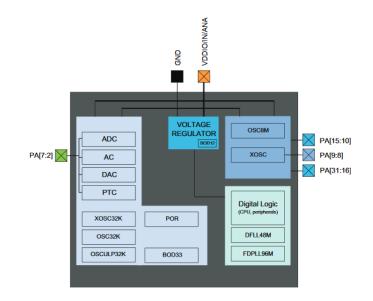
Inside the microcontroller there is a map for the memory, like in the real life, postal adress. Some adress are already taken, reserved and some are ready to be written on it. The informations are flying through a BUS system, that distribute the informations.
The High-Speed Bus system is working with a clock. It is some 32 bit data bus, that mean that can handle pretty big informations.
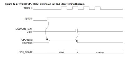
There is a Device Service Unit (DSU). When my board was bricked, on week 7, we used this system with my instructor to debrick it, by forcing the rest to the ground with a wire and be able to flash again the microcontroller.
There is a clock system inside the microntroller. I tried to understand how this system work. The clock system works at some frequence in MHz, 8 MHz if the oscillator OSC8M is used. Clock system can be synchronize or not synchronize. I think it how fast the informations can go inside the microcontroller, with kind of each “top” a BUS is send.
On the PIN schema there is the Analog pin, or Digital pin. There is an ADC, Analog to Digital Converter.
Group assignment
For the group assignment, I compare the caracteristic of the micrcontroller used on Arduino Uno board, the ATmega328P (one datasheet). The informations of the microcontroller on the board Arduino Uno are available on the Arduino website, on tech specs.
Here is the comparison between the SAMD11C, the ATmega 328P and the Broadcom BCM2837.
| Configuration Summary | SAMD11C-14 pin SOIC | Arduino Uno - ATmega328P | Rasberry Pi 3 - Broadcom BCM2837 |
|---|---|---|---|
| Number of pins | 14 | 28 | 40 |
| Number of I/O pins | 12 | 14 Digital I/O Pins; 6 PWM Digital I/O Pins; 6 Analog Input Pins | 40 |
| Flash memory | 16 KB | 32 KB where 0.5 KB are taken by the bootloader | 1GB |
| SRAM | 4 KB | 2 KB | N/A |
| Clock Speed | 16 MHz | 900 MHz * 4 Cores | |
| Time counter (TC) | 2 | N/A | |
| Output channels for TC | 2 | 40 | |
| Timer Counter for Control (TCC) | 1 | N/A | |
| Output channels per TCC | 8 | N/A | |
| Direct memory access channels | 6 | N/A | |
| USB interface | Yes | YES | |
| Serial Communication Interface (SERCOM) | 2 | 2 | |
| Analog-to-Digital Converter (ADC) channels | 5 | N/A | |
| Analog Comparators (AC) | 2 | N/A | |
| Digital-to-Analog Converter (DAC) channels | 1 | N/A | |
| Real-Time Counter (RTC) | Yes | YES | |
| RTC Alarms | 1 | 1 | |
| RTC compare values | 1 32-bit value or 2 16-bit values | N/A | |
| External Interrut Lines | 8 | N/A | |
| Peripheral Touch Controller (PTC) channels for mutual capacitance | 12 (4x3) | N/A | |
| Peripheral Touch Controller (PTC) channels for self capacitance | 7 | N/A | |
| Maximum CPU frequency | 48MHz | 1.2 GHz *4 Cores | |
| Packages | SOIC | 28P3 | Board SoC |
| Oscillators | 32.768kHz crystal oscillator (XOSC32K) 0.4-32MHz crystal oscillator (XOSC) 32.768kHzinternal oscillator (OSC32K)32kHz ultra-low-power internal oscillator (OSCULP32K) 8MHz high-accuracy internal oscillator (OSC8M) 48MHz Digital Frequency Locked Loop (DFLL48M) 96MHz Fractional Digital Phased Locked Loop (FDPLL96M) | N/A | |
| Event System channels | 6 | N/A | |
| SW Debug Interface | Yes | N/A | |
| Watchdog Timer (WDT) | Yes | N/A | |
| Temperature range | -40 to 85°C | -40°C to 85°C | -40 to 85 C |
| Operating voltage | 1,62 to 3,63 V | 1.8 to 5.5 V | 5.1 V |
| Processor | ARM Cortex-M0+ CPU running at up to 48MHz | BCM2837 Broadcom system on chip |
Micro:bit - programming microcontroller Nordic nRF51822
During the bootcamp week, I discovered a little bit about micro:bit, that’s why I reused this board for this week. On micro:bit website, there is an interface, makecode editor to play with code as blocks. I made the programm with blockly language, that bring to a JavaScript code. The micro:bit board is processed by a MCU Nordic nRF51822.
The programmation of this microcontroller is the second microcontroller programmed for the group assignment.
To test the editor, I put the blocks to make the board print “hello” at the end and when we push the A button, it make a heart shape blink two times. The button B clear the LEDs.
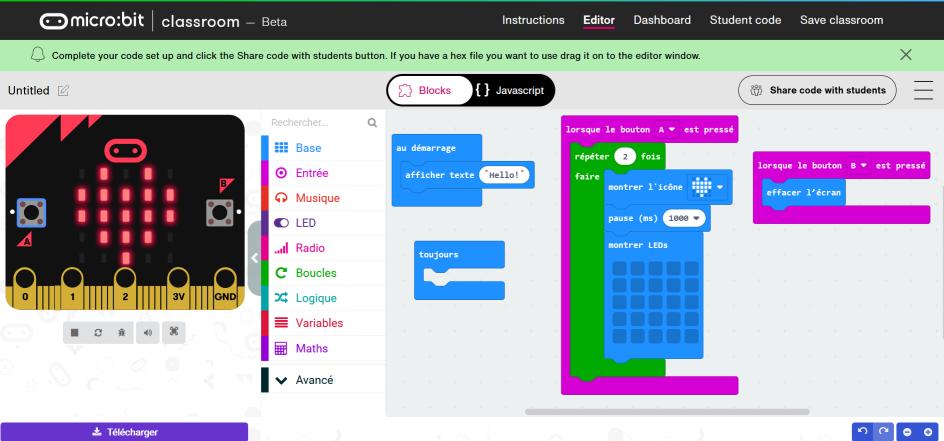
We can also check the code in JavaScript:
input.onButtonPressed(Button.A, function () {
    for (let index = 0; index < 2; index++) {
        basic.showIcon(IconNames.Heart)
        basic.pause(1000)
        basic.showLeds(`
            . . . . .
            . . . . .
            . . . . .
            . . . . .
            . . . . .
            `)
    }
})
input.onButtonPressed(Button.B, function () {
    basic.clearScreen()
})
basic.showString("Hello!")
basic.forever(function () {

})
I did not write the code in JavaScript, but I just checked to know what is going on in with this language and blockly I used.
When the code is done, I just need to download the file and then copy it in the micro:bit board, plugged to my computer.
And here is the result:
This way of working is nice to learn quickly some code, and very nice to see, but it is pretty limited, to the micro:bit board.
Resize video with ffmpeg
This week I add a small video on my website. First the video I recorded had a size of 3.91 Mo. To add it on the website I have to make it smaller, so I looked on Kris did during the bootcamp (at around 1:33:00) with his tutorial. And I tried on my computer but it didn’t work because I put a random value for the size of the video (scale=”100:-1”).
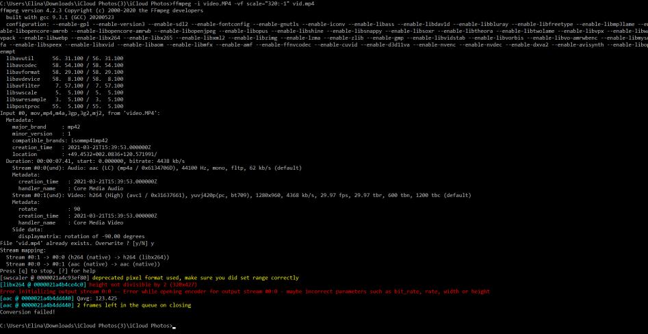
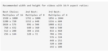
After looking on internet forums, I discovered here that a size of a video have rules to respect.
And then I sized well my video and it worked.
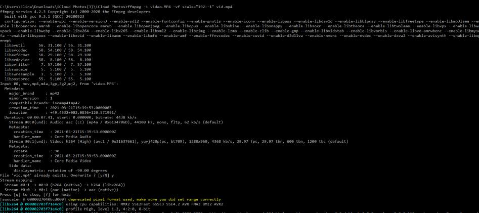
ffmpeg -i video.MP4 -vf scale="192:-1" vid.mp4
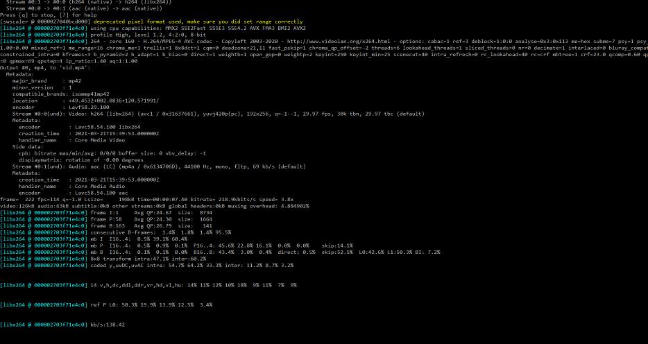
The video is only 197 Ko now.
Here is the code is used to add it on my internet website.
<video controls="true" allowfullscrenn="true" width="35%">
  <source src="../../images/week09/vid.mp4" type="video/mp4">
</video>
All the files
- The folder of the code switch LED with button
- The folder of the code in Visual Studio Code
- Micro:bit file, heart blink