5. Electronics production
This week we made an in-circuit programmer. Here are the different steps taken to arrive at the final product
Assignement
Group assignement : Characterize the design rules for your PCB production process
Individual assignment : Make an in-circuit programmer by milling and stuffing the PCB, test it, then optionally try other PCB processes
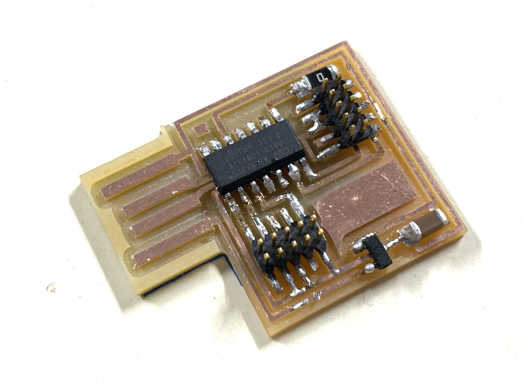
Hero shot
Workflow
- Find and save a png image of your traces and outline
- Open mods
- set up your file and save it
- Move this file to the local server
- Start the machine by pressing the on/off button on the top right for 3 seconds.
- Turn on the computer and open Vpanel.
- Positioning and fixing your copper plate to be machined correctly
- Install the corresponding bit
- Carry out the 0’s on the X, Y and Z axes.
- Find and import your file in Vpanel
- Launch the production of your board.
Group assignement
The device
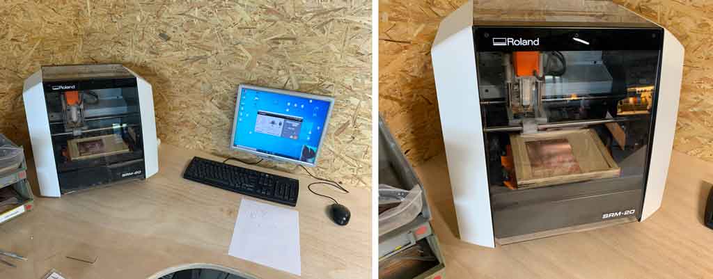
The Roland SRM-20 portable milling machine is capable of milling a wide range of materials, including modelling wax, composite wood, foam, acrylic, polyacetate, PCB boards.
Vpanel software
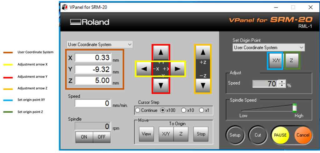
The roland SRM20 CNC is controlled using Vpanel software. This software enables dialogue between the machine and the computer. With this software it is possible to adjust the settings of the machine, the coordinates of the X, Y and Z axes, but also to import a file for subsequent machining. The VPanel controller of the SRM-20 provides a simple interface for adjusting the tool position and moving the cursor to set the milling origin point. VPanel also provides easy control of travel speed and spindle speed, with a pause/resume function, and monitoring of milling in the X, Y, and Z axes using digital indicators in millimeters or inches.

Characteristic table of the machine
| Template | SRM20 |
|---|---|
| Machinable materials | Acrylic resin, wood composite, modelling wax, PCB FR1 board |
| Distance between tool collet and table | 130.75 mm max. |
| Distance in X, Y and Z | 203,2 x 152,4 x 60,5 mm |
| Table size | 232,2 x 156,6 mm |
| Machining speed | 6 to 1800 mm/min |
| Software resolution | 0.01 mm/step (RML-1), 0.001 mm/step (NC code) |
| Mechanical resolution | 0.000998594 mm/step |
| Maximum spindle rotation | 7 000 rpm |
| Steering Language | RML-1, NC code |
| Power consumption | 55W |
| Dimensions | 451 (L) x 426,6 (D) x 426,2 (H) mm |
| Weight | 19,6 kg |
| Installation environment | Temperature: 5 to 40°C. Humidity: 35 to 80% (non-condensing) |
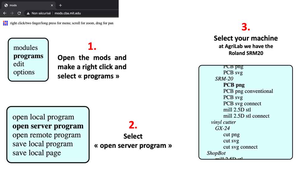
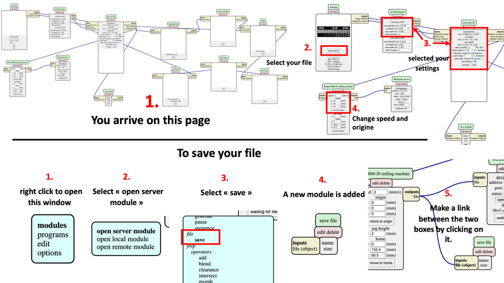
Mods, the steps for uploading a file
Open the mods on your web browser and follow the instructions below.
Your file downloads itself is in your “download” folder. Then simply import it into your software. For us Vpanel.
Results
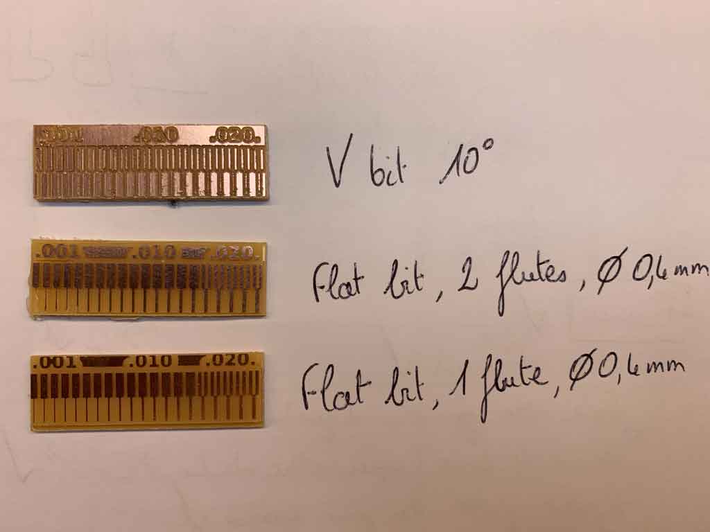
In order to test our machine we have carried out 3 tests with different bits. We tested a V bit 10°, a 0.4 diameter flat bit 2 flutes and a 0.4 diameter flat bit 1 flute. All of our tests were carried out in a climb mode. Finally to cut the board we used a 1 mm drill bit. We can easily see a significant difference between the different bits.
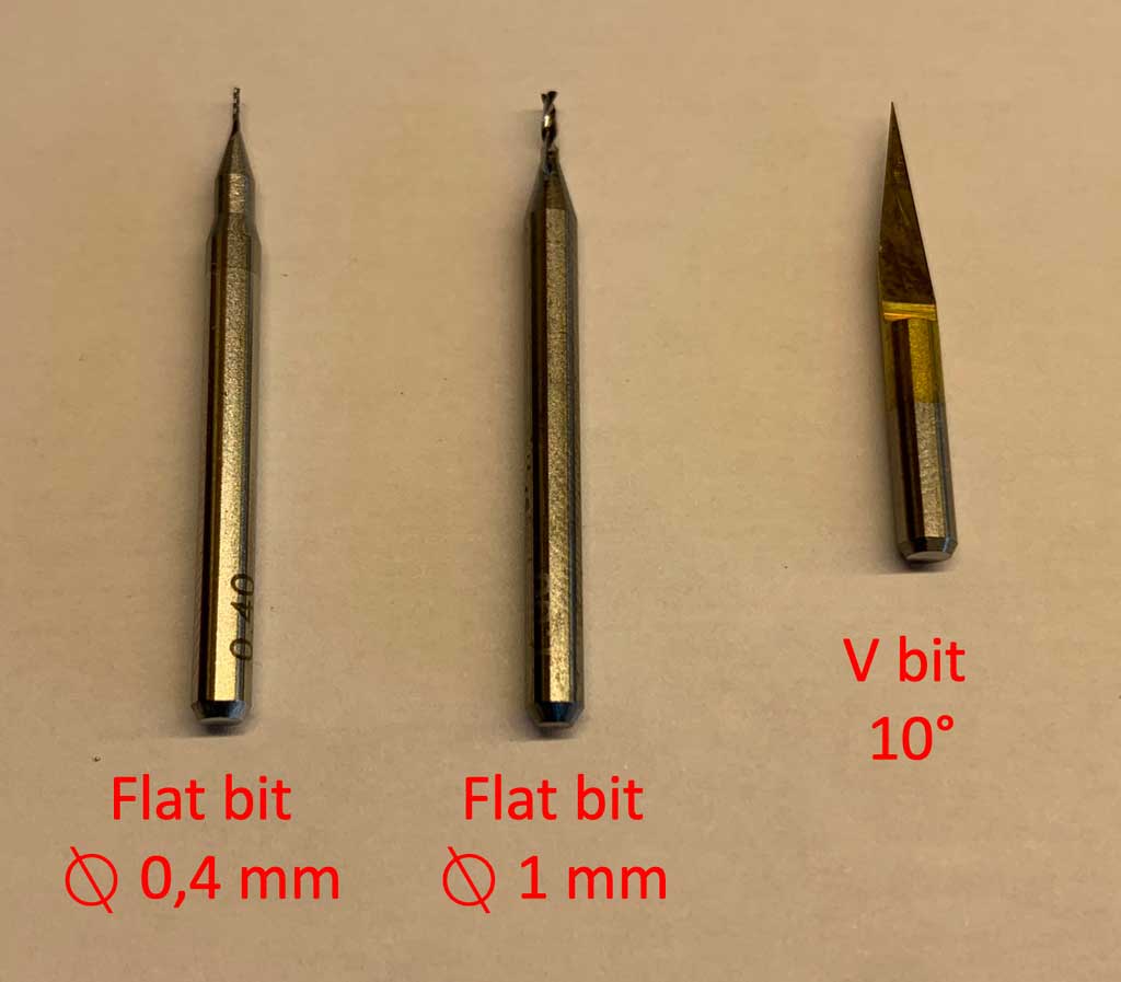
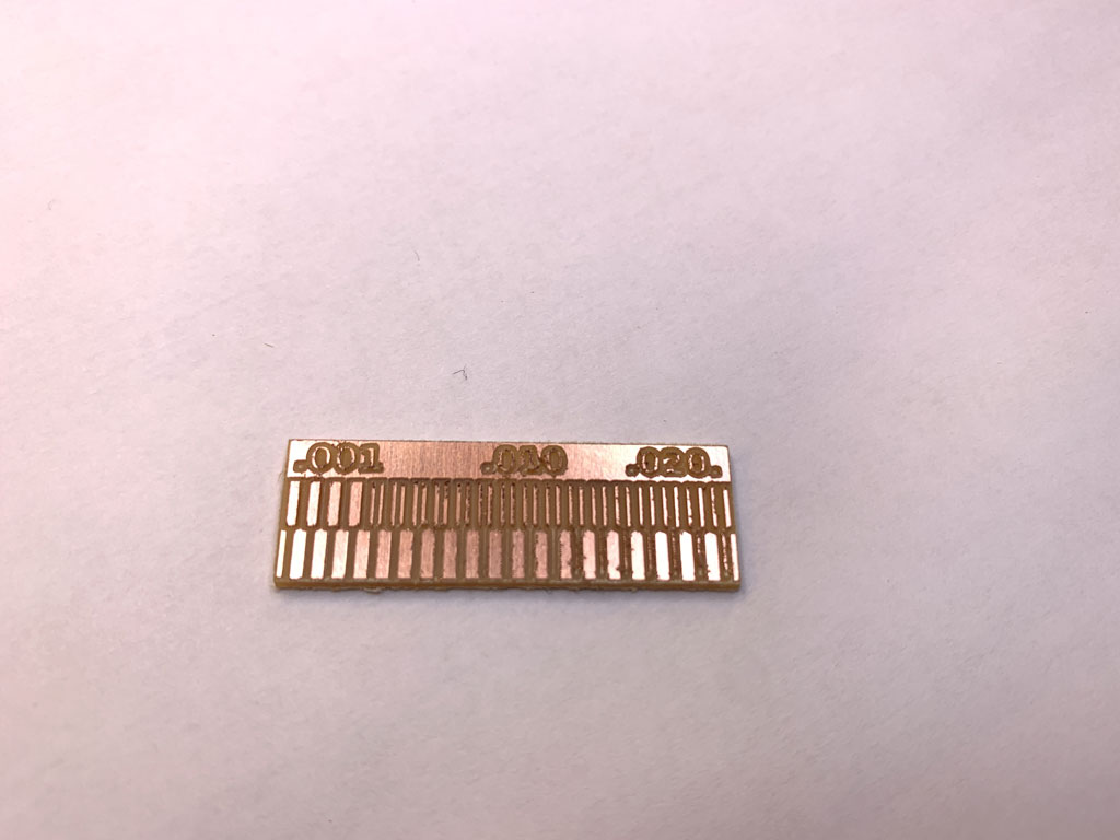
We can see that with the V bit 10° the result is very approximate and the finishes are poor. However we have a precision up to 0.09 mm.
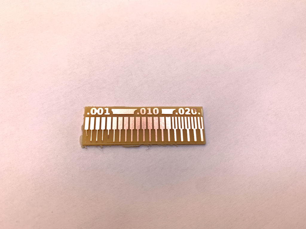
For the 0.4 diameter flat bit 2 flutes, the result seems clean and precise but we can see that the very fine lines (0.001 inch to 0.004 inch) did not withstand the machining, probably due to too much aggressiveness of the bit. Moreover, with a bit of 0.4 mm diameter we cannot go into a part smaller than 0.016 inch (=0.4064mm).
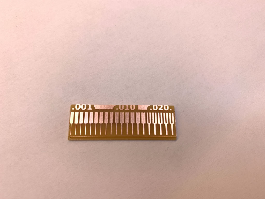
For the 0.4 diameter flat bit 1 flute, the results seem similar to the 0.4 diameter flat bit 2 flutes however it can be seen that this one did not damage the wires from 0.001 to 0.004 inch unlike the other one. This bit can therefore be considered less aggressive and a little more precise.
Individual assignment
I chose the circuit which is called hello.CMSIS-DAP.10.D11C under the advice of my instructors Luc and Florent. They advised us to take this board because it will serve us well in the future.
Mods, the steps for my board
He has the same steps performed as explained above, obviously changing the files. Here are the previews of my files :
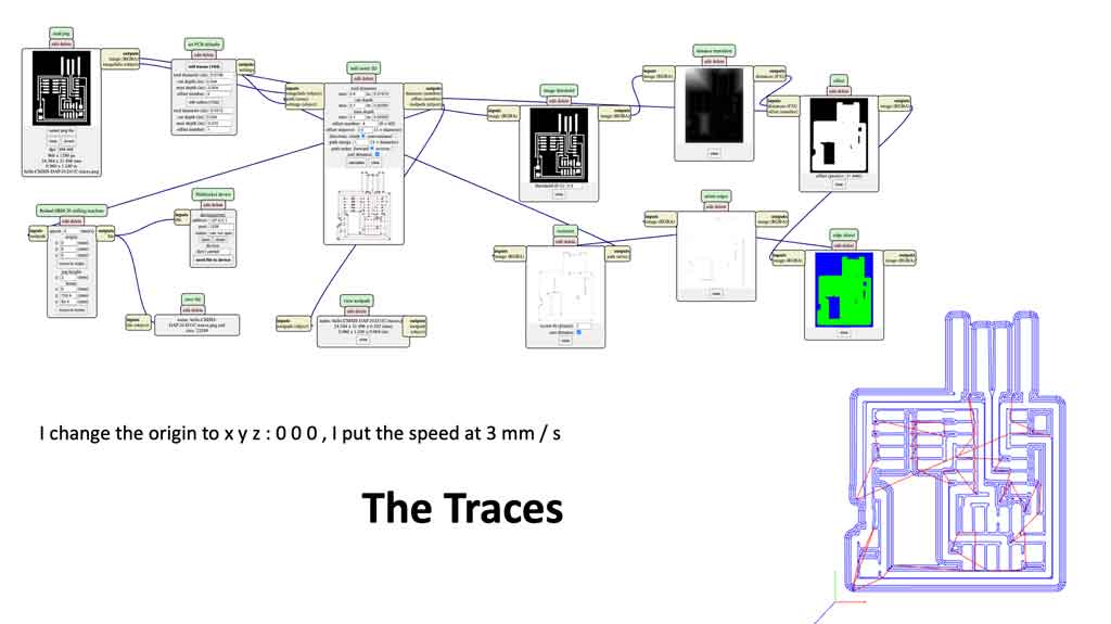
Settings :
- Tool diameter : 0,4 mm
- Cut depth : 0,3 mm
- Max depth : 0,3
- Offset number : 4
- Direction : climb
- Speed : 2,5 mm/s
- Origin
- X : 0
- Y : 0
- Z : 0
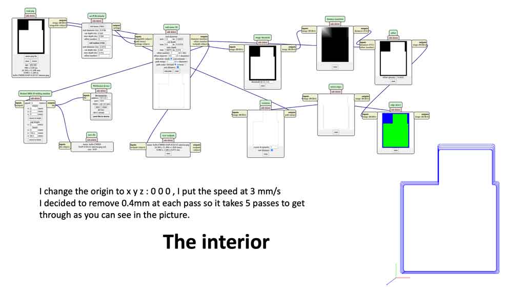
Settings :
- Tool diameter : 1,0 mm
- Cut depth : 0,3 mm
- Max depth : 1,9
- Offset number : 1
- Direction : climb
- Speed : 3 mm/s
- Origin
- X : 0
- Y : 0
- Z : 0
How to fix the board?
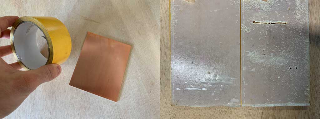
The boards we use at AgriLab are FR1. These boards have a thin layer of copper on top and a thickness of phenolic paper underneath. The advantage of this board is that it is easier to machine, which protects the tools and allows you to go a little faster. Moreover, unlike its counterpart the FR4, the FR1 does not contain any epoxy, which can be dangerous for humans during machining.
The boards have a dimension of 10.2 cm x 15.24 cm. The thickness of the board is 1.6 mm.
To fix the plate on the sacrificial layer we put a layer of double-sided tape on the phenolic part. In order to make it as straight as possible, air bubbles are drilled out. Then we glue the plate firmly to the sacrificial layer.
How to set up the machine correctly ?
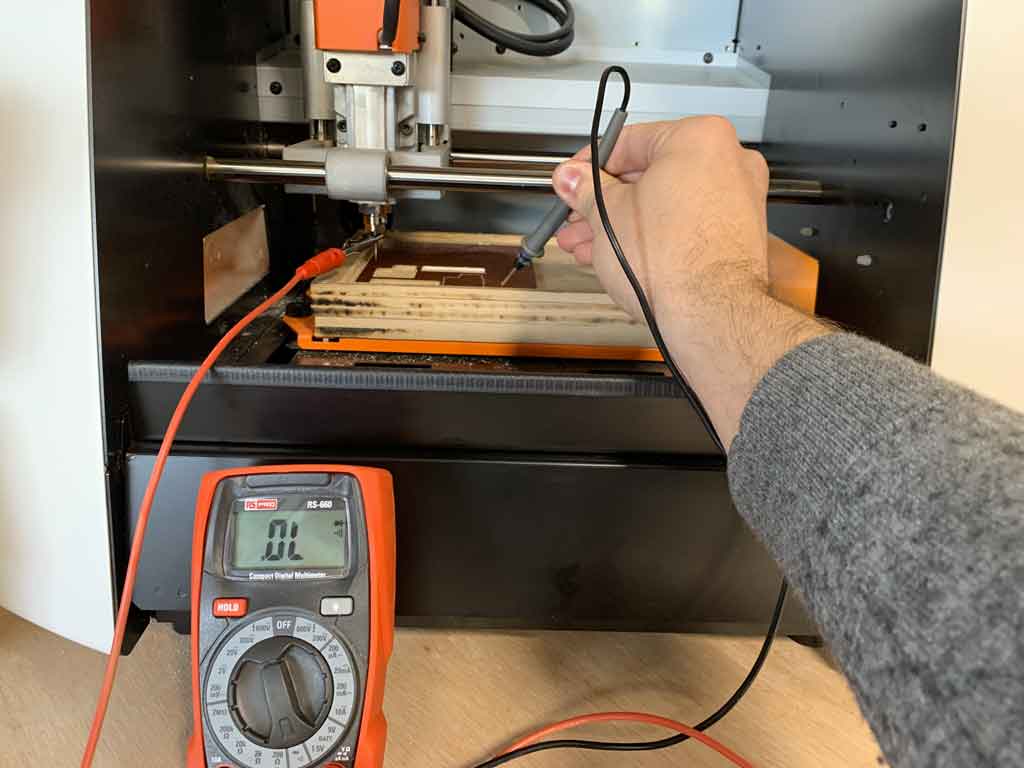
To set up the machine, first of all you need to know the point of origin of the file you wish to use. Once the coordinates are known, set the 0’s on the machine. To do this, start by moving the X and Y arrows. Once the positioning has been determined, press the XY button to determine the 0. Once the 0 XY of validated you can initialize the 0 for the Z. To do this, lower the milling machine using the Z arrow. In order to know exactly if the bit head is in contact with the copper surface, a multimeter must be used. The conductivity function of the device is used for this purpose. Connect one connector to the collar and position the other on the copper surface. The moment the instrument rings is the moment you are in contact. You can therefore initialise your 0 (Z).
When you have made different 0’s you can import your file and launch the procedure.
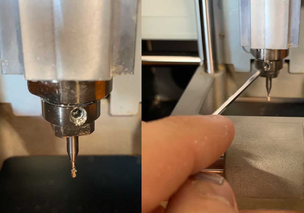
how to change the bits ?
To change the bits simply unscrew the small screw on the collar. Once the screw is loosened, simply remove the bit and place the new one and then tighten the screw again.
Caution: do not forget to redo your 0 on the Z axis!
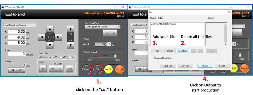
How do I import a file into Vpanel ?
To import a file into Vpanel you need to perform the following steps :
So I imported my files into Vpanel with the traces and contours I needed to make my board.
Here is the result after milling.
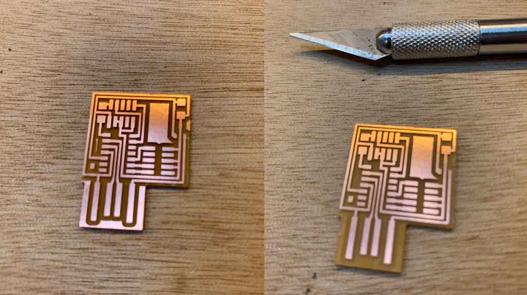
The excess copper on the sides must then be removed to avoid the risk of creating a short circuit when connecting to a computer.
Soldering
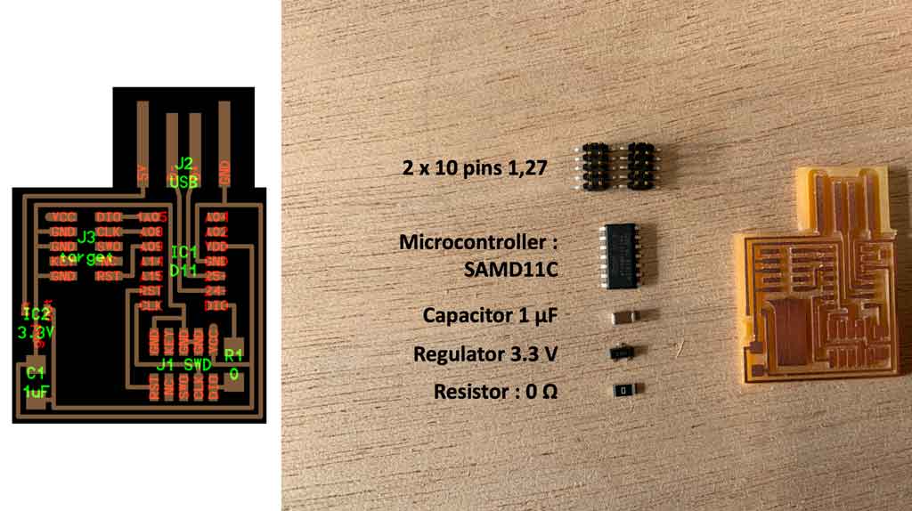
An important step of the week was to soldering the components on the board. For this I put together the following components :
- 1 Board
- 2 x 10 pins 1,27
- 1 microcontroller SAMD11C
- 1 resistor 0 ohm
- 1 capacitor 1 uF
- 1 regulator 3.3 V
In order to help me with the welding I followed the plan that helped us with the board.
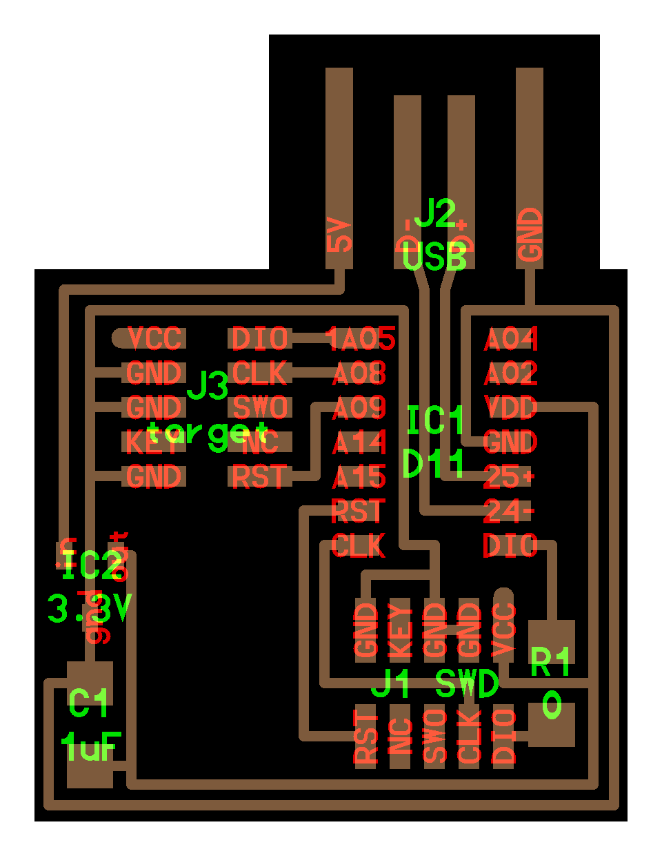
For soldering I decided to start with the microcontroller. It’s easier to start with the middle components and go more and more to the outside of the board. So I then soldered the capacitor and the regulator. Then I soldered the resistor and the pins to finish.
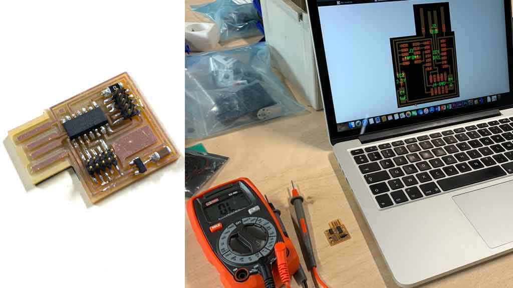
Once finished I tested my board with a multimeter and the continuity function. I used the diagram provided to check if I hadn’t made a mistake or put tin on several tracks. All is good, I can flash it serenely.
Programming
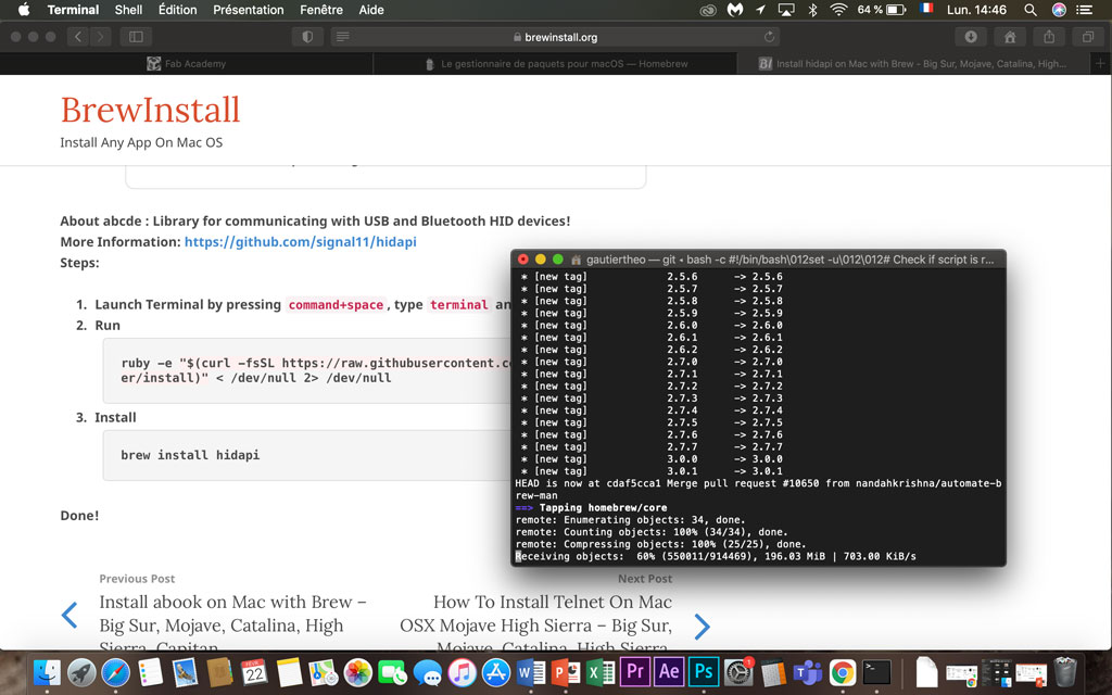
First, I downloaded the necessary files to my computer. I found everything I needed here. So I followed their tutorial. For this I had to download Brew
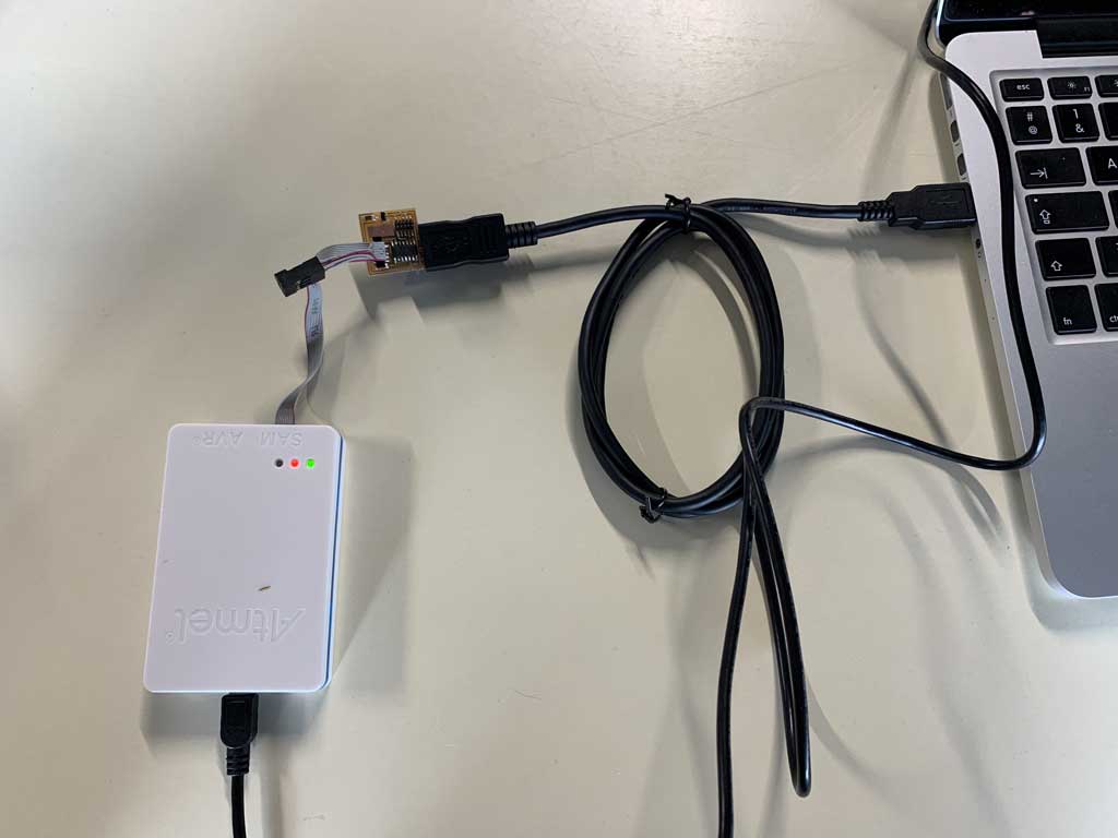
Then you have to connect your board to a programmer and power it up with USB cables like this
Once Brew was installed and my board connected to the programmer and power. I checked if the programmer was recognised by my Mac. To do this, I noted in my terminal:
ls /dev/cu.*
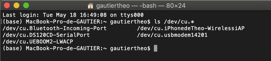
As you can see, the programmer is well recognised by my computer.
/dev/cu.usbmodem14201
This line means that the device is connected to my Mac, in my case the programmer.
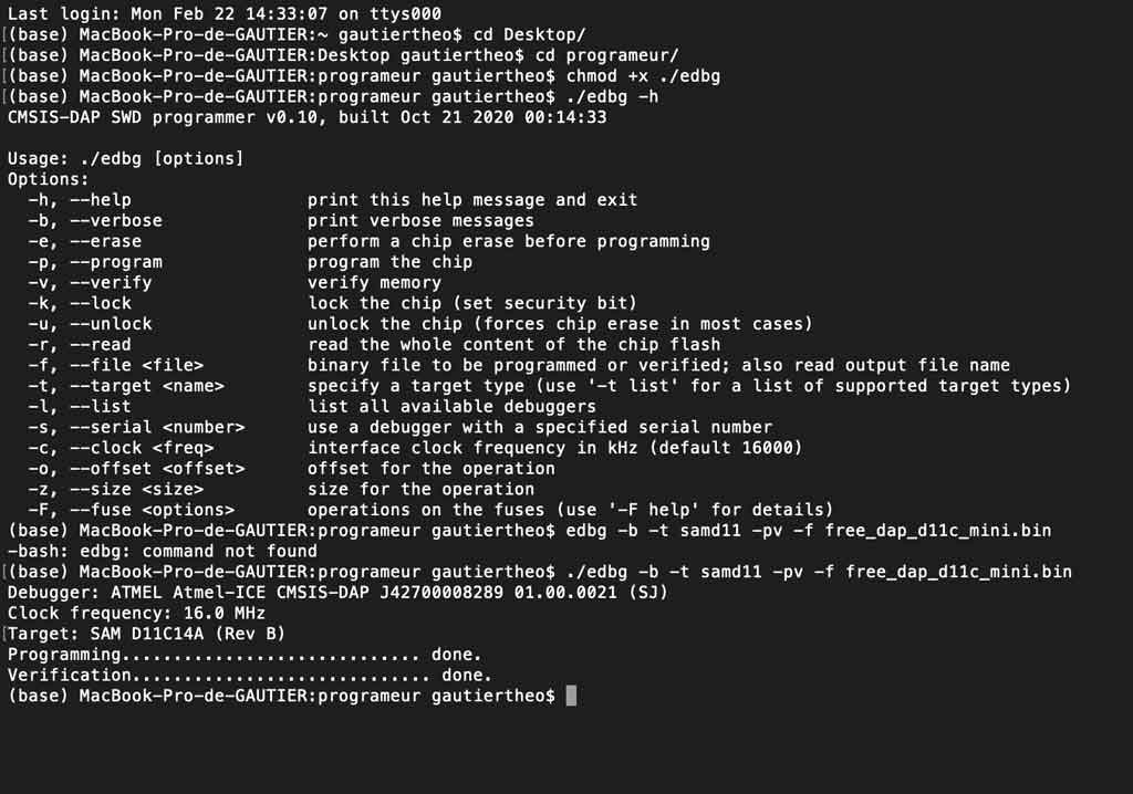
After all these checks I was able to note this line in my terminal to flash my board:
edbg -b -t samd11c -pv -f free_dap_d11c_mini.bin
It worked !
Mistake
I broke a 0.4mm diameter drill bit because the speed I had set was too high. So I reduced the machine’s working speed.
Conclusion
This week allowed me to begin to understand the differences between the electronic components. We learned how to use the CNC to produce our own circuit, it is very interesting to understand the process. I really enjoyed practicing soldering, it allowed us to build something concrete.