6. 3D Scanning and printing
This week we had the chance to learn 3D printing and the scanning of an object thanks to several techniques.
3D printing is a process of manufacturing parts in volume by adding material in successive layers from a 3D model. It is used in many different domains such as prototyping, industry, aeronautics, construction, military, bio-printing or food. 3D printing makes it possible to produce a real object drawn by computer. The 3D file obtained is processed by specific software which organises the cutting into slices of the different layers necessary for the production of the part. The slicing is sent to the 3D printer which deposits or solidifies the material layer by layer until the final part is obtained. The principle remains close to that of a conventional 2D printer with this major difference: it is the stacking of layers that creates the volume.
A three-dimensional scanner is a 3D digitisation and acquisition device. A 3D scanner is a device that analyses objects or their close environment to collect precise information on their shape and possibly on their appearance (colour, texture, etc.). The data thus collected can then be used to build three-dimensional computer-generated images (digital objects) for various purposes. These devices are widely used by the entertainment industries for films or video games.
-
- Test the design rules for your printer(s)
- Document your work and explain what are the limits of your printer(s) (in a group or individually)
-
Individual assignment:
- Design and 3D print an object (small, few cm3, limited by printer time) that could not be easily made subtractively
- 3D scan an object, try to prepare it for printing (and optionally print it)
Group assignment
Description of the machine
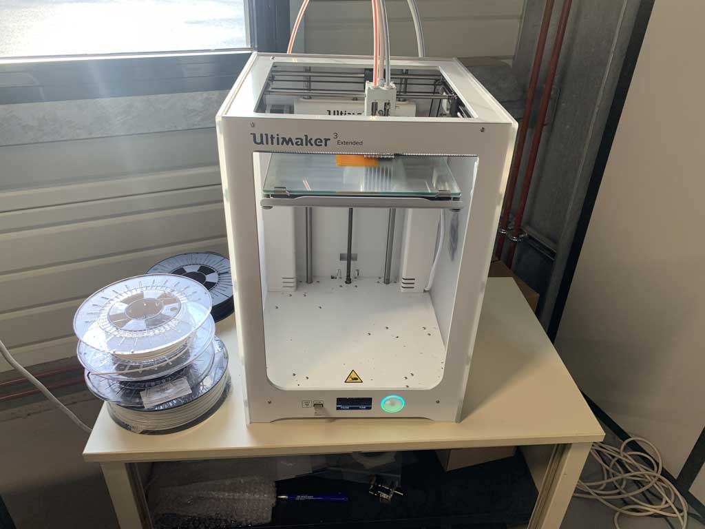
The Ultimaker 3 Extended 3D printer is the large format version of the Ultimaker 3. This allows you to print larger objects. With high printing accuracy and ease of use, it allows complex objects to be printed without too much difficulty. With its PrintCore system, the print heads are interchangeable and adapted to each material. This results in a more homogenous and precise deposit and reduces the risk of nozzle clogging. The double extrusion system allows you to combine printing materials with soluble substrates to create more complex parts. You can also make colour prints.
| Device | |
|---|---|
| Designation | Ultimaker 3 extended |
| Computer interface | USB, Wifi, Ethernet |
| Print head | 2 heads |
| Printing speed | 300 mm/s |
| Print volume | 215 x 215 x 200 mm |
| Consumable materials | ABS, PLA, Nylon, CPE, Polycarbonate, PVA |
| Number of colours | 2 |
| Nozzle diameter | 0,4 mm |
| Max. nozzle temperature | 280°C |
| Max plate temperature | 100°C |
| Filament diameter | 1,75 mm |
| Layer thickness | 20 micron |
| OS accepted | Windows, Mac OS X and Linus |
| Physical characteristic | 688 x 493 x 338 mm |
| Weight | 11,3 kg |
The torture test :
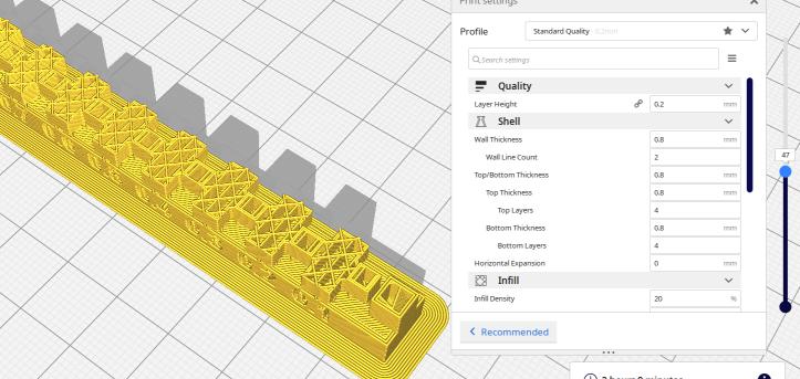
To characterize the machines we decided to use the Cura software to slice our object. This software is open-source and is available for all our OS (yes we are 3 and we have a Windows, a Linux and a Mac). Moreover we agreed on the object to be printed. We found this file on the Internet which we then shared with each other. We also chose to have the same print settings to achieve a good benchmark.
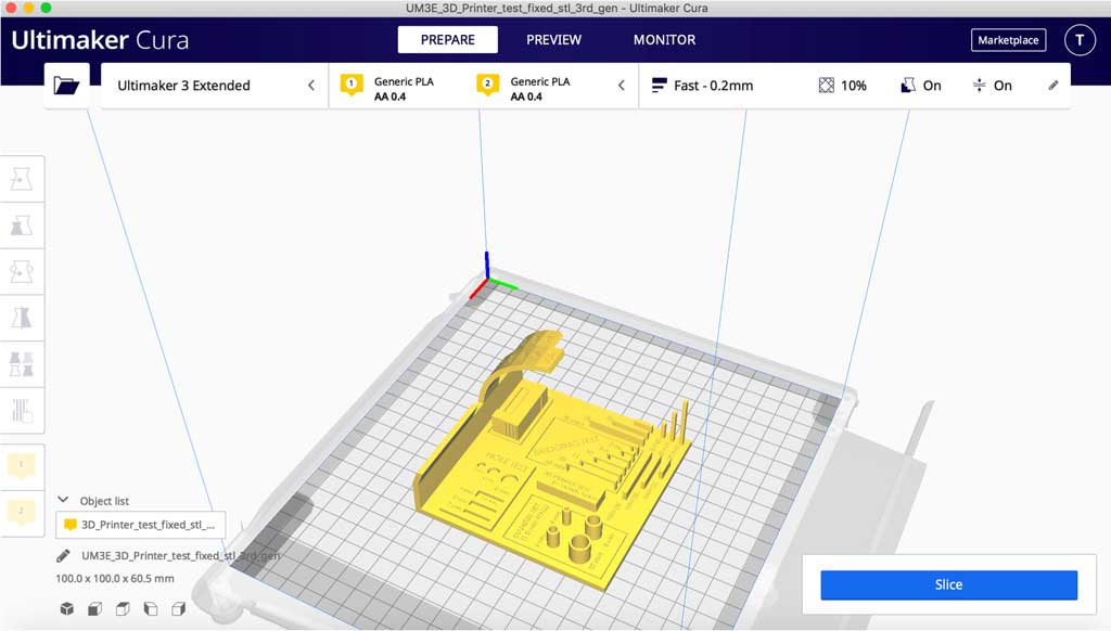
Print settings :
- Material : PLA
- Layer height: 0.2 mm
- Wall Thickness: 0.8 mm
- Nozzle: AA 0.4 mm
- Infill: 20% tri-hexagon
- Printing temp: 205°C
- Bed temp: 60°C
- Print Speed: 70 mm/s
- No support
- Adhesion Platform : Brim
Printing time: 5h 28 min
Results for the Ultimaker 3 extended
| Test | Comments |
|---|---|
| External diameters | 9.8 mm instead of 10 mm, 7.8 mm instead of 8 mm, 5.8 mm instead of 6 mm, 3.8 mm instead of 4 mm |
| Inner hole | 7.5 mm instead of 8 mm, 5.5 mm instead of 6 mm |
| Angles | No more than 45° |
| Bridge | Pitch over 15 mm |
| Corners | All corners are rounded |
| Writing | The writing on the top is not legible because the layers are too high. If we had set the layers to 0.1 mm the writing would have been more visible. |
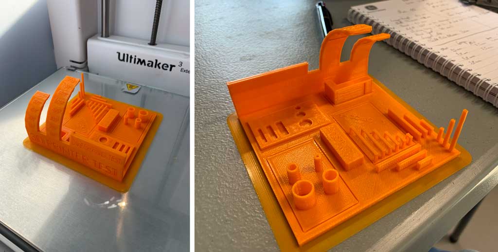
We can see that the Ultimaker 3 Extended is a machine that is quite accurate. We can see an accuracy of 0.2 mm on average for outside diameters. For the inside diameters we can see an inaccuracy of 0.5 mm but this may be due to a measurement error, I couldn’t get the calliper in the hole which was too small. Concerning the angles, we can see that if the angle is greater than 45° then the layers are no longer accurate. A length of more than 15 mm also leads to an inaccuracy of the lower layers which are in the void.
Note: you can see that all right angles are rounded. This is due to the fact that the nozzle sends a round jet. It is therefore impossible to create a right angle with a protruding edge. Of course this is really very small and is equivalent to the diameter of the nozzle, so the right angle is slightly rounded by a few millimetres.
Test designs for Creality ender 5 plus
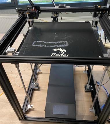
| Device | |
|---|---|
| Designation | Creality ender 5 plus |
| Computer interface | USB |
| Print head | 1 head |
| Print volume | 350 x 350 x 400 mm |
| Consumable materials | ABS, PLA, Nylon, CPE, Polycarbonate, PVA |
| Nozzle diameter | 0,4 mm |
| Max. nozzle temperature | 260°C |
| Max plate temperature | 110°C |
| Filament diameter | 1,75 mm |
| Print accuracy | 0,1mm |
| Physical characteristic | 632 x 666 x 619 mm |
| Weight | 23,8 kg |
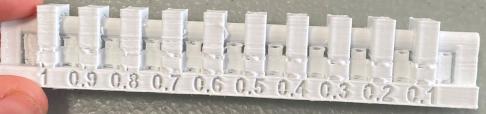
Clearance
First I wanted to do some test to check the gap between 2 shapes that can handle the device to be able to do some jointures. I downloaded a file to test the clearance of the device, available on the fabacademy website. I made all the tests for the Creality ender 5 plus.
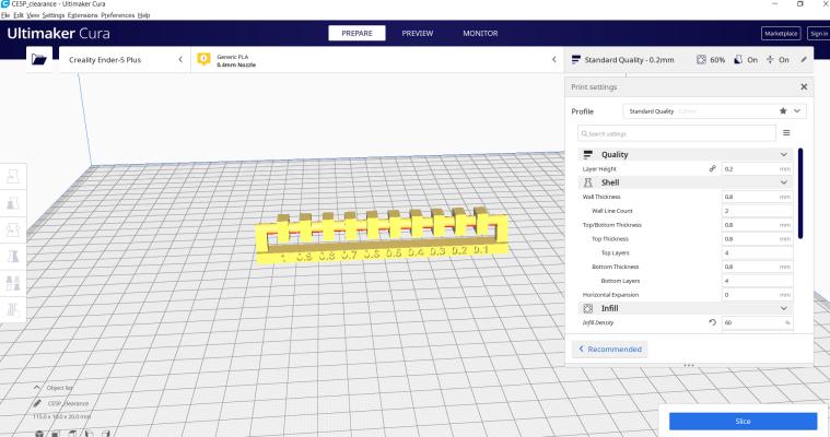
After downloading the .stl file for clearance I clicked and dragged it on the Cura software.
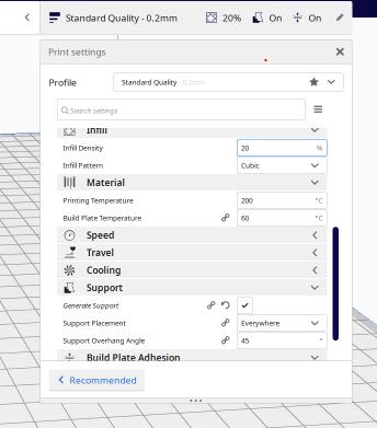
First I chose my printer. I picked the Creality ender 5 plus to make the tests. I set some parameters like adding a brim under the shape, infill the density at 20%, because it wanted to print my test in a few time. I generate a support for the shape because if the printer print in the air I wont get the shape I want.
I checked the temperatures of the plate and the printing on the filament spool.
I sliced my shape to see how many time will the printing take and how will my shape will be print.
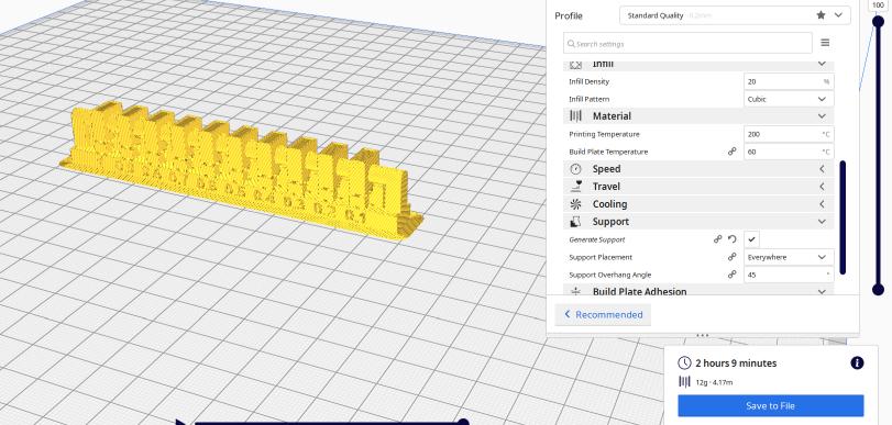
I also checked with the right cursor the layers of the printing.
And I finally download the .gcode file and put it on the micro SD card readable by the device. Then I started the printing and checked if everything started well.
The result is pretty good at the end, I just have to remove the support.
First I tried with cutter warm vibre but it melt my shape. So I used a normal cutter, I removed the support, but maybe because of the infill I set at only 60%, the shape broke in two parts when I made a lever with the cutter.
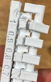
We still can se the result and now I know how to set the clearance I need to design my shapes.
Overhang
I also made the test of overhang to see how the printer is dealing with printing overhang without support. Here is .stl file for overhang. This files comes from the fabacademy website
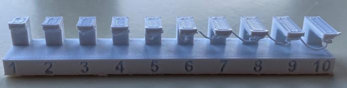
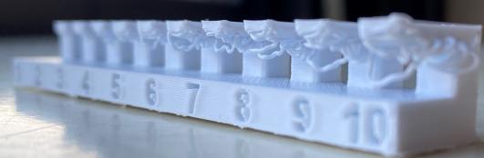
At the end, with a 10 mm overhang, the printer can still do it but it is becoming really messy under.
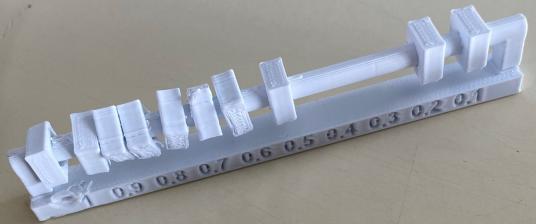
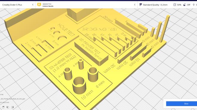
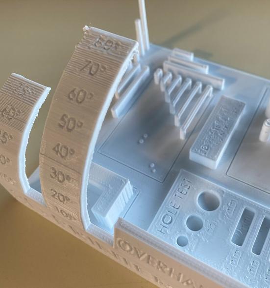
Full board test
I looked for a test board that print many test, to check until where I can set angled shapes without support, the bridges, the precision of the printer in doing cylinders, and holes in circles and rectangles. You can find the file on thingiverse.com
Here is the final result that should appear.
First the Creality ender 5 plus didn’t print the writing on the the shape. We can read the writings that are make with holes.
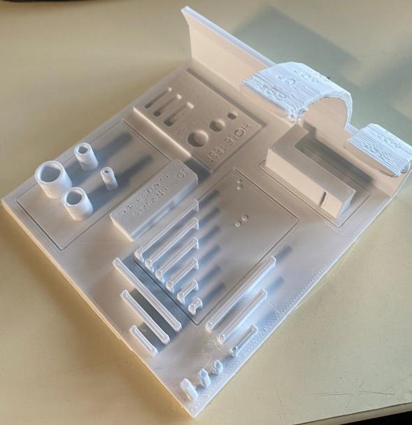
To test the precision of the priting I compared the size of what the result would be and what were really print.
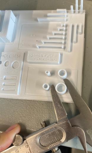
For the cylinders, there is a difference of 0.1 mm.
| Expected | Real |
|---|---|
| 10 mm | 9.9 mm |
| 8 mm | 7.9 mm |
| 6 mm | 5.9 mm |
| 4 mm | 3.9 mm |
For the hole test, circles the printers is not really precise
| Expected | Real |
|---|---|
| 8 mm | 7.6 mm |
| 6 mm | 5.2 mm |
For the hole test, rectangles the measures are really good
| Expected | Real |
|---|---|
| 4 mm | 4 mm |
| 3 mm | 3 mm |
| 2 mm | 2 mm |
All the measure depends also of the measurement accuracy.
For the angles, from 50 degrees, we start to see really the lines of platic printed. For the
Conclusion
As a conclusion we can make this small table which contains all the important information to compare the printers used :
| 3D Printers | Ultimaker 3 extended | Creality ender 5 Plus |
|---|---|---|
| Printing time | 5h 28min | 5h 49min |
As can be seen, for the same setting the two printers will not have the same results. You can see that the Ultimaker 3 Extended is slightly faster than its competitor the Creality ender 5 Plus.
For the same (or almost) level of precision you can see that each machine has different technical specifications.
Individual assignment
3D printing
Difference between FDM & SLA
There is currently competition between two 3D printing technologies: FDM (Fused Deposition Modeling) and SLA (Stereolithography). The two methods are very different, but each has the potential to make its mark on the 3D printing world. Each has its own advantages and applications.
FDM
If you watch a video of a 3D printer in operation, it is very likely that you will come across a programmed printing nozzle in a three-dimensional space, extruding molten plastic to draw a precise shape. This is a very popular image and as such FDM is the most popular printing technology.
First, you need to send the right information to the printer. An STL or OBJ file, for example, which contains the information about the layering of the object, for layer-by-layer filament deposition. This is one of the easiest ways to program the printing of an object. However, the more complex or small the object, the thinner the layers need to be, and not all printers are equipped to print very complex objects.
Once the slice file is sent to the printer, the printer still needs material. The printer uses filaments made from raw materials that can be heated and pushed through the extruder. Typically the material is made of plastic, but there are many different variations, which can be combinations with other materials to take advantage of other properties.
So, following the slice file, the printer heats the material and extrudes it through the nozzle while it draws the shape, one layer at a time. Once finished, there is a very slight delay for the layers to bond together. The object is finally finished, and ready to use!
The advantages :
- For hobbyists, printing at home: FDM printers are becoming very affordable and quite easy to use. In addition, their materials are widely available.
- FDM is recommended for beginners to learn 3D printing, it is becoming more and more precise, it allows to print finer and more complex objects.
- It is the most widespread desktop 3D printing technology with a large community.
- It is still very easy to operate and use
- 3D printers are affordable, with prices starting from 200€.
Disadvantages :
- FDM printers have difficulty with very fine details, or objects that require moving parts.
- They can’t really create high-end prototypes, although they can be very meticulous.
- Coding and calibration must be very accurate for the printer to work properly. So on some printers you really have to “show” the printer how to start printing an object.
SLA
Technically, the Laser or LCD/DLP method was created a few years ago : It uses a very sensitive plastic resin. In its normal state, the resin has a more or less liquid form. However, when exposed to the right kind of light, the resin hardens permanently.
SLA printers simply apply this process. They also do this layer by layer, but instead of extruding material, they cure resin in a tank.
The process starts with liquid resin in a tank, and a screen that can directly expose the lowest resin layer in the tank. The SLA printer uses a very complex 3D file to know where to direct the light to cure the resin properly. Typically, the printer includes a base to build the object on. The base moves through the liquid tank, while the object is formed, layer by layer.
The advantages :
- The models created offer better accuracy and resolution
- Due to the quality of the models, the technology can be used in many sectors
- Technical resins specially developed for dental or jewellery applications
- Some varieties of resins offer designers the possibility to create very hard objects. They are harder than FDM objects and therefore have practical properties.
- SLA is more suitable for prototyping and even for some mass production.
Disadvantages :
- SLA 3D printers are often more expensive than FDM
- It is not possible to combine different resins or colours
- Technical knowledge is often required to operate the machines properly
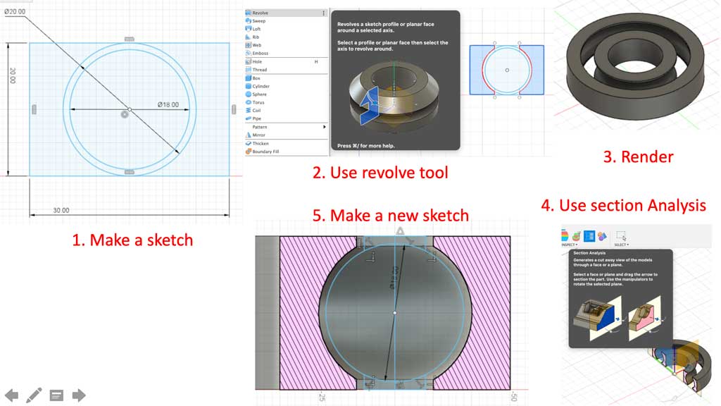
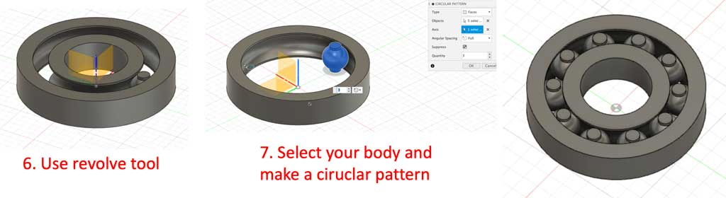
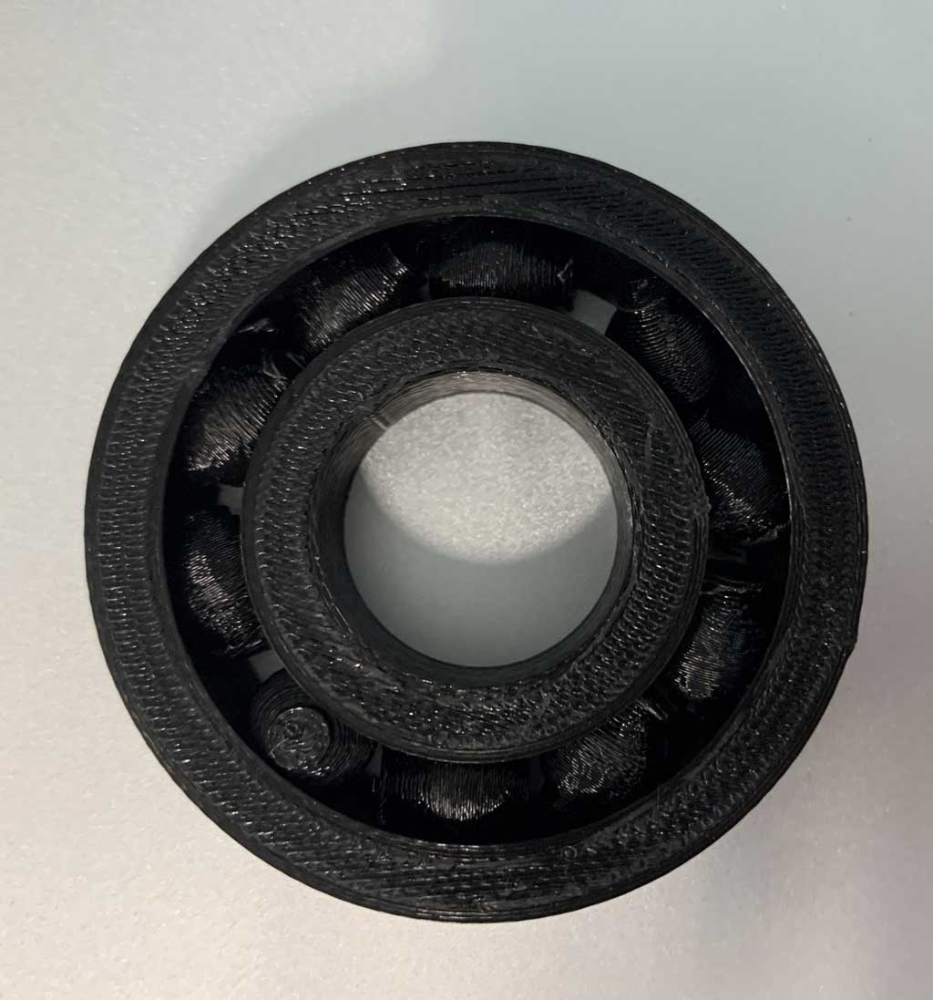
For my individual exercise I decided to make a small bearing. A bearing cannot be created in a subtractive way, so this object makes the work we have to do this week.
At first I drew it on Fusion360. In a group test I saw that a minimum clearance of 0.2 mm was needed between two pieces to allow them to move. So I used this test to make my bearing and I decided to put 1 mm of clearance on each side of the ball.
Once saved in STL format I imported it into Cura.
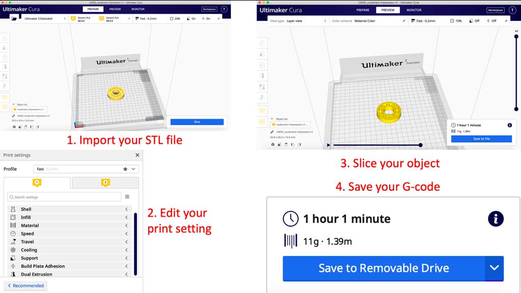
Here are the settings I have chosen for my bearing:
- Material : PLA
- Layer height: 0.2 mm
- Wall Thickness: 0.8 mm
- Nozzle: AA 0.4 mm
- Infill: 10% tri-hexagon
- Printing temp: 205°C
- Bed temp: 60°C
- Print Speed: 70 mm/s
- No support
- No plate adhesion
Printing time 1h 1min
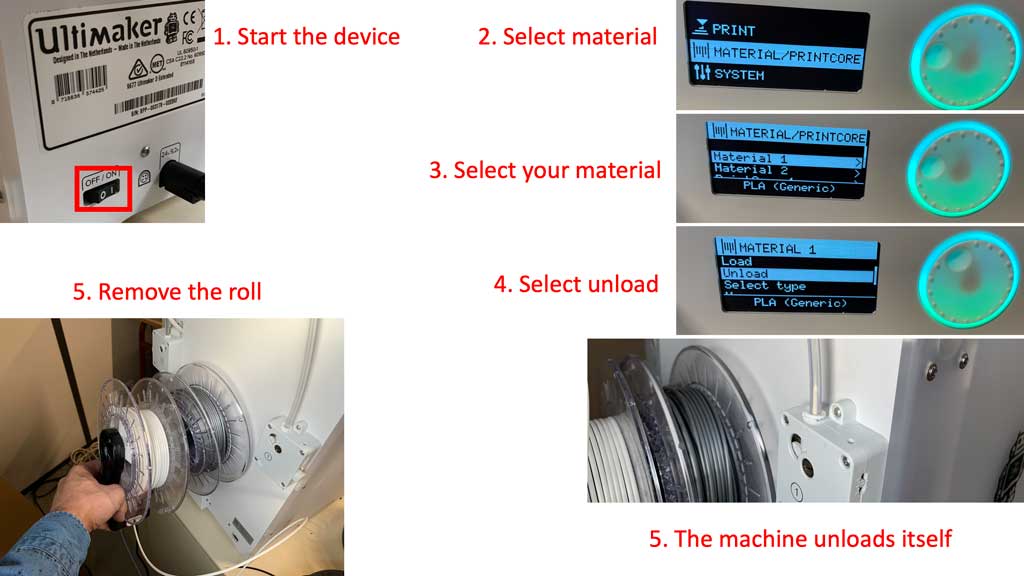
How do I change the filament on an Ultimaker 3 extended?
- Switch on the machine using the switch located at the back of the printer.
- Move around using the wheel in the hardware menu.
- Select the unload option
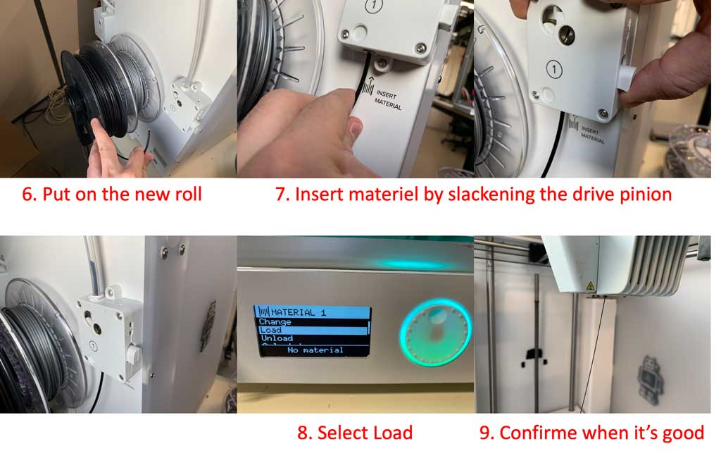
- At the back of the machine is the drive pinion, release it with the button on the side and pull the few filament yarns remaining.
- Remove the old bobbin and insert the new one (pay attention to the direction of the thread).
- Come and insert the new filament into the drive system.
- Return to the menu and select load
- Confirm when the filament comes out.
When you have changed the filament and imported your file into the printer using a USB key, you can go to the “Print” tab and select your file.
Hero shot
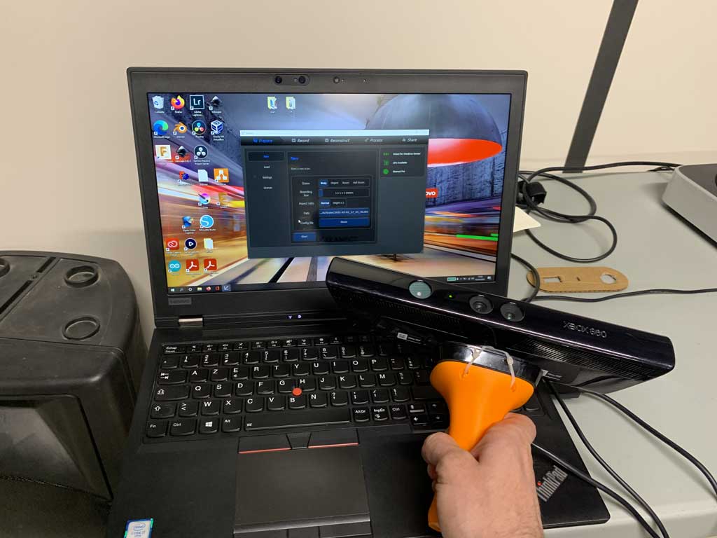
3D scanning
To discover 3D scanning I wanted to scan Antonio. For this I used a kinect and the Skanect software.
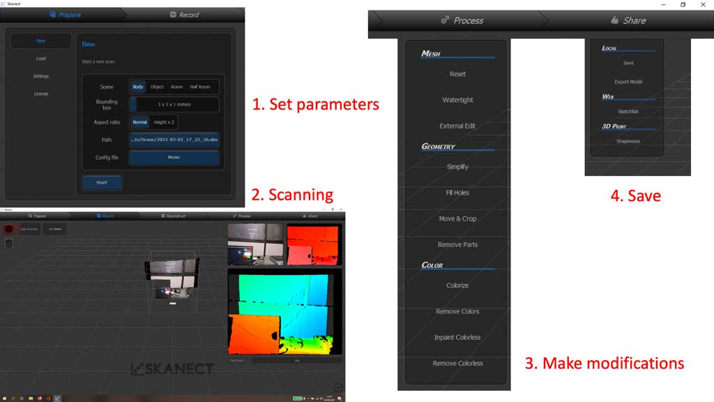
How to use Skanect ?
- Connect your kinect to your computer
- Open the Skanect application
- Choose the dimensions of your object to be scanned then click on continue.
- As soon as you are ready to scan you can press start and start scanning.
- Once finished, click on finish and go to the rendering tab.
- In this tab you can make small changes (fill in a hole, smooth out appearances…).
- Export your file in the format you want.
Here is the result:
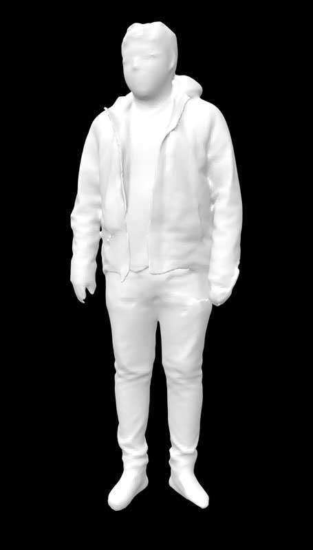
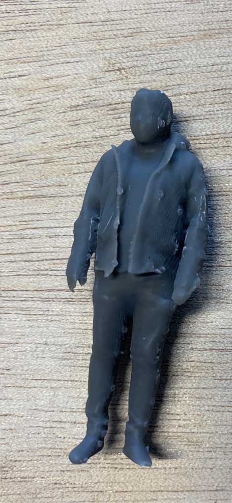
To continue having fun I decided to print it with the FormLabs printer. This printer uses resin to create the desired model.
To do this we imported it into the PreForm software and then used the magic tool. With this tool the software automatically creates the best settings for printing.
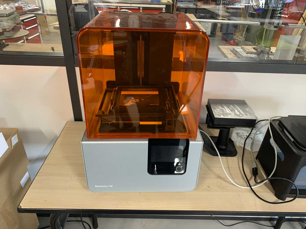
We use a Forms2 and as a grey resin V4.
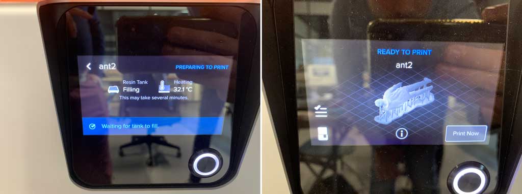
After 45 minutes of printing we have this result.
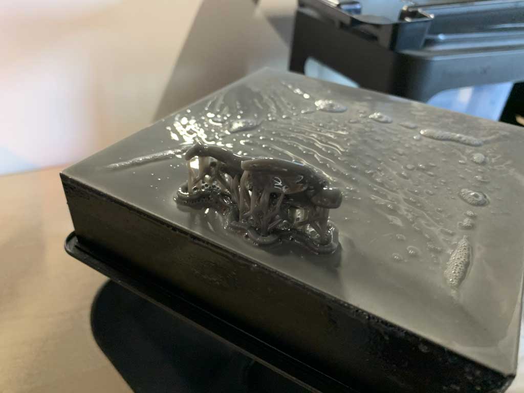
We must then detach our object to clean it (resin particles remain) in isopropyl alcohol.
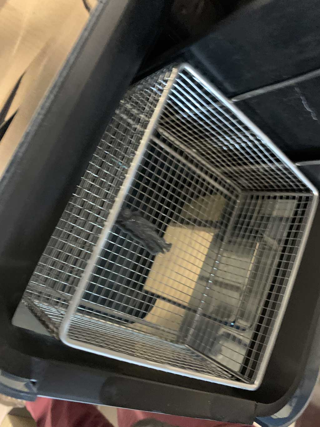
After 20 minutes in a stirring bath of isopropyl alcohol our object must be dried. To do this we place it in a machine that will heat and give off a powerful light. After 30 minutes of drying in 60°C we can take our piece and remove all the small support.
I find this values in a website of Formlabs. Simply select your resin from their website and it gives you all the time you need for cleaning and curing.
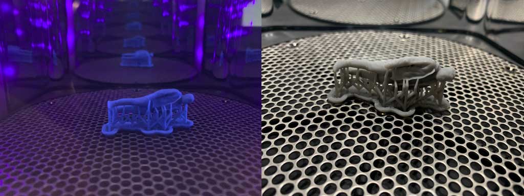
The brackets have a shape at the end that allows for quick unhooking. The supports are 1mm in diameter over their entire length but at the point of contact the supports measure only 0.7mm. This makes disassembly easy and leaves very little trace on the object.
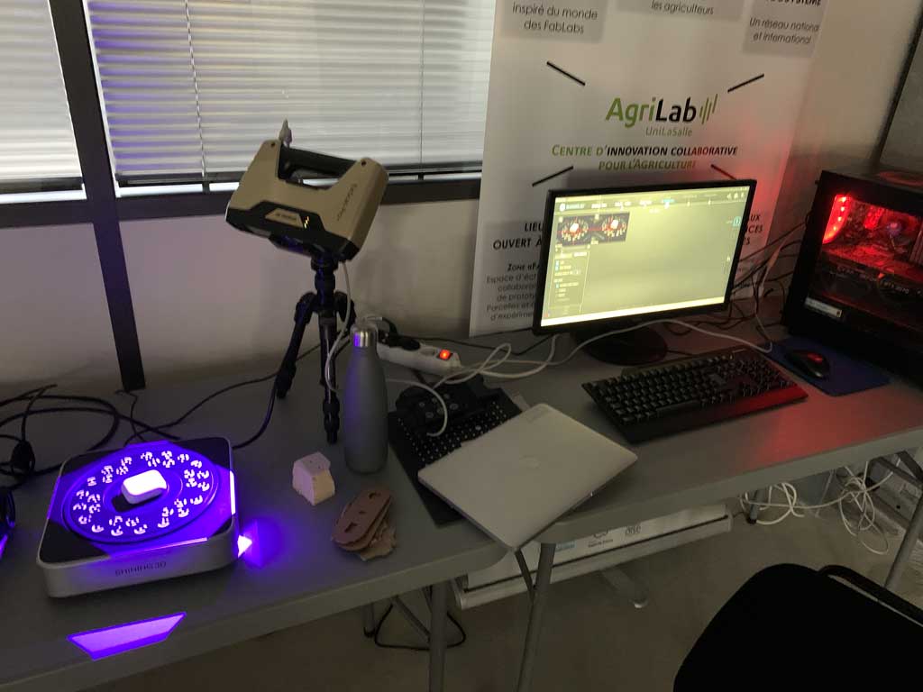
EinScan Pro +
To try another type of scan I decided to scan my airpods. For this I used the AgriLab scan which is an EinScan Pro + with a turntable. This scanner works with the Einscan pro software.
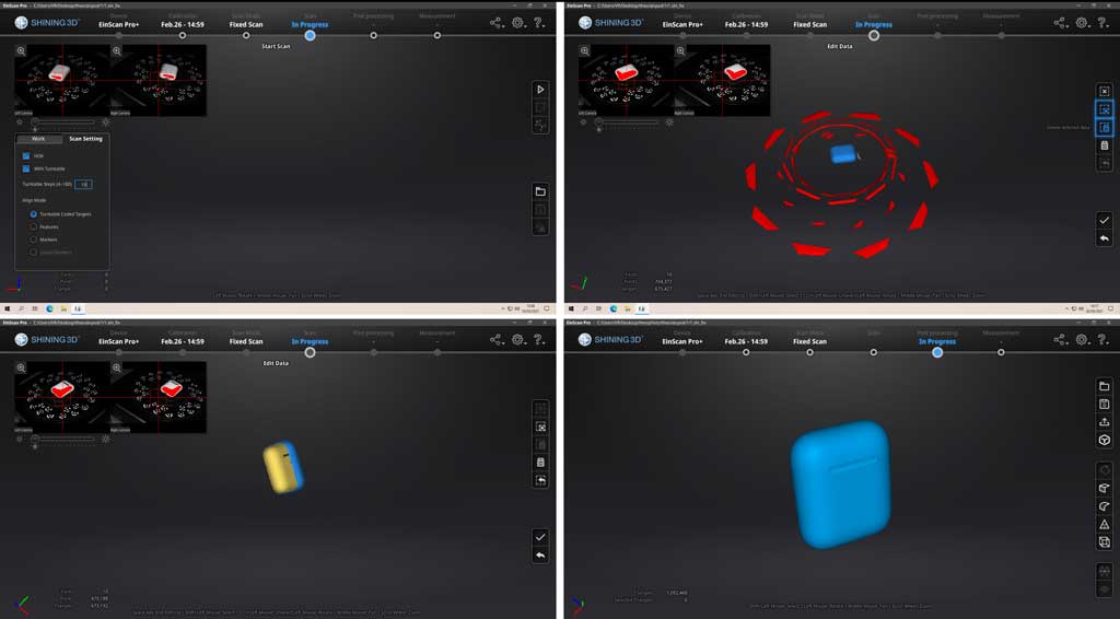
In order to scan an object you need to :
- Open the EinScan Pro software
- Selected your scanner and scanning mode.
- Creates a project
- View live if your object is in the frame
- Choose the turntable and the number of stops it should make to scan. If you select a low rotation angle then the turntable will stop often and make several images.
- Start the scan
- Result of the first impression
- Clean the contour of your object by pressing shift+left click and select the reverse option to select the parasite data.
- Delete parasite data select
- Click on “ok” and start another scan from another side (do this as many times as necessary to scan your object completely).
- View it and export it in the format you want.
Here is the result of the scan:
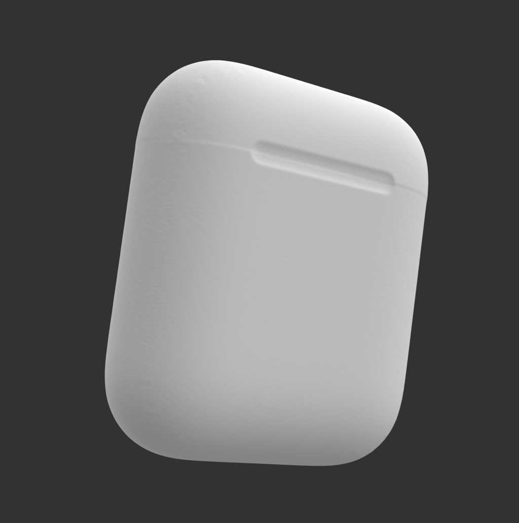
The scanner can also be used without the turn table, in which case it is up to us to rotate the object. We can also scan larger things, just take the scanner in your hand and move around your object to be modelled.
However, if you scan without the turntable you must manually register the size of your object. On the turntable there are markers for the scanner which allow you to give the object a scale of size. Without these markers the scanner does not know the exact size of your object.
If you want to use the scanner without the turntable, you will have to place marks on your object so that the software can combine the different images together.
Only for objects with low details, by example my airpod box because it’s very smooth
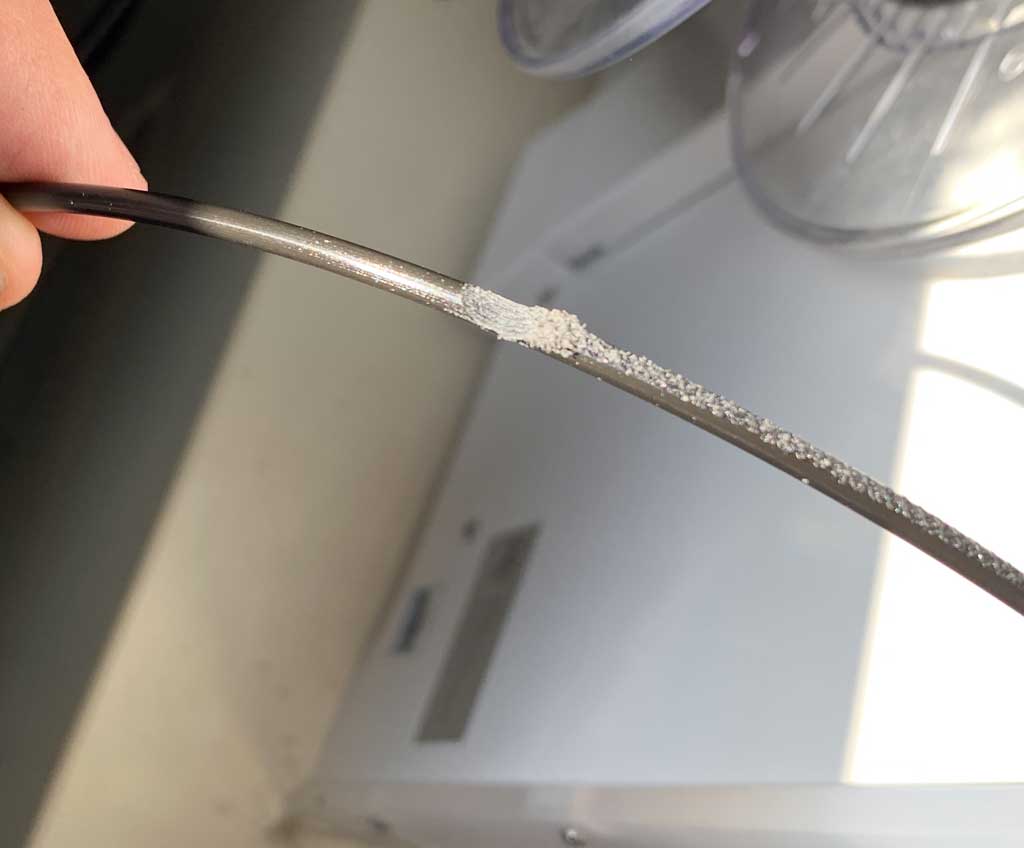
My mistake
When printing my bearing I had the unfortunate surprise of not understanding why the printer continued to print but nothing was coming out of the nozzle… I think it was a lack of filament but the reel was still new… The drive pinion turned well but the filament did not move. I then unloaded the filament from the machine and found that the filament was stuck in the system.
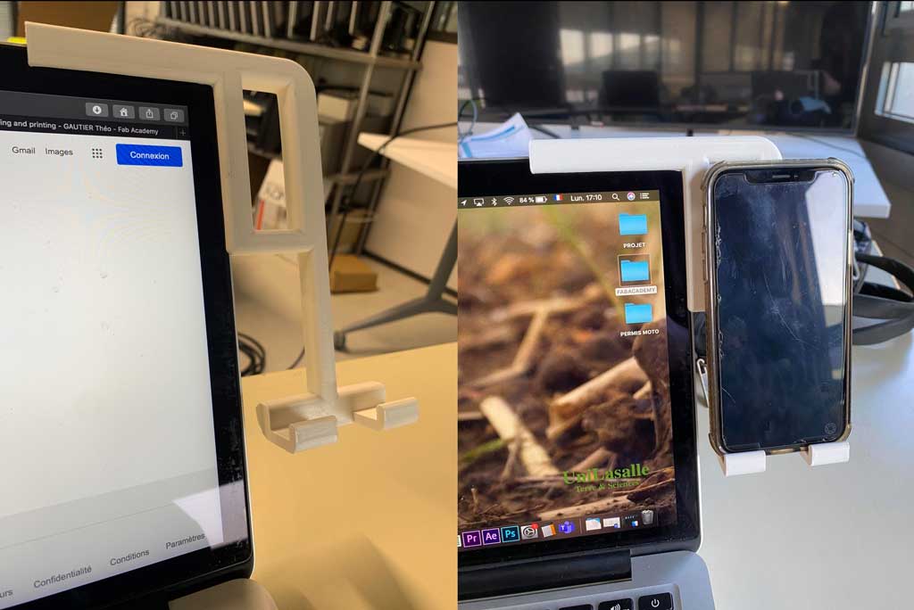
Bonus
During this week I also decided to make a mobile phone holder to be placed on the side of a Mac screen. I have a bad habit of putting my phone on the side of my screen but it blocks visibility a bit. So I decided to create a small holder that is positioned on the screen stop and allows you to put your phone on it. This was supposed to be my project of the week but my instructors told me that this object was not valid to validate the work. So that’s why I did a small bearing
Conclusion
It was a very intense but also very interesting week. Being able to handle professional machines like the scanner is a real opportunity for us and I am very happy about it. Today 3D printing is becoming more and more popular and it is now very easy to have a 3D printer at home for a few hundred euros. That’s why having the chance to learn the basics of volume printing is very interesting and allows us to move forward into the future.
Files
STL Files
F3D files