17. Wildcard week
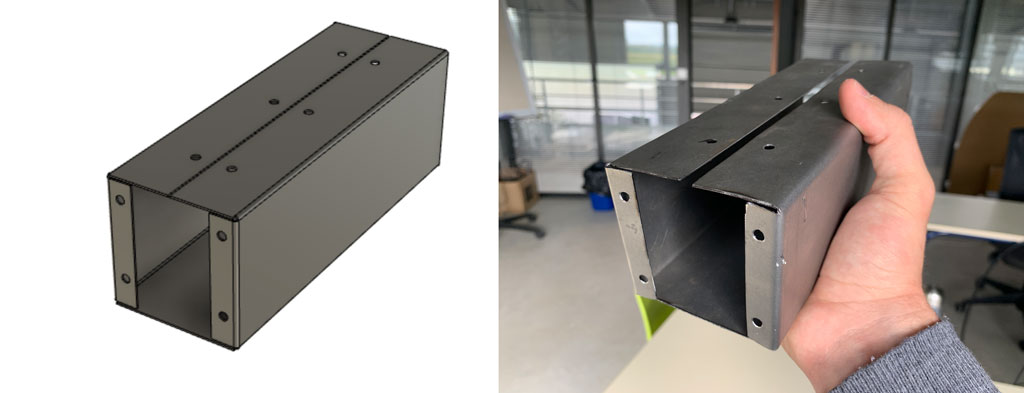
For the wildard week I decided to work with metal. Iron is a material I like to work with. I took the opportunity to work on my final project. The wheel motors are located under the robot’s chassis, so they are susceptible to shocks, splashes and so on. So I took advantage of this week to make some motor casings to protect them a little bit. To do so, I made the plan with Fusion360, exported the schematics and then cut a piece of metal with a grinder before bending it.
Assignement
Design and produce something with a digital fabrication process (incorporating computer-aided design and manufacturing) not covered in another assignment, documenting the requirements that your assignment meets, and including everything necessary to reproduce it.
Hero shot
Description of the machine
At AgriLab we have a manual bending machine of the brand Metallkraft. This bending machine is equipped with a segmented apron which allows for more complex bending. The ease and precision of operation thanks to the quick adjustment of the table makes this bending machine very useful.
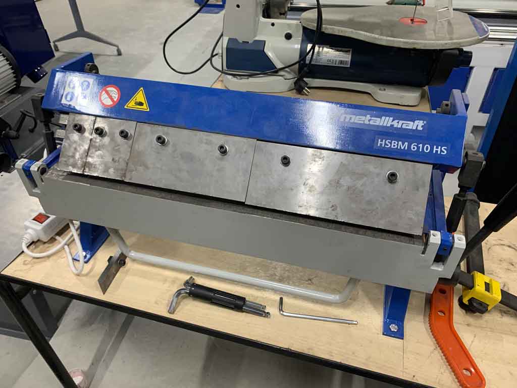
| Model | HSBM 610 HS |
|---|---|
| Max. working width | 610 mm |
| Max. thickness | 1.0 mm |
| Max. bending angle | 135° |
| Dimensions (L x W x H) | 850 x 360 x 420 mm |
| Net weight (gross) | 42 kg (48 kg) |
Making the box on Fusion360
To make the pattern for my bending I used Fusion360 and the “Sheet metal” tool. These tools can be found in the “Design” tab.
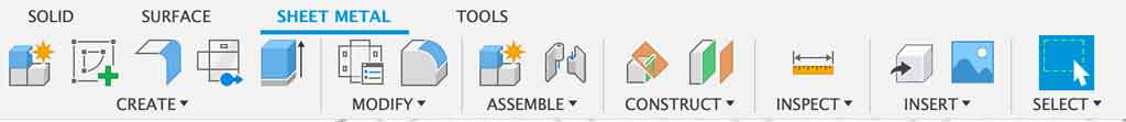
As you can see the structure of the headband is not the same as in the “Solid” tab. There are a few more options that allow you to make bends. The options we are most interested in for the engine cases are “Create a new sketch”, “Flange” and “Unfold”. These three functions in fusion360 will allow us to make the engine cover the way we want it.
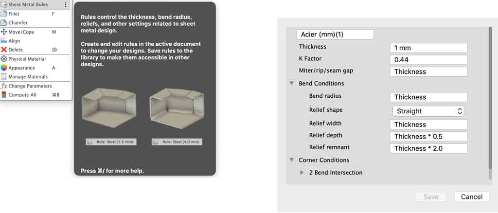
Before starting anything you need to know what material you are going to bend next. For my part I want to bend a 1mm thick steel sheet. It is also preferable to know the machine, and its technical characteristics on which you will bend. Each machine has advantages and disadvantages, so it is important to visualise the constraints before designing your object.
Once you have all this data, you need to fill in the table called “Sheet Metal rules”. Each material has a different bending behaviour and a different thickness, so the design will not be the same between 0.1mm thick paper and 3mm thick sheet metal for example. The most important element to know is also the K factor.
The K factor
The k-factor is a value that allows the position of the neutral fibre on a bent part to be determined. The k-factor is always positioned in relation to the inside of the fold. To know the position of the neutral fibre, the k-factor must be multiplied by the thickness of the sheet.
Example: The k-factor is 0.3, the thickness of the sheet is 5mm. The position of the neutral fibre is therefore 0.3 x 5 = 1.5mm from the inside of the fold.
The k-factor depends on several parameters:
- The bending tools: Vee and knife
- The thickness of the sheet
- The material
- The bending angle
- The rolling direction can also have an impact
The calculation
In order to determine the k-factor, a series of tests must be carried out on the bending machine using test specimens of a given size. The important dimension is the length of the specimen, as the width has no impact on the k-factor. L is taken as the length of the specimen.
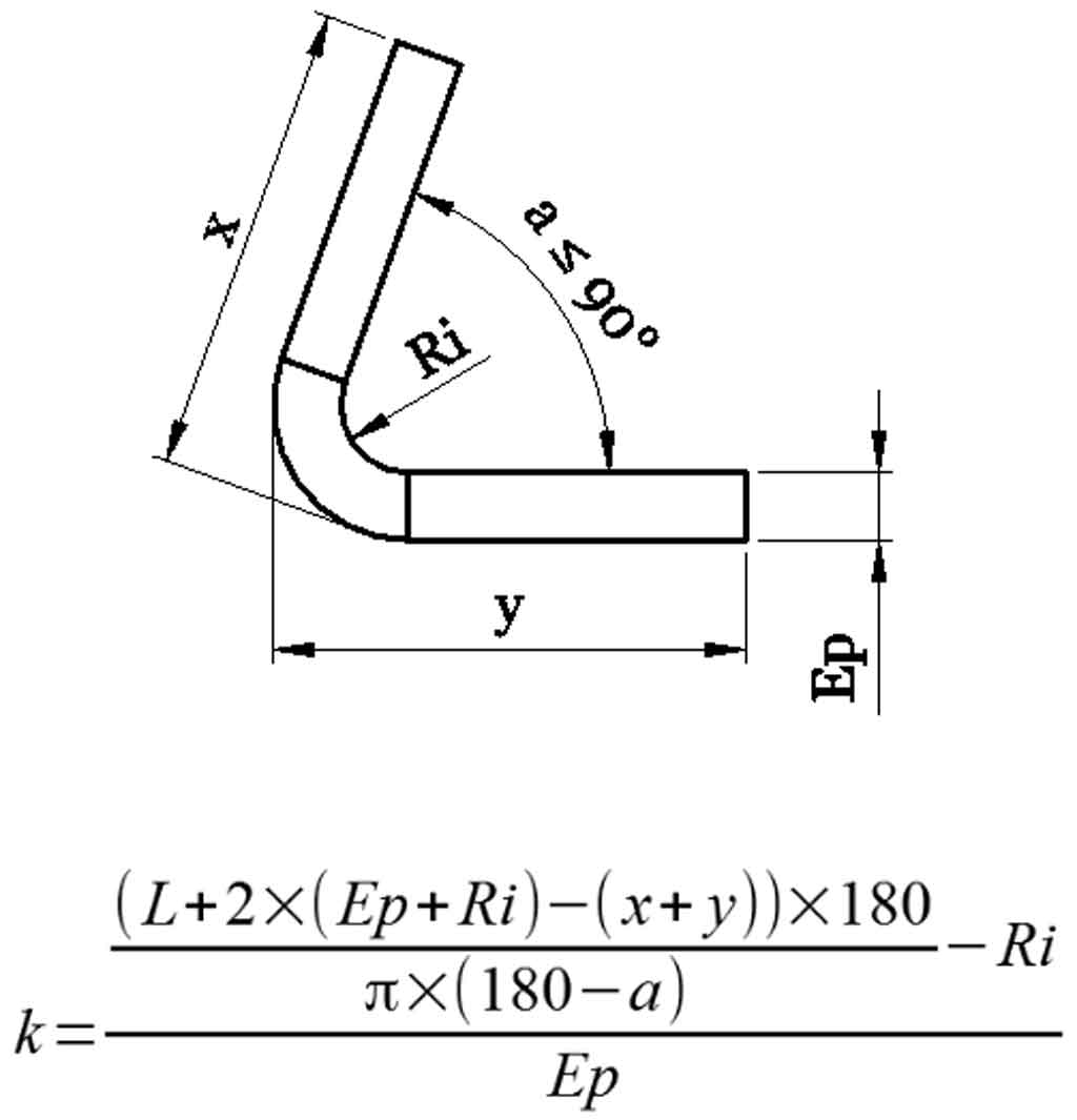
After several searches on the internet I found a K-factor value for a 1mm thick sheet metal and this type of tool equal to 0.44.
The drawing
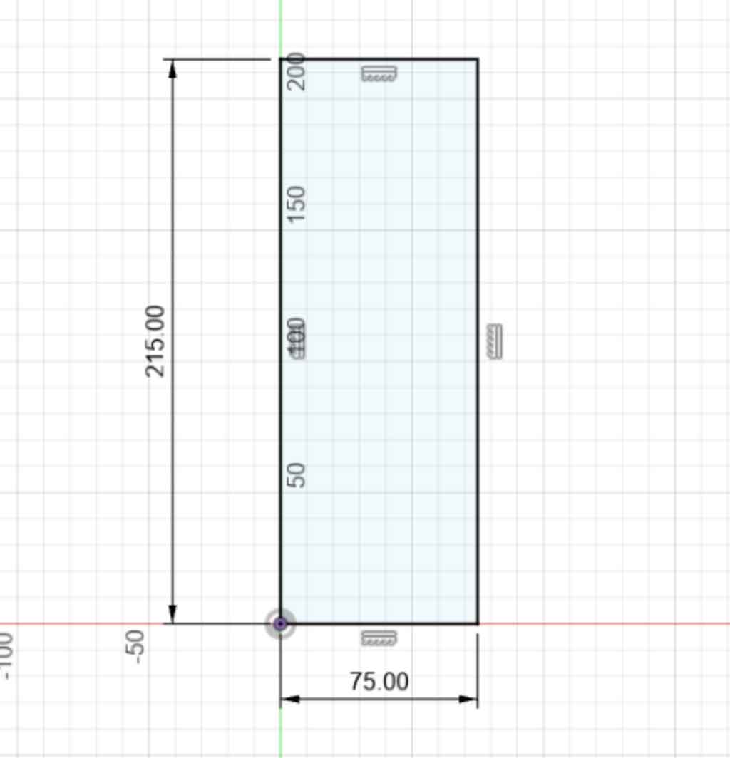
Start by making a sketch of the desired length and width. For my part after having looked at the datasheet of my future motor the dimension of my box must be 215mm x 75mm.
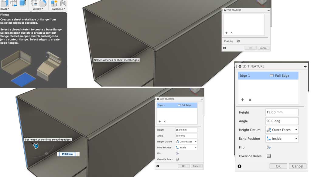
Once you have made your sketch you need to use the “Flange” tool.
The Flange tool is very simple to use. Select a edge you want to flange and then adjust the length you want. You can also change the bend angle, bend orientation and bend position.
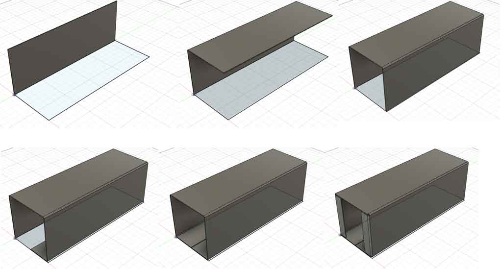
I then used this tool several times to build my box. Here are the different stages of construction:
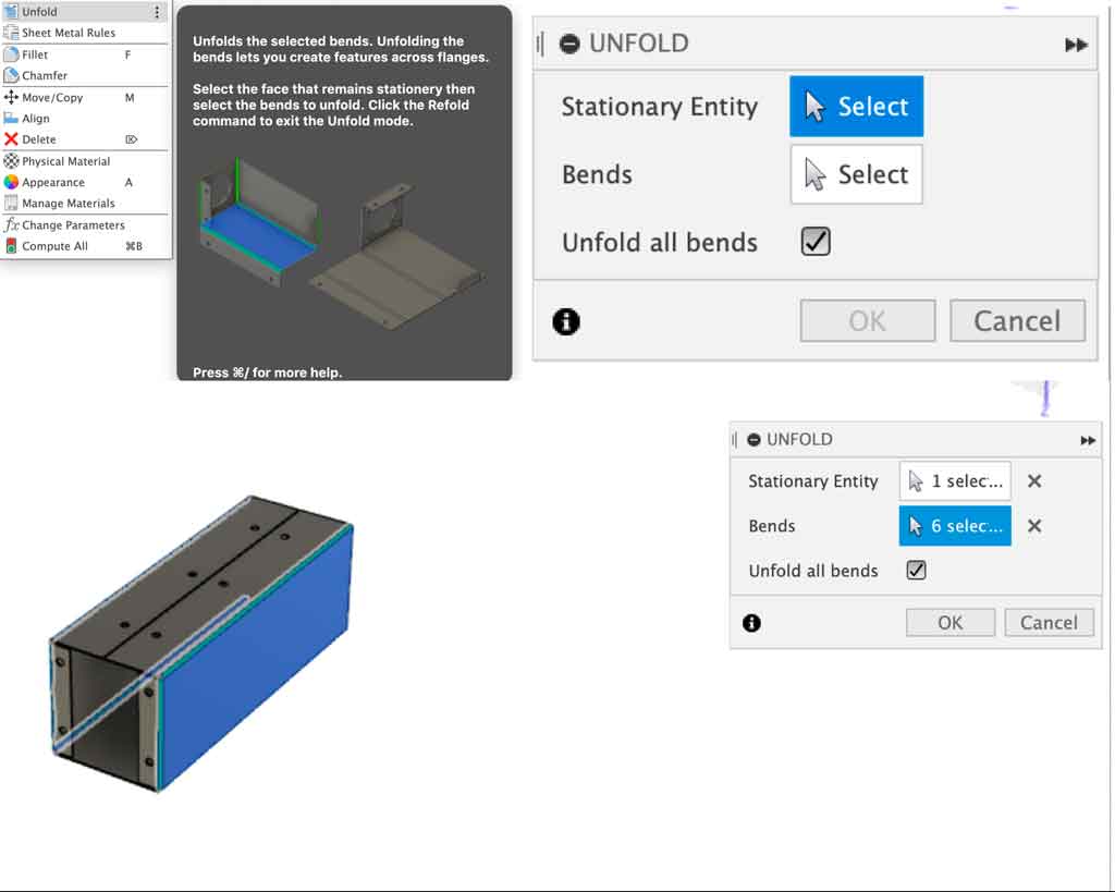
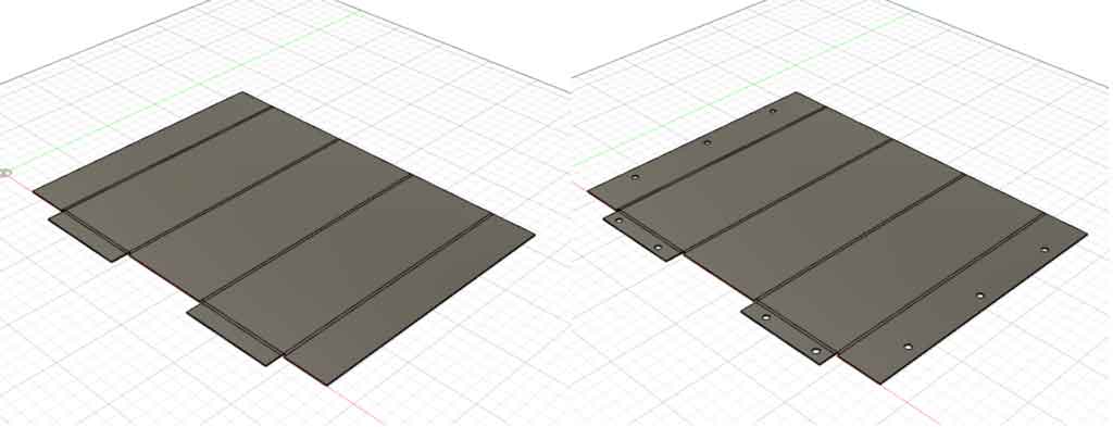
To make my fixing holes I unfolded the box with the “Unfold” tool. This tool is also very easy to use. Select a side that will be fixed and select the bends you want to unfold. I wanted to unfold the whole box, so I checked the box “Unfold all bends”. Once unfolded I made my different fixing holes.
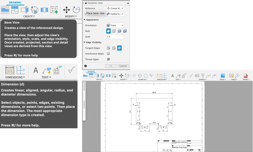
Exporting the construction plan
In order to have all my measurements on a paper to go to the workshop I made a construction plan with the measurements. I then exported it in PDF format so I could print it.
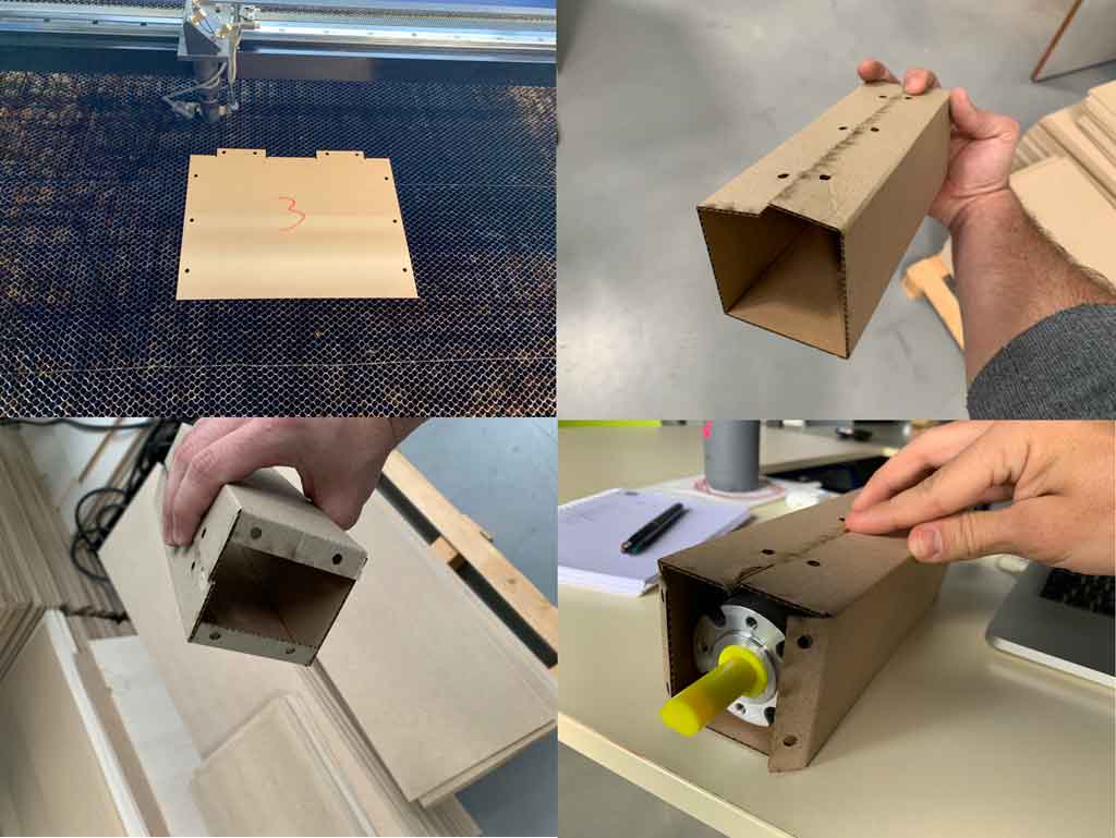
Realization a test with the laser.
Before starting the final cutting of my boxes I decided to make a test with cardboard. This test allowed me to see if there were any mistakes. So I cut some cardboard with a laser to check the dimensions of my box quickly. After checking, my engine fits well in my box, so I can start cutting my metal parts.
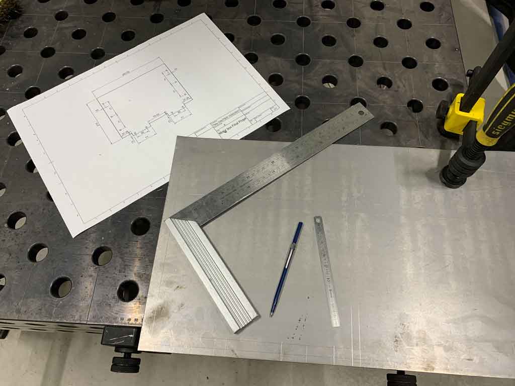
Tracing
Before cutting out my part I had to trace on my sheet metal the template of my box. For this I used a measuring tape, a scribe, a bracket and my plan.
Cutting
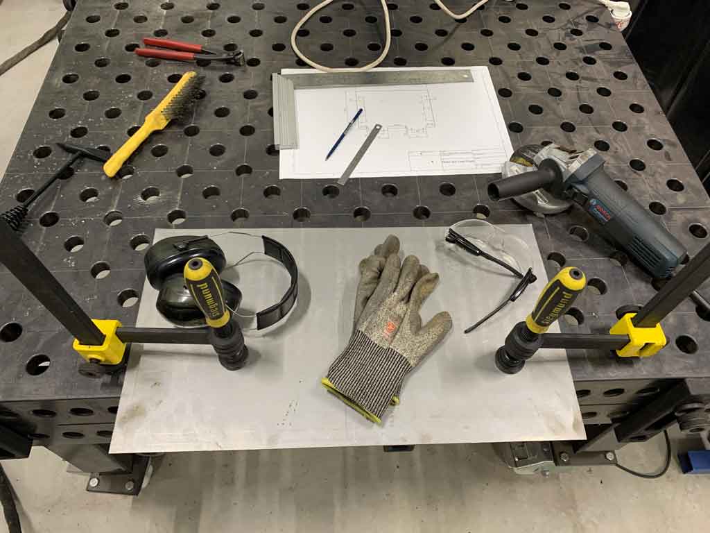
When I was done with the tracing I started to cut the box. For this I used a grinder. This tool being potentially dangerous, there are personal safety equipments that are essential. Hearing protection because this operation generates a lot of noise. Safety glasses because this technique sends particles of molten metal in all directions, it would be very painful and serious if one of these particles arrives in my eyes. Gloves to protect your hands from possible cuts or other.
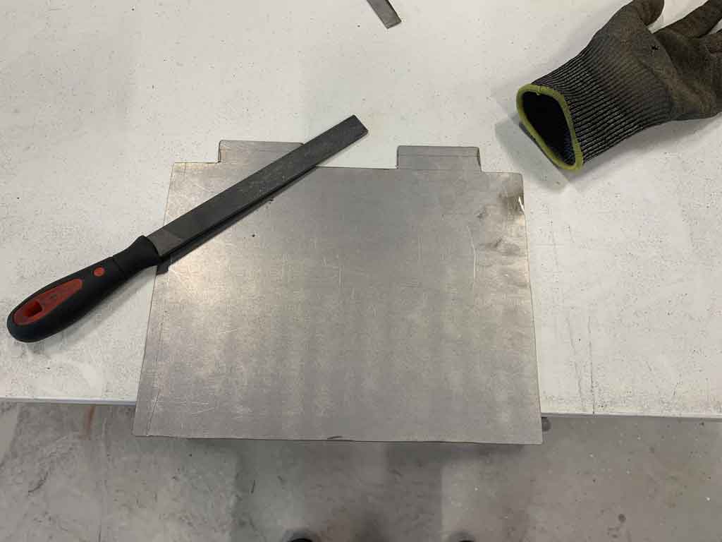
Deburring
When a steel sheet is cut with a grinder, burrs are generated. These pieces are very sharp, so it is preferable to sand them in order to round off the edges and thus limit the risk of cutting.
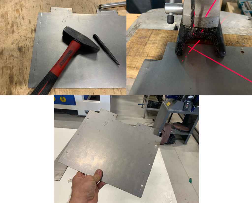
Drilling
Before bending, it is better to drill the holes for the fixing. To do this I marked my hole locations with a punch and a hammer. This will guide the drill bit when drilling. I then used a drill column with a 5mm diameter drill bit.
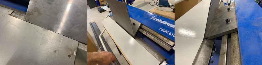
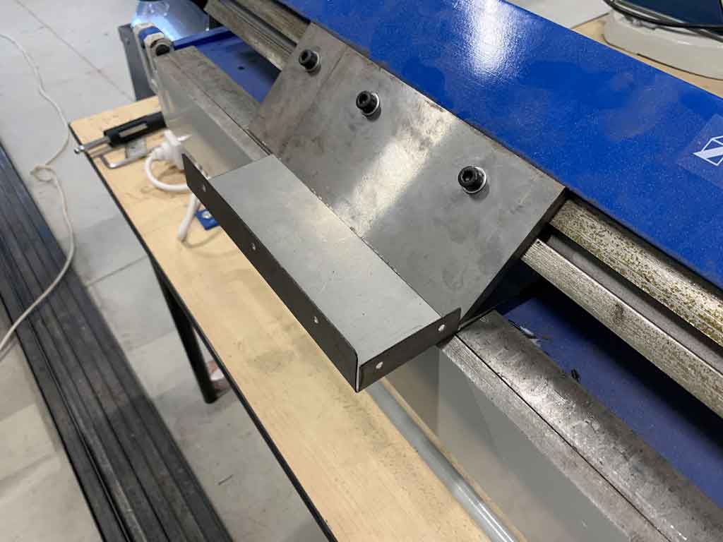
Bending
The last step to make my protective covers is the bending. For this I used the bending machine described above. I traced all my bending lines beforehand. Then I just press the sheet by aligning the line on the bending tools. When everything is well blocked and positioned, you just have to lift the removable part and stop at the desired angle. The machine does not have an angle measuring tool so you had to use a square or an angle ratio to check your angle. For my part I only had 90° angles so I only used a bracket to check my angle. When the angle was not good I put my piece back in the bending machine to make it perfect.Repeat the operation as many times as necessary to close your box.
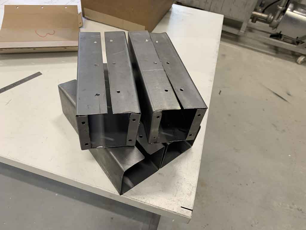
Hero shot
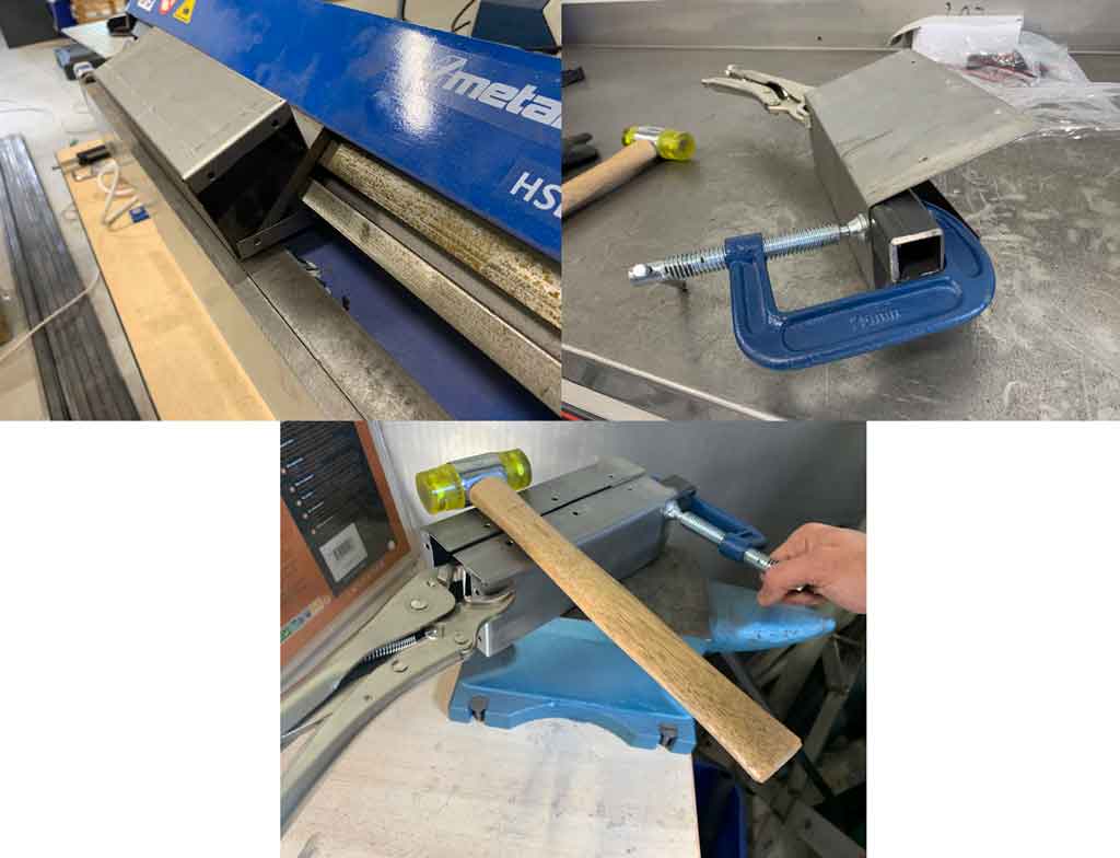
Mistake
The bending machines do not allow to close a box completely, so I had to find an intermediate solution to fold the last side. When I wanted to fold the side the other sides of the box would touch the structure of the bending machine. So I decided to use a metal tube, a hammer, a clamp and a vice grip to close my box. I placed the tube where I wanted to bend my side and then fixed it firmly with a vice grip and a clamp. I then stood on the anvil and hit the hammer to bend the last side.
Conclusion
This week was a very satisfying week for me. Since the time I wanted to work with metal, I was finally able to make a metal piece. Moreover, it allowed me to progress on my final project. After thinking about it, I should have made the casings in a different way to make it easier to assemble and disassemble them. However, I will still use them for my robot.