Computer-controlled machining
COMPUTER-CONTROLLED MACHINING
This is the content we had covered this week:
W7 - Computer-controlled machining
- CNC
- Tools
- CAM
Assignment
-
Group assignment: Do your lab’s safety training. Test runout, alignment, speeds, feeds, materials, and toolpaths for your machine
-
Individual assignment: Make (design+mill+assemble) something big (~meter-scale)
This week we’ve been assigned to create something BIG for once. So it comes with the challenge of understanding, using CNC machining and make it work!.
HOW CNC WORKS
COMPUTER-CONTROLLED MACHINE
Although we’ve already used a CNC when milling PCBs, in this case, I wanted to get deeper into understanding all the properties and parts of such a large piece of machinery.
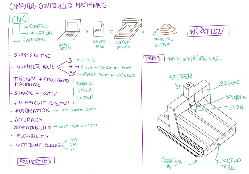
"Diagram showing CNC workflow, properties and parts. "
ENDMILLS 101
One of the critical aspects of CNC is endmills. There are many kinds with multiple structural properties that change the way you need to set up the machine and how the material removal works around the material.
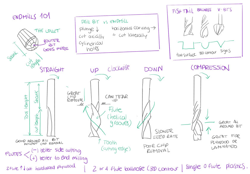
"Diagram showing different types of endmill and its properties. "
CNC SETUP
At first, setting up the CNC machine seems quite overwhelming. There are so many things to take into consideration, and even when you have them under control, each material, even each wood stock, might perform differently.
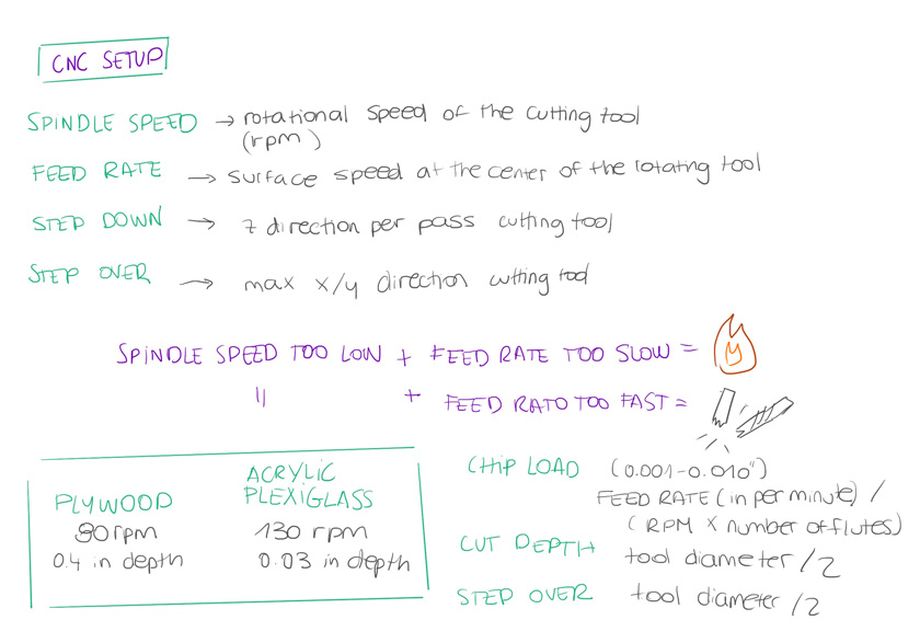
"Diagram showing CNC setup most important settings with some considerations. "
HOW TO MAKE SOMETHING BIG
Before tackling the individual assignment, the group assignment felt more critical than ever. Working as a team to decypher the complex pipeline and settings of the CNC was very helpful.
GROUP ASSIGNMENT
SAFETY TRAINING
After a couple of theoretical sessions, we were finally taught how to use the CNC. There were many security considerations, and making sure to follow them every time is compulsory to make sure anything potentially dangerous happens.
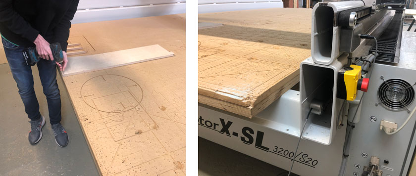
"LEFT: Screwing the material to the sacrificial board to make sure it doesn't move under operation. RIGHT: Emergency STOP button. Be always nearby in case the job has some issues."
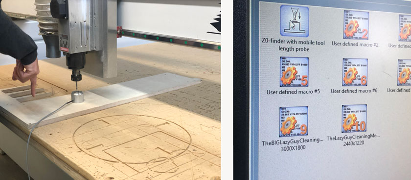
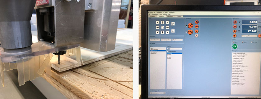
"LEFT: Zeroing the Z axis with the mobile tool length probe. RIGHT: Press to find Z."
CNC TESTS
We had a conversation around what we should test. There are many settings but we wanted to define some tests that could be handy for our projects.
We asked for advise to know where to start.
CHIP LOAD CHART
After choosing the material we were going to use, we looked up for the Chip Load Chart to know the range of safe values that we would test.
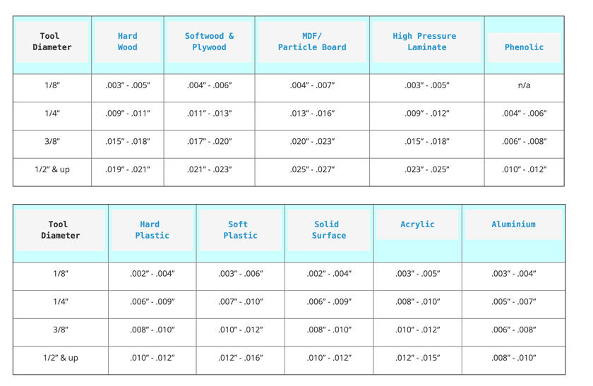
"Table showing chip loads ranges for multiple materials. We took the softwood & Plywood values for 1/4" "
CALCULATING SPEED & CUT
Here the calculations start.
-
1/4” = 0.635 cm –> we had a 6mm endill so this is the row we took .007” ( 0.1778 mm) - .010” ( 0.254 mm).
-
Feed Rate = RPM x number of flutes x chip load.

"Some of the calculations taking into account RPMs and the largest chip load. "
- RPM = feed rate / (number of flutes x chipload).
- Metric conversion: Divide inches per minute by 39.374.
I’m still a bit confused by some of the calculations, but I got a good understanding of the ranges we should use.
Shop Bot Bit, Feeds & Speeds document
TESTING DIFFERENT SPEEDS
We decided to test a wide range of speeds to later on produce a test with many pieces.
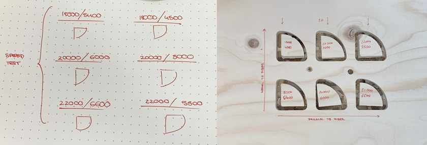
"LEFT: Drawing with different speeds. RIGHT: Pieces cut with different speeds. "
SETTING UP SPEEDS TEST
Our first test was very simple, it helped us to define what we thought were going to be the optimal parameters.
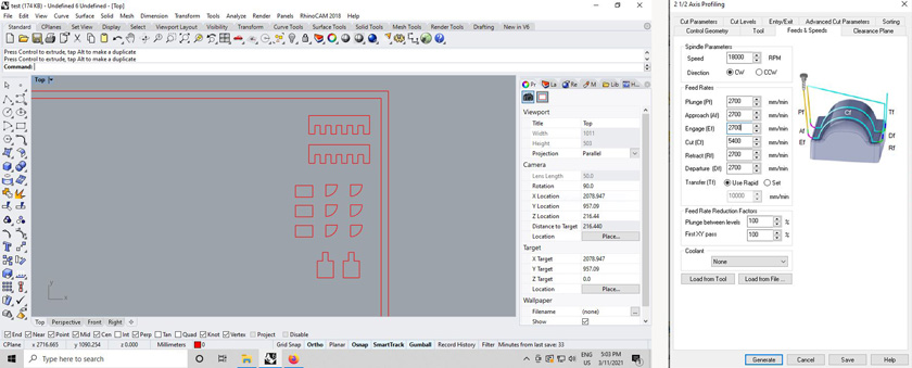
"LEFT: Using Rhino to design first test pieces. RIGHT: Setting up RhinoCAM. "
SETTING UP ENDMILL
The steps followed to setup the endmill were the same than the ones we learnt during pur safety training.
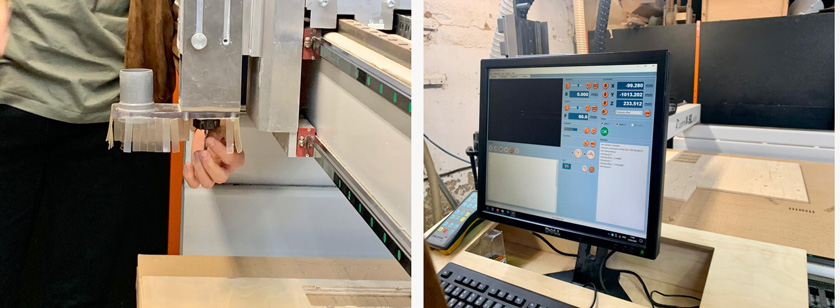
"LEFT: Placing Endmill inside the collet. RIGHT: Adjusting X-Y axis."
SETTING UP HOME
Final touches before launching the test file to cut.
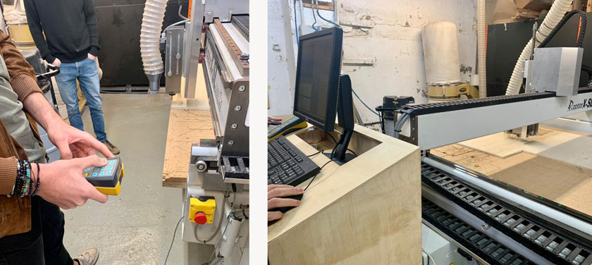
" LEFT: Ajusting X-Y using remote control. RIGHT: Launching file."
REMOVING TESTS
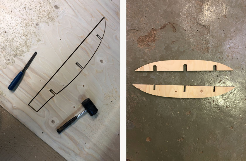
The first test was successful. As we added some tabs in the profiling layer to prevent pieces from flying away, we used a chisel and a mallet to remove the parts.
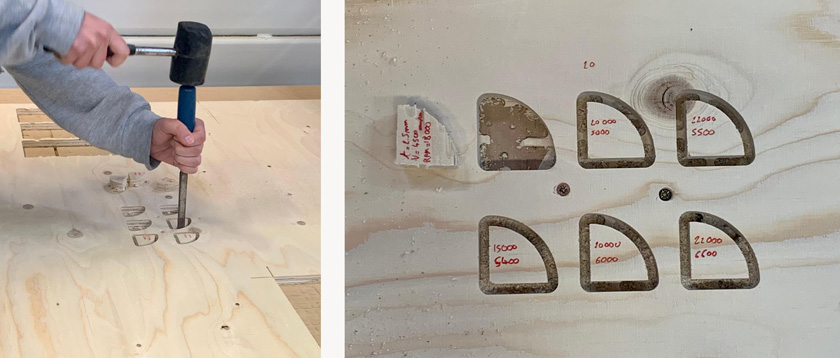
"LEFT: Nil removing wood test with a chisel. RIGHT: Labeled pieces with the different speeds. "
SETTING UP ALL TESTS FOR FITTING
We set up different profiles: engraving the screws, profiling, pocketing. There are many values that need ajustment:
- Spindle Speed (RPM)
- Cut
- Plunge (Cut/2)
- Approach (Cut/2)
- Engage (Cut/2)
- Retract (Cut/2)
- Departure (Cut/2)
- Cut parameters –> Tolerance
- Cut parameters –> Cut Direction
- Cut parameters –> Stepover
- Cut levels –> Total Cut Depth
- Cut levels –> Rough depth
- Cut levels –> Total Cut Depth
- Cut levels –> Rough Depth Cut
- And some more…
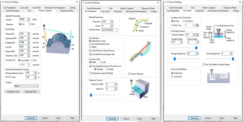
"LEFT: Feeds & Speeds Tab RhinoCam. MIDDLE: Cut Parameters RhinoCam. RIGHT: Cut levels RhinoCam."
TESTS DESIGN & CNC RESULT
The final test included:
- Thickness of cut for fit.
- Radius for fitting a wooden rod.
- Tab ladder fit with different lengths.
- Flexible surface with plywood.
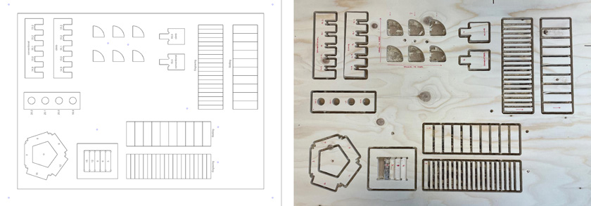
"LEFT: Rhino file with test. RIGHT: Test right after CNCing."
WHAT WENT WELL
Variety of tests: We were able to test many features that interested us.
Repeatable settings: Some settings can be reused to cut my individual assignment
WHAT COULD BE BETTER
Slow process: It took us more than 2 hours to set up the first cut. We learned a lot but it was definitely very slow.
Plenty of nuances: There are so many parameters that not even to masterm just to get going there many test that need to be performed.
INDIVIDUAL ASSIGNMENT
We have to create something large (at meters scale). I thought of making something useful that I haven’t found a commercial solution for it. I need a new shelf for my tools, and the available space is too narrow or too high depending on the product.
After the different classes, such as the local session, I opted to create an object that used some kind of press-fit tabs which seem optimal to do when using a CNC machine. In this particular case, we were doing 2D CNCing, so we had to design a 3D object made of 2D pieces that would fit all together.
All the knowledge acquired on laser-cutting and CAD was super helpful to design this piece of furniture. To be honest, I’ve never designed such a CNCed piece before, so I took a close look at references such as this fabulous poster with joinery.
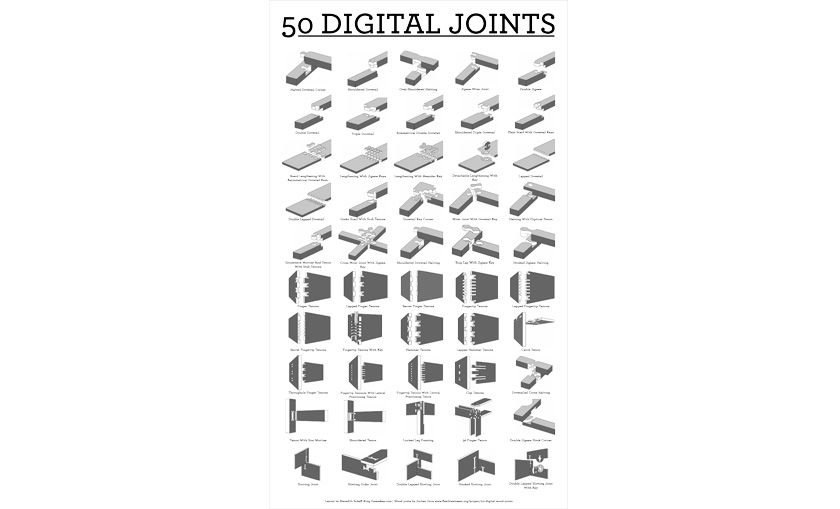
"Poster showing 50 types of Joints from Make Magazine"
You’ll see later on, that the dog bone fillet was the key to fit my pieces, as the CNC endmill doesn’t do well on 90-degree corners.
"Zoomed detail of the 6 mm half-circles that will allow the perpendicular pieces to fit. "
STEP 1: DESIGN OBJECT | TOOLS SHELF
I measured the space and I checked some references before drawing some sketches.
"LEFT: Drawings with measurements. RIGHT: ETSY reference "
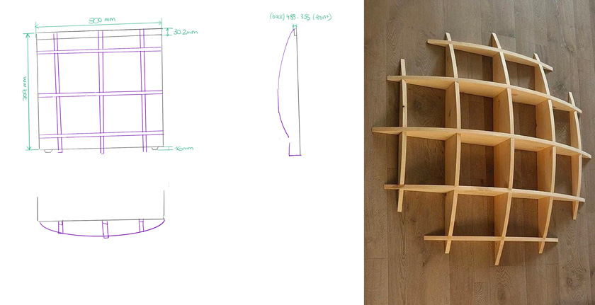
STEP 2: MODEL OBJECT | FUSION 360
I created the model by defining the larger space possible in the middle cells and soft curves on the outer side. As the reference was conceived as a hanging shelf, I had to create some “legs”.
" Fusion 360 Shelf 3D model viewer "
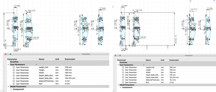
STEP 3: PARAMETRIZE OBJECT | CNC VS LASER CUTTER
I designed first the model for wood with has a material thickness of 15.1 cm. As I wanted to test it first by laser cutting cardboard, I adapted some parameters: material thickness and Kerf.
"Diagram showing CNC workflow, properties and parts. "
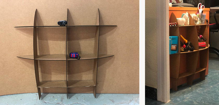
STEP 4: LASER CUT
The process to laser cut and put together the shelf was quite satisfying as it worked so well!.
"Diagram showing CNC workflow, properties and parts. "
STEP 5: TEST PROTOTYPE
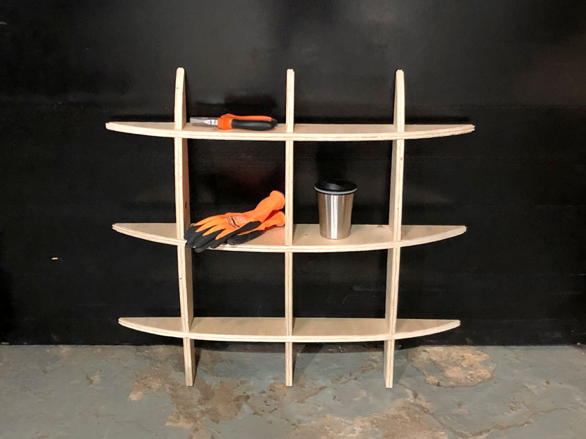
I tested the object both at the lab to show scale ( compared to a measurement tape) and at its place, holding some tools.
"Diagram showing CNC workflow, properties and parts. "
Even though this is not the final product, I wanted to evaluate the process until now as it had some learning outcomes.
WHAT WENT WELL
It helped to fix some bugs: By extruding the pieces and assembling the shelf in the 3D model, I spotted some bugs.
It worked!: I was glad to see that the shelf worked, even structurally already made in cardboard stock (4mm).
WHAT COULD BE BETTER
Test done in a different material: By testing with cardboard, you get a proof of concept, but it doesn’t really help to tune the settings for the CNC. 4mm vs. 15.1 mm.
Time-consuming : By preparing files for two different digital fabrication processes, you end up spending a lot of additional time.
STEP 6: THE REAL THING STARTS | SETTING UP RHINOCAM
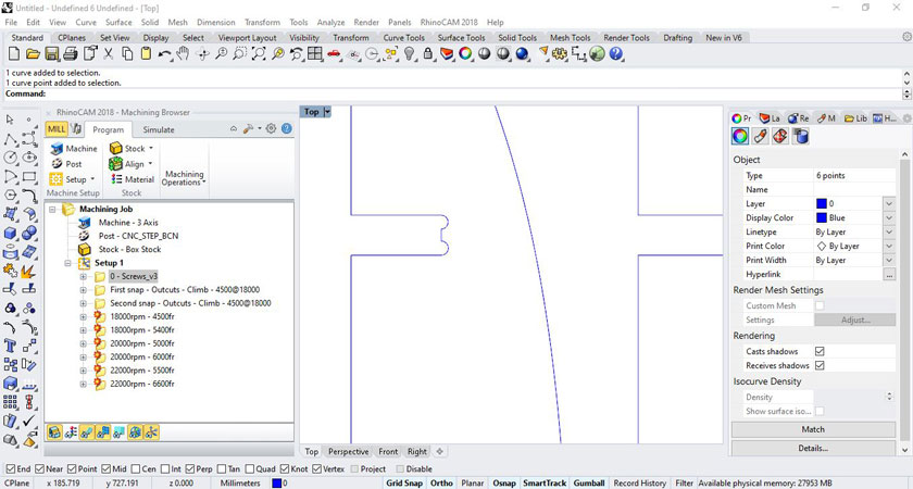
JOINNING CURVES AND ADDING SAFETY ZONE AND SCREWS
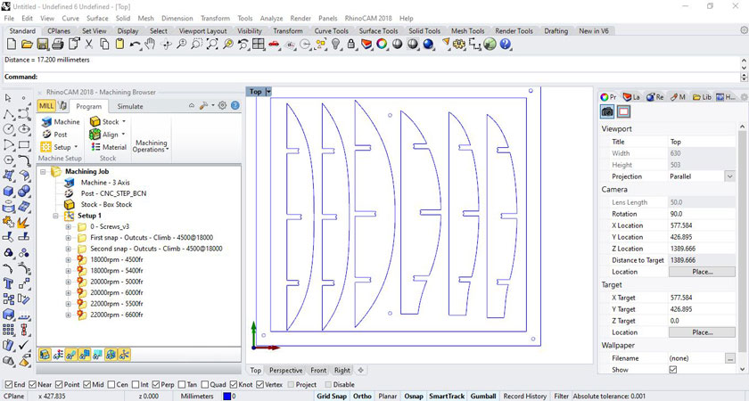
"Image showing blueprint of the pieces ready to be CNC including screws and safety zone."
ADDING DOG BONE FILLET TO HAVE A PERFECT FIT
"Zoomed detail of the 6 mm half-circles that will allow the perpendicular pieces to fit. "
ENGRAVING RHINOCAM SETTINGS FOR CREATING MARKS FOR THE SCREWS.
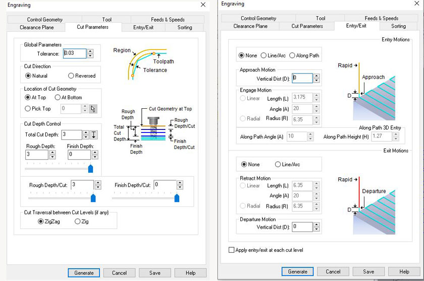
"LEFT: Engraving cut parameters. RIGHT: Entry/Exit engraving parameters."
CHECKING SIMULATIONS
](/2021/labs/barcelona/students/carla-molins/assets/img/week7_22.jpg)
"LEFT: Profiling tool settings. RIGHT: Profiling simulation cut preview. "
PROFILING SETTINGS
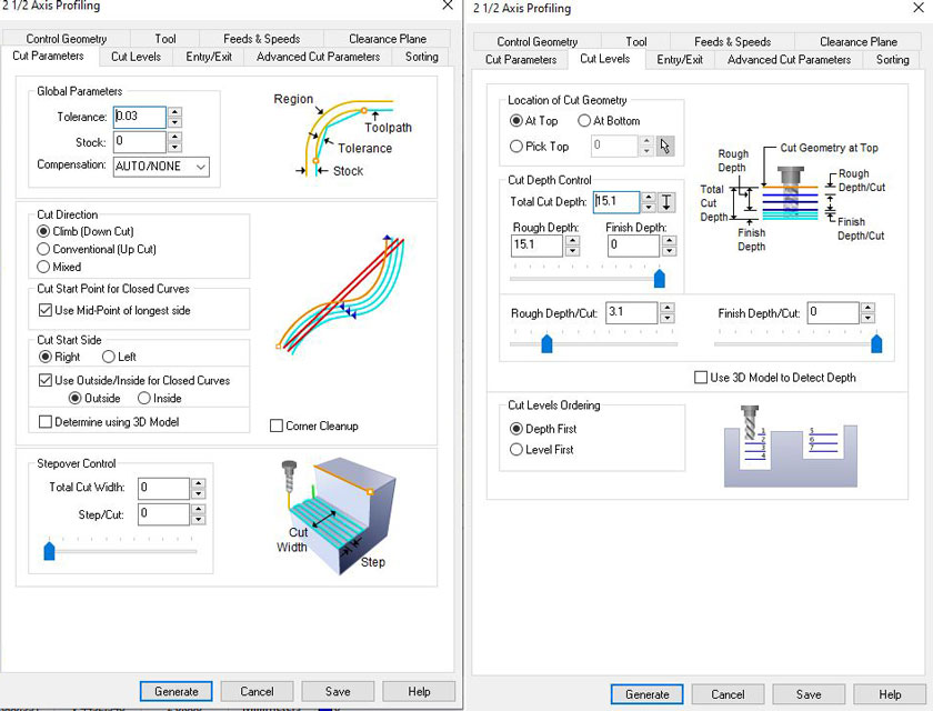
"LEFT: Cut parameters. RIGHT: Cut levels."
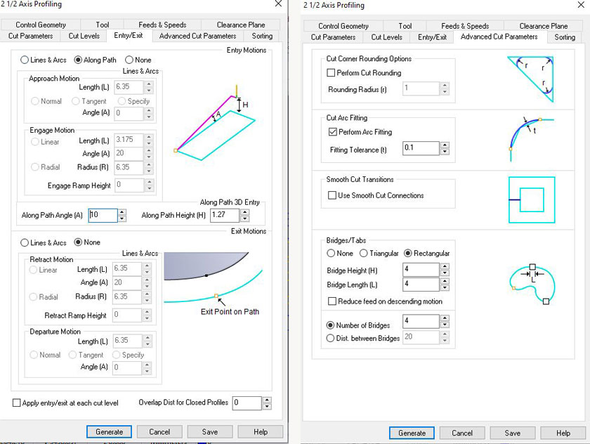
"LEFT: Entry/ Exit. RIGHT: Advanced parameters"
Download Rhino + RhinoCam Setting Files Download Screws Gcode File Download Screws Gcode File
STEP 7: CUTTING TIME!
SETTING HOME X,Y,Z
"LEFT: Homing endmill hardware side. RIGHT: Homing endmill software side."
LOADED FILE & CUTTING
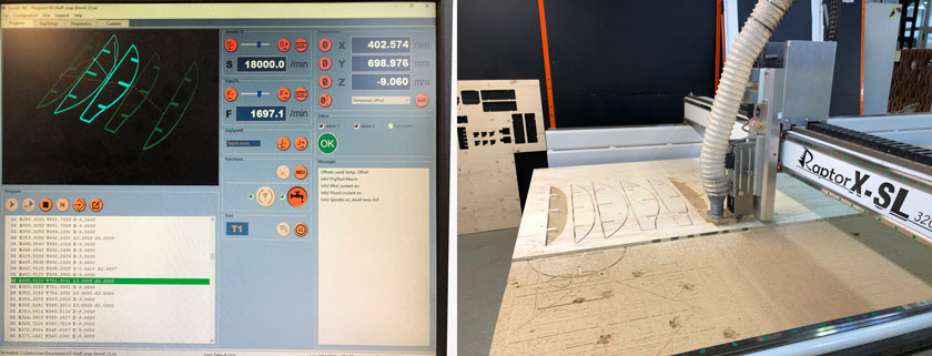
"LEFT: cut preview. RIGHT: CNC cutting the pieces."
"Cutting first piece."
SOMETHING WENT WRONG
There was an error with some curves weren’t properly closed and the machine cutted on the outside. I fixed it with the help of our instructor Josep.
"LEFT: Chisel and Mallet ready to take out the piece. RIGHT: Spotted mistake. "
GOING STRONG!
STEP 8: SANDING TIME
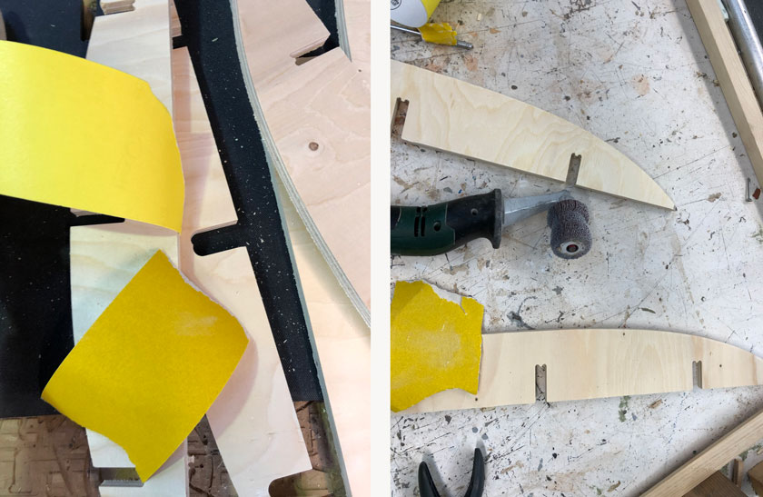
"LEFT: Sanding papers 80 120. RIGHT: Sanding power tool. "
STEP 9: TADAH!
"Gif showing the shelf from pieces to a whole!"
STEP 10: HERO SHOT
"Diagram showing CNC workflow, properties and parts. "
WHAT WENT WELL
Very sturdy: It’s a very robust piece of furniture with no adhesive or screws.
Very nice result: I’m very happy with the result, I’ve never desined a piece of furniture like this.
Learning process: I learned a lot during the process. It was a bit overwhelming, but it will for sure important knowledge to move forward.
WHAT COULD BE BETTER
Way too much sanding: As the joints had just a small tolerance 0.2, it was super tight. If I were to do it again I would go 0.4 maybe.
Brittle material: The material was a bit more brittle than expected, so some edges didn’t get as defined as expected.
Time-consuming : For a 15 min cut it took me more than an hour to set up the machine, secure, and cut. Later on sanding, sanding and sanding..