Machine Design
MACHINCE DESIGN
Intense week, big thoughts!
Assignment
-
Group assignment: actuate and automate your machine.
-
Individual assignment: document the group project and your individual contribution.
This week’s structure was different to other weeks for two reasons, one all the assignment was a group assignment and second there was the easter break in the middle in which the lab was closed.
HOW TO BUILD A MACHINE AS A TEAM
WHAT DO WE WANT TO DO
After some brainstorming it seems we’ve got a plan!
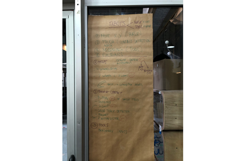
"Planning the group project, Fabots."
We decided to create a common body as a machine using X,Y axis of a CNC shield to control the movement of the body and Z for an attacking tool different for each individual group.
The goal? To have 3 independent bots that could be controlled remotely each one of them having the same body and a different attack piece to defeat the others by “pressing” the button.
BODY
There were lots of efforts to keep all the work and all the progress organized as there were many moving pieces and we needed a common part for everyone before being able to start with the individual part.

"Group Gantt chart"
Other Teams & progress:
Awesome Machine 1 Den, Diego & Gerardo Aweseome Machine 3 Adrien, Lynn & Tarek
In our case this is the link to our repo: Aweseome Machine 2 Carla, Marc & Nil
PROCESS
What we need to do?
- Design a machine that includes mechanism + actuation + automation
- Build the mechanical parts and operate it manually.
- Actuate and automate our machine.
Design a machine that includes mechanism + actuation + automation
DIVIDING GROUP TASKS
- Barduino+ shield kit preparation: Nil, Lynn and Marc
- Barduino+ kit - Soldering: All of us
- Fabblimp firmware + adaptation: ADRIEN
- ESP32 debbuging (TX RX, voltage regulator) : adrien
- PWM(JUMPER) oscillo : adrien
- stepper motor control : Tarek
- Millis : Tarek
- pull-down solving : Carla
- pull-down : tarek
- button : adrien
- Driver calibration: Carla + Nil
- Steper test: Carla+ Nil
- base design: Marc + Diego
- base cutting: Diego + Marc
- Assembling tests: Diego + Nil
- motor support/printing: Gerardo
- button support: Design Diego / Printing Gerardo
- wheels: design and print, Gerardo
- battery housing: Design Diego / printing and soldering , Gerardo
- soldering : All of us
- CNC SHIELD : carla
- Barduino : Adrien
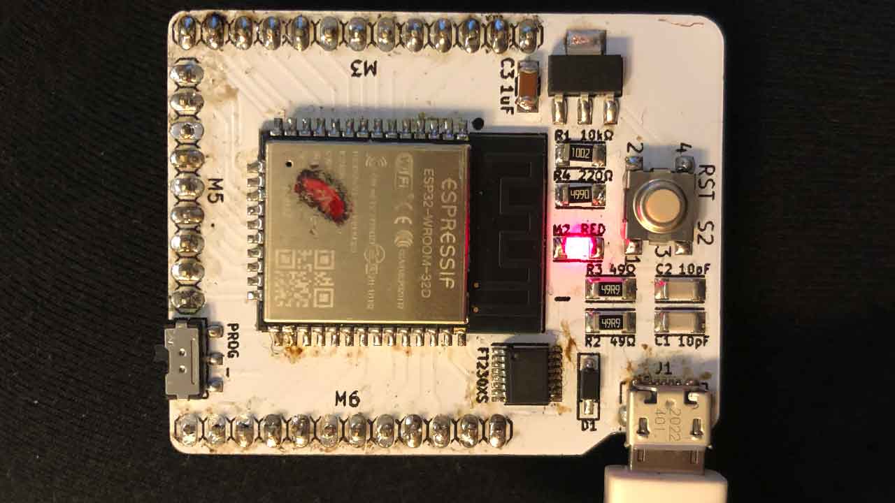
BARDUINO
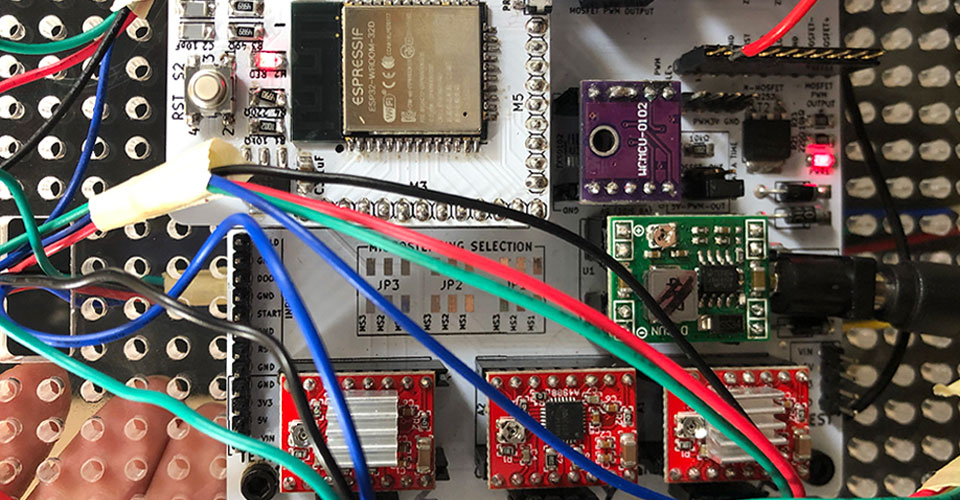
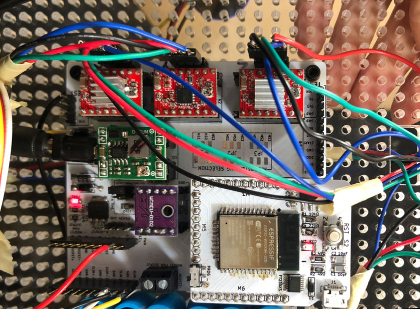
CNC SHIELD
"Assembled CNC shield including the Barduino, a voltage regulator, and 3 motor drivers."
MOTOR AND THE 3D PRINTED BASE
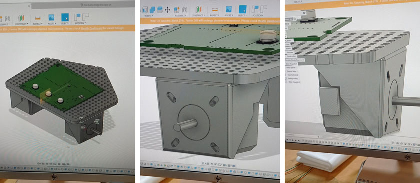
"LEFT: Base Fusion model version 1: MIDDLE: Motor's supports. RIGHT: Motor's support detail."
BATTERY CASE
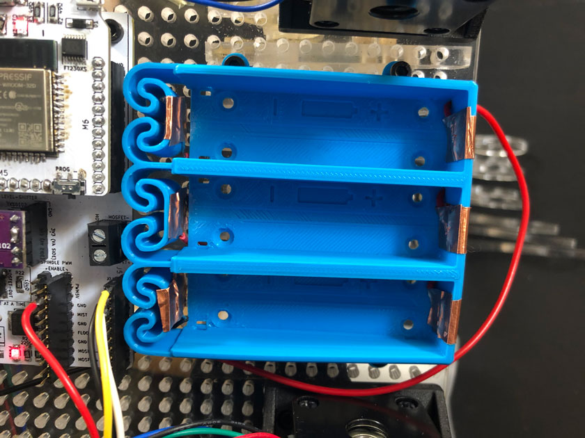
"3d printed battery case with copper tape contacts attached to the base."
BASE
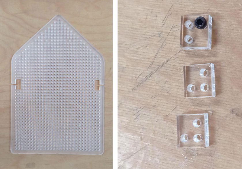
"LEFT: Acrylic laser cut base including wire cavities.RIGHT: Screws fitting tests. "
Laser cutter files for the base
MOTORS
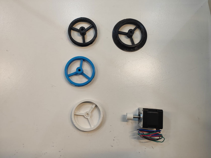
"3d printed wheels for the bot, multiple designs."
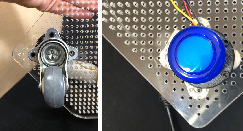
BUTTON
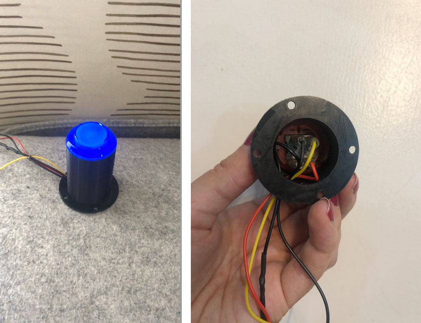
"LEFT: Mounted soldered button on the 3d printed support. RIGHT: inner part of the button."
ALL TOGETHER
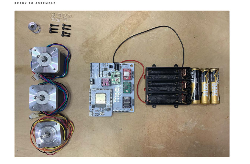
"Setup ready to put together with all components."
MY CONTRIBUTION TO THE BODY (CLASS PROJECT)
MAKING THE FABOT GROUPS
I proposed to use a randomizer to create 3 groups of 3 people for the local students at Barcelona.
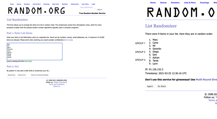
"Group Randomizer"
HOW TO BARDUINO + CNC SHIELD
Find here the instructions:
Things Read to setup your Barduino + CNC shield
Grbl_Esp32 ino + all libraries from this repo; Documentation for the motor driver
Barduino
Barduino Fablab Bcn site; Link to the version we used, Barduino 2.2
WHY? Interface FTDI-USB* Fabbable Yes CNC Shield Compatible Yes
Needed Libraries
Things to do to Use the CNC shield + Barduino
1- Download or Clone this repo
2- Copy this two libraries: ESP32SSDP + arduinoWebSockets from the libraries folder on the Firmware libraries folder to your Arduino Library folder. Mine is on Documents/Arduino/Libraries.
3- Install Board manager for ESP32 —> Arduino —> Preferences
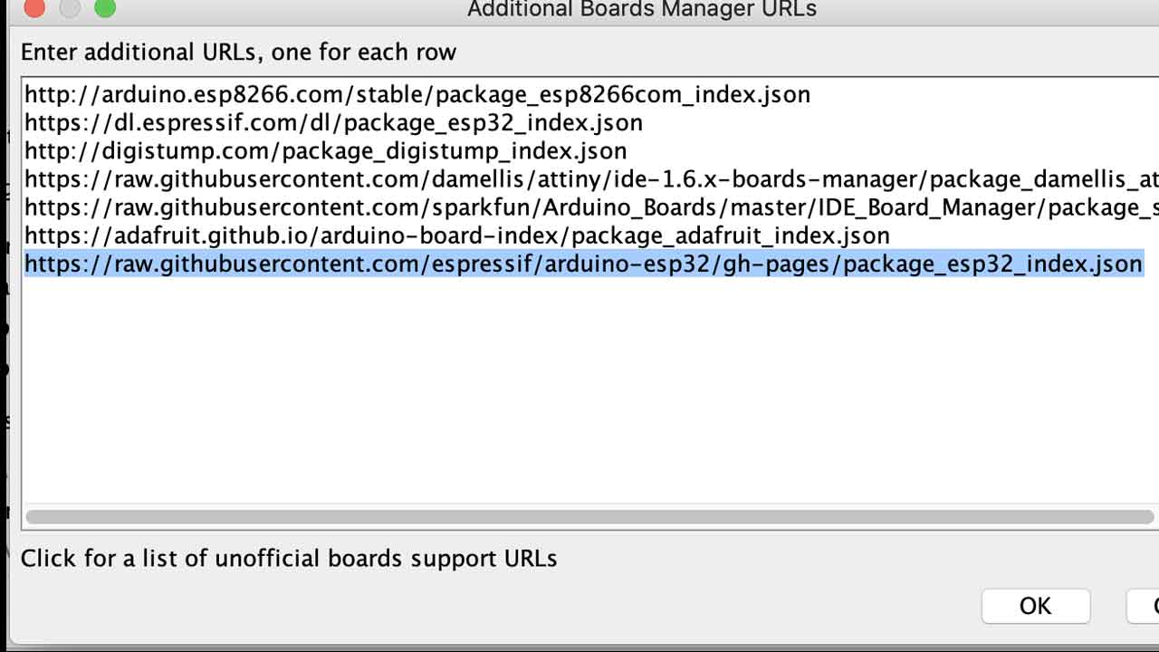
4 - Install ESP32 Espressif on Board Manager
5- Reading installations instructions from the Six Pack milling machine:
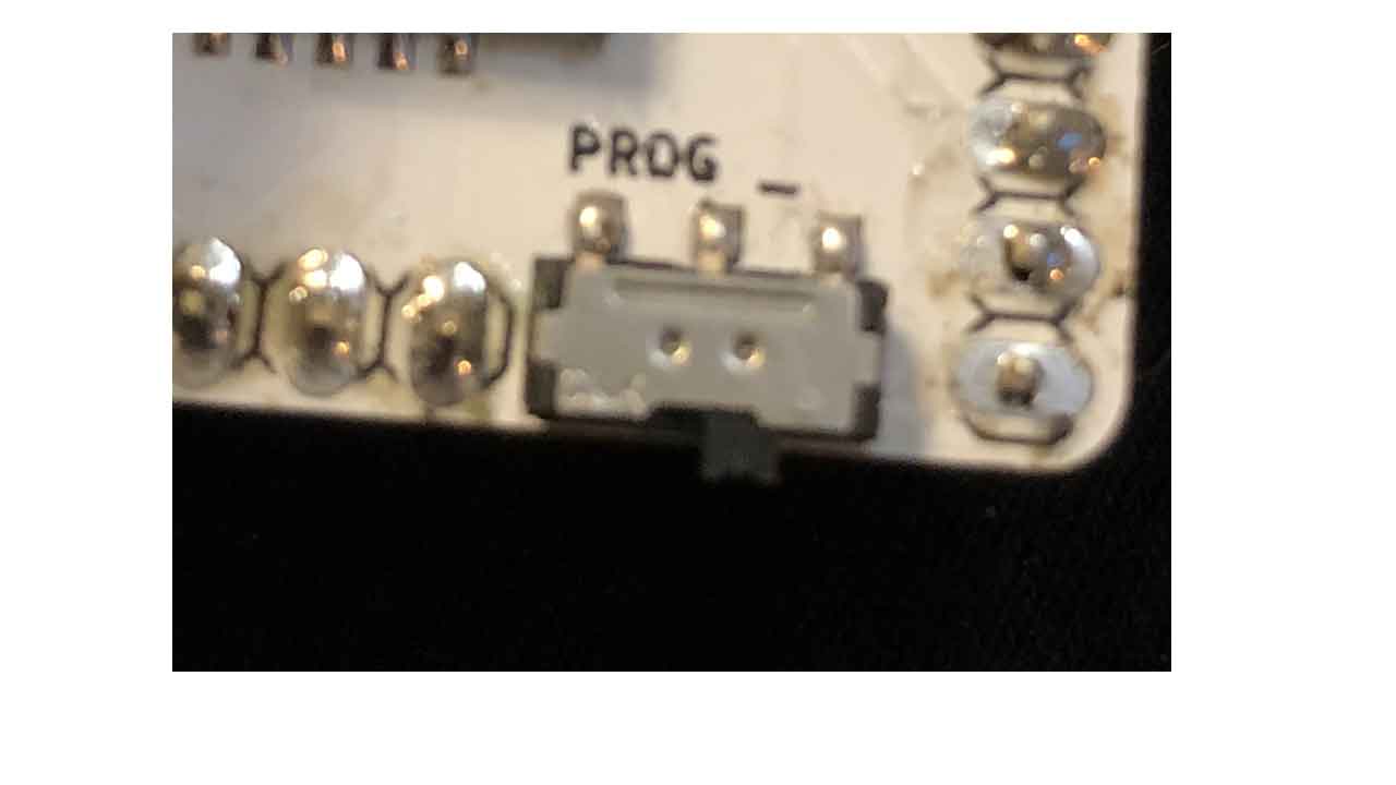
Before 6 - Make sure that before you connect the board the switch is on programming mode.
6- Original Grbl documentation says to remove the barduino board from the shield to program the firmware to prevent any possible damage to the shield. Connect the board:
7- select board. ESP32 - dev Module
8- change Partition scheme to Minimal SPIFFS
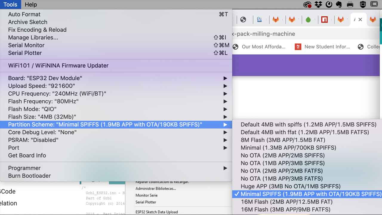
9- Compile Firmware Arduino File - it will take a while depending on the machine.
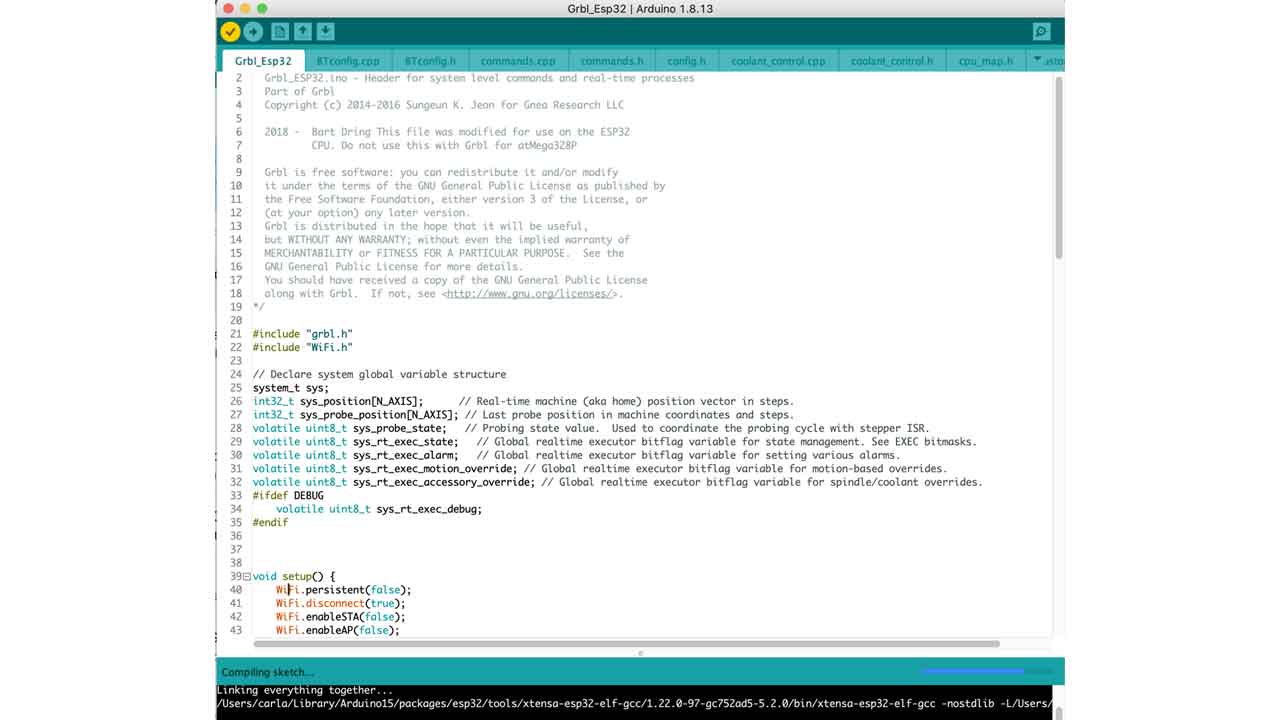
10 - Upload the code
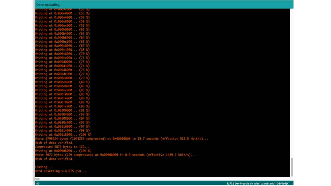
11 - Disconnect the board.
12- Change the switch to Execution Mode
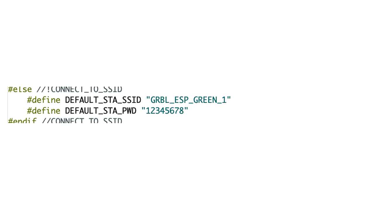
13 - Check for the ESP32 wifi connection. Select Wificonfig.h file to see the Wifi connection details or check screenshot here:
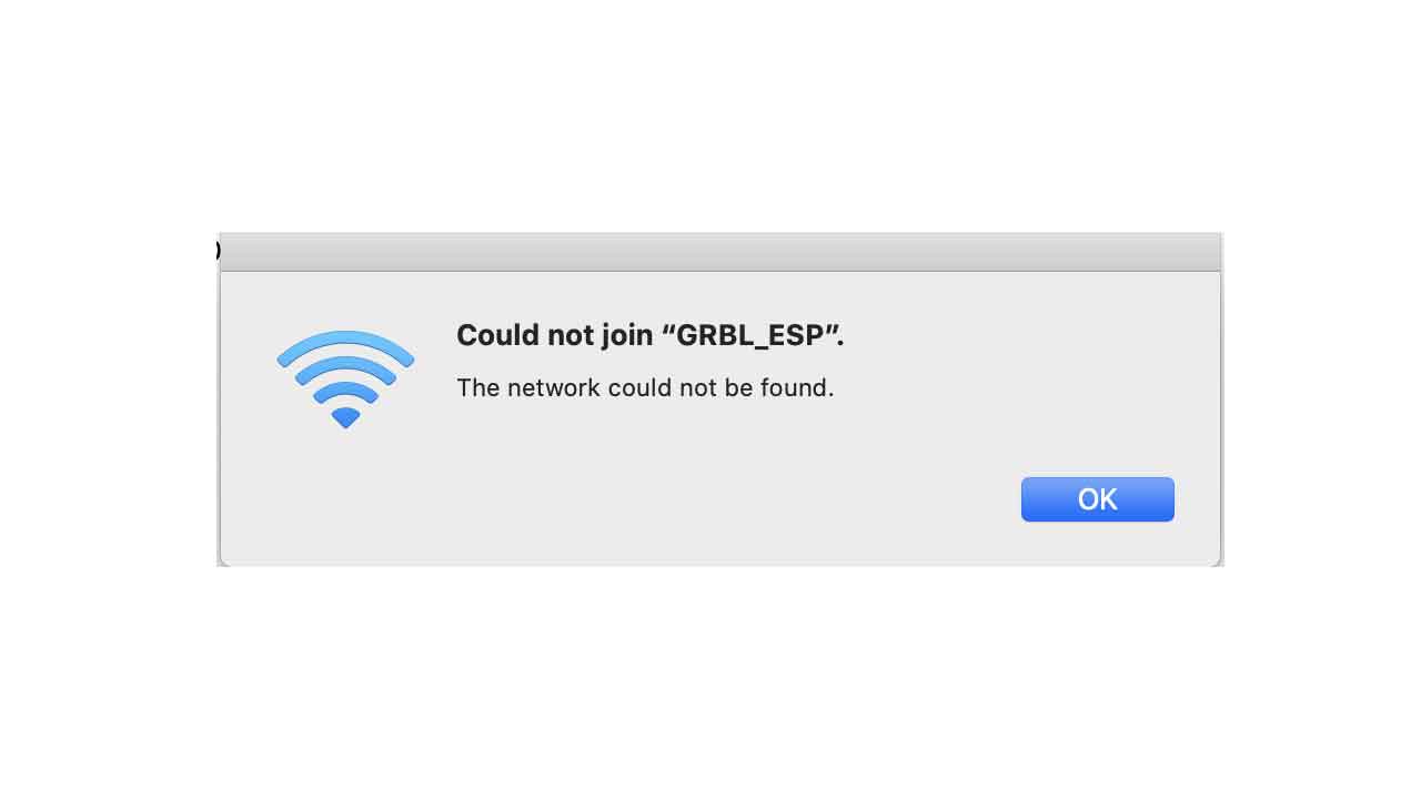
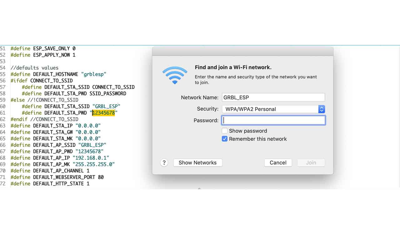 If you try to do it on programming mode, it won’t work:
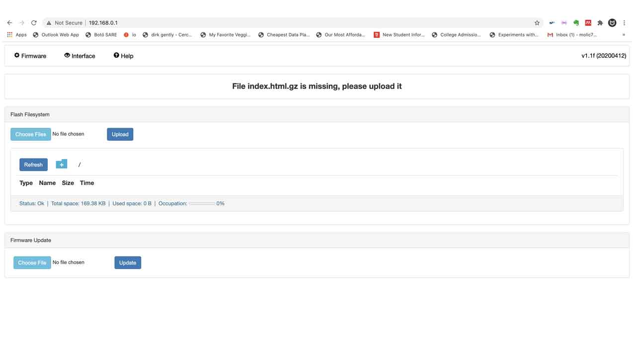
14 — This is the page that pops-up on MacOS (also probably on Windows, too). It will show you the main website of the board. As it’s not a fully functional browser, close it.
Using your browser of preference, visit 192.168.0.1. Make sure you are still connected to the wireless network GRBL_ESP.
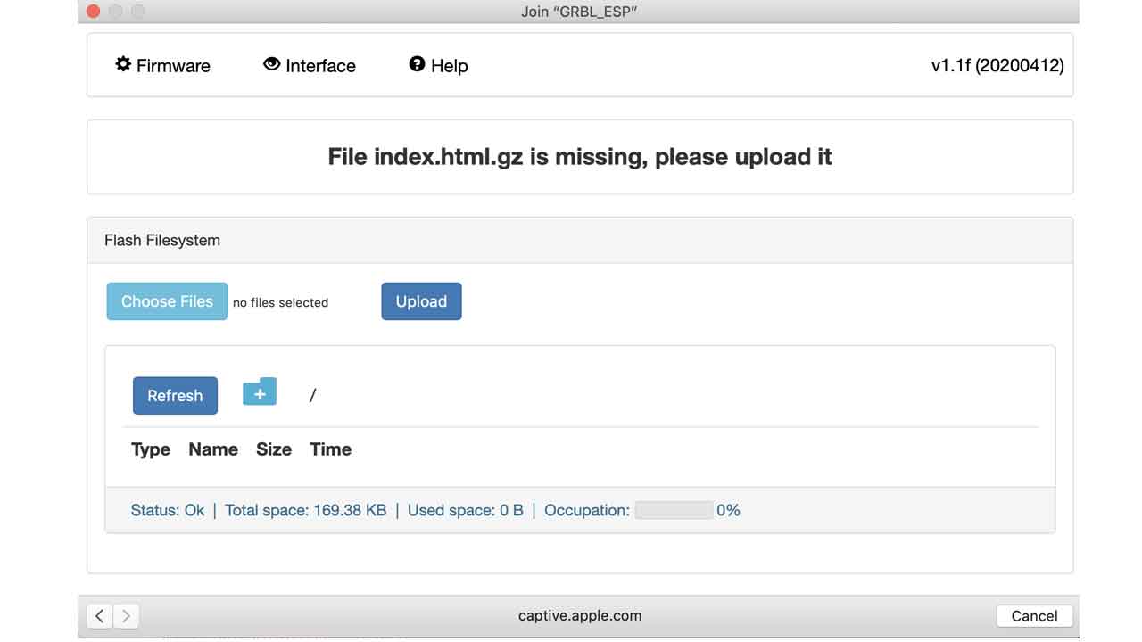
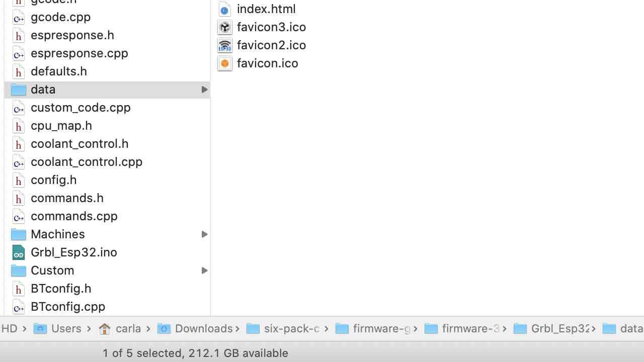
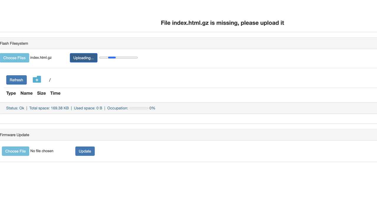
15- We need to upload the index.html.gz file from the data folder that was on the firmware files. Thanks to Tue and David from 2020 Barcelona Fabacademy who had an awesome documentation:
16- After finding the file —> Go to 192.168.0.1
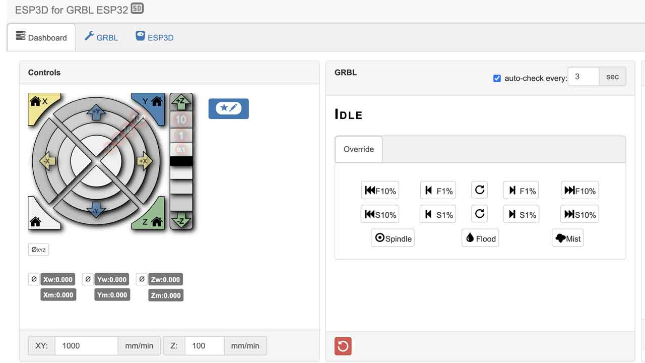
17- It will say Uploaded 100% and a new button will appear “Go to ESP3D interface”. Click on it and it will take you to the motor control interface.
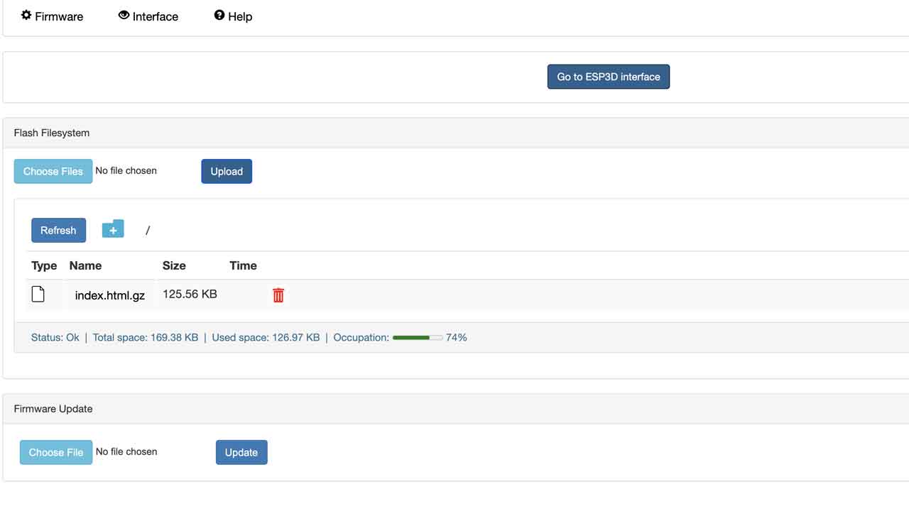
18- This is the cnc shield interface. Before pressing anything let’s go back to hardawre.
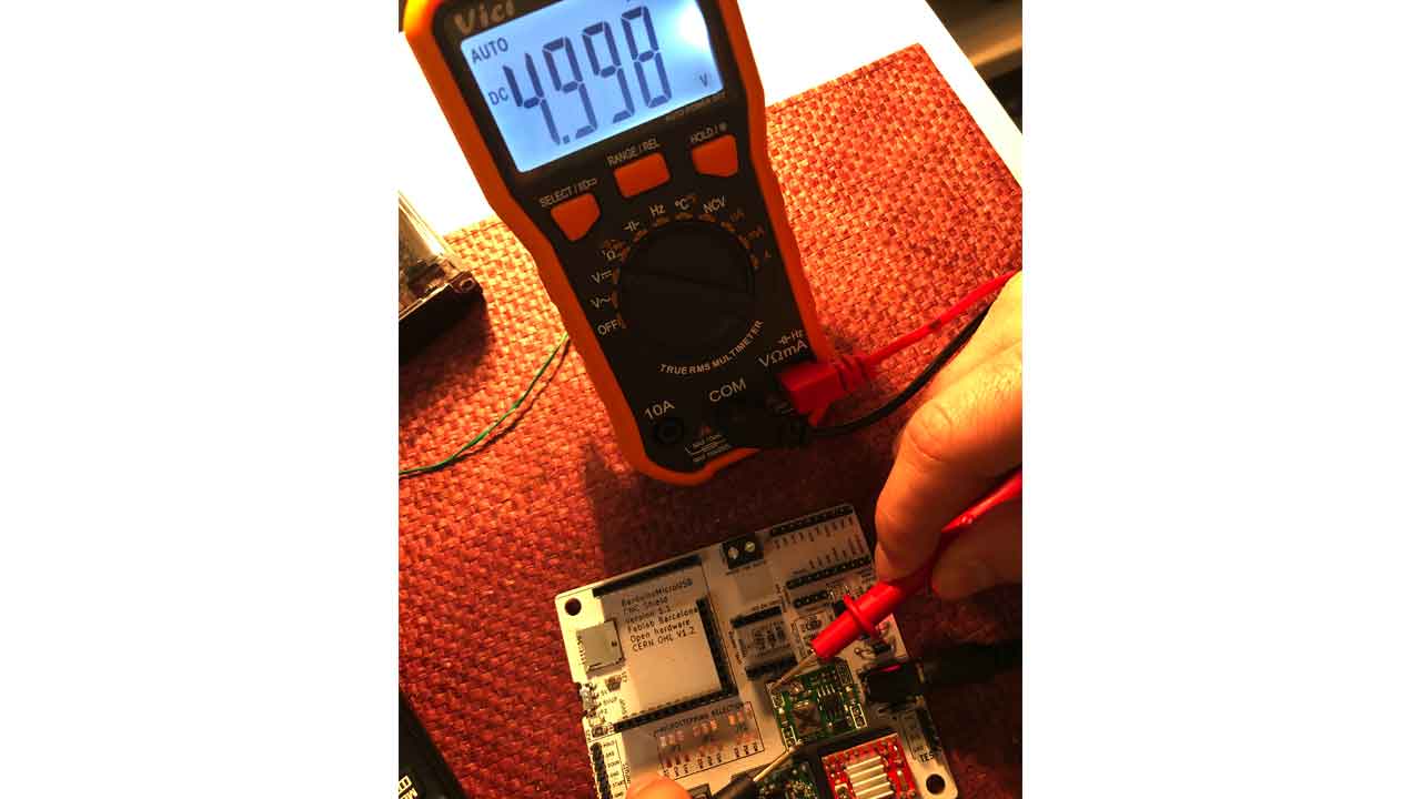
19 — Check the Voltage of the Voltage regulator.
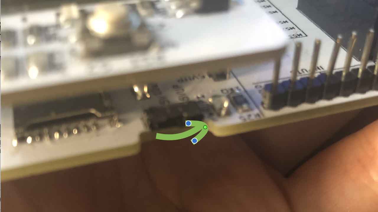
20- - Now you can connect the Barduino to the driver board. Move the switch under the board to 5VUP before mounting the Barduino to the header pins.
21 - WARNING - Time to setup the current limit for each motor driver —> Watch this video and continue on next step.
22- As you’ll see you need to check the specs for your motor, meaning NEMA 11, 14, & 17 might have differents specs. If we setup each motor driver according to its motor they won’t be interchangeable ( unless it’s the same model) or the motor could get damaged
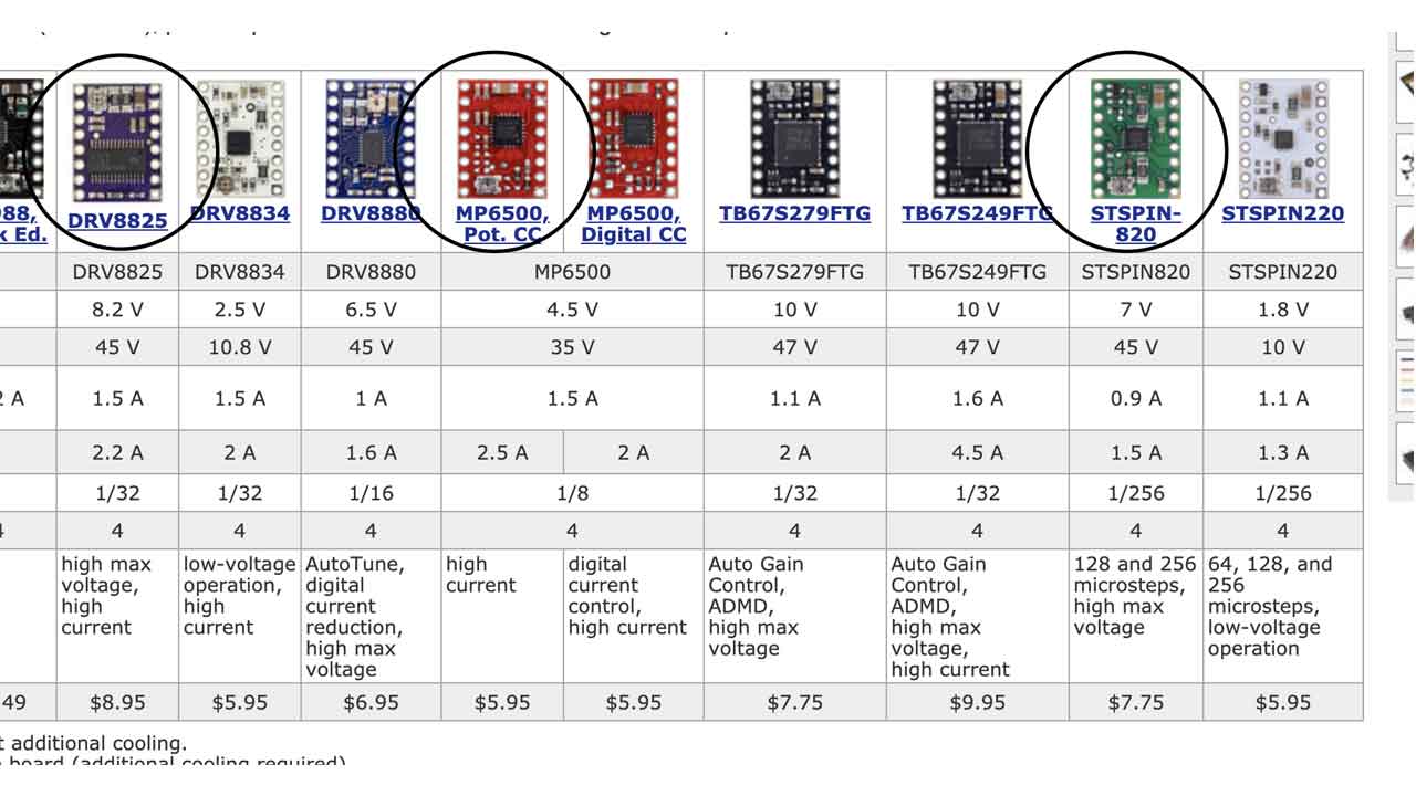
22A Purple one - Polulu driver DRV8825. The other two drivers look like knockouts of the other polulu models. I couldn’t find the specs
23- Not all have the same pinout orientation. —> Check for GND to match the shield .
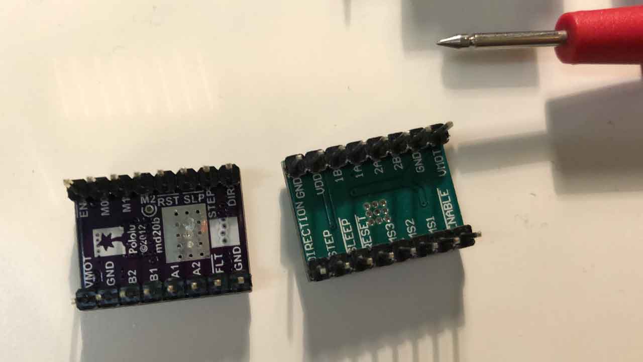
For the NEMA 14- SY35ST36 —> The Voltage measured from the screw or VREF to GND needs to be around 500mV. Check this
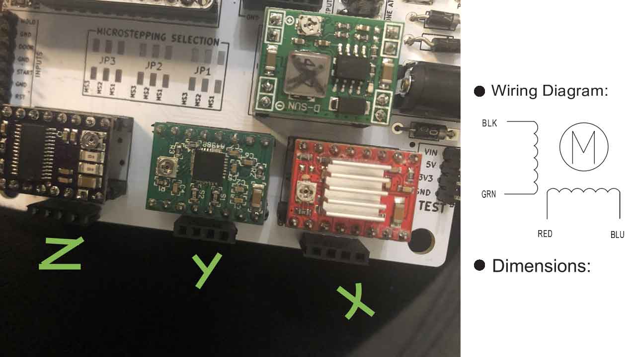
24- Time to connect the motor- Make sure that the power supply is desconnected. I connected the wires according the wiring diagram on the motor’s datasheet —> Black, green, red and blue.
25- Time to connect to the GRBL-ESP http://192.168.0.1/
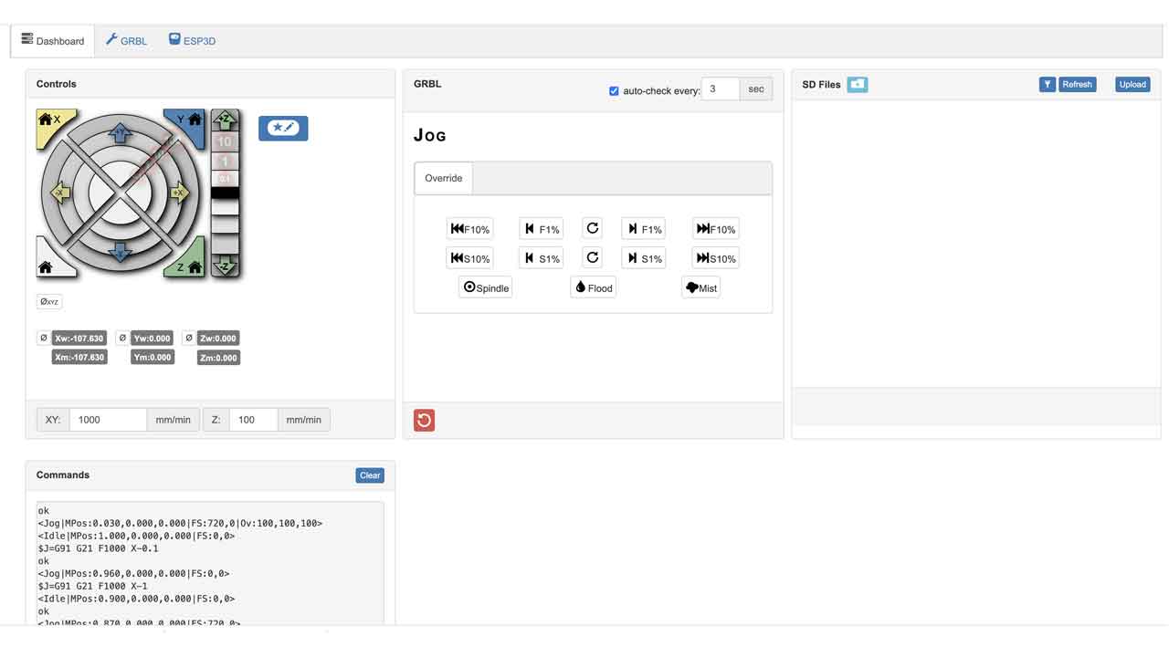
When sending the commands the motors moves. Not super consistently, as it seems that wiring is a bit flickery. Wiring should be checked, everything else seems to be working.
26- Last: SET SSID for each Barduino
And this is for setting up the Barduino + CNC shield. There are many steps, but with this instructions, all groups were able to setup their boards.
Assembling a Barduino 2.2.1 Resource
SETTING UP MOTORS + MOTOR DRIVERS (with NIL)
BUTTON
After fixing the PWM with Adrien, I was able to assemble all the buttons inside their supports and with proper wiring.
"LEFT: Mounted soldered button on the 3d printed support. RIGHT: inner part of the button."
"Testing button assembly."
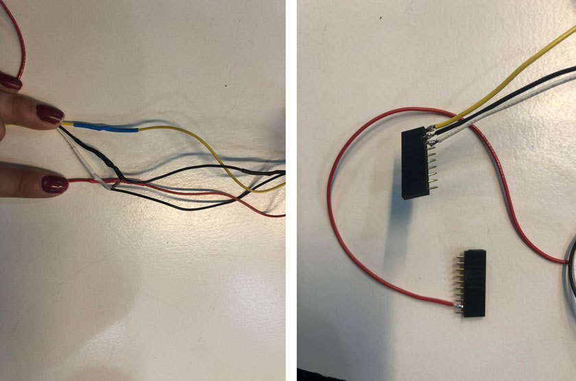
"LEFT: Wiring buttons including 10k resistor in between yLim & ground. RIGHT: Soldering wiring buttons on the headers."
INTERFACING CODE
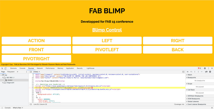
"Screenshot showing the interface popping up an error, javascript missing."
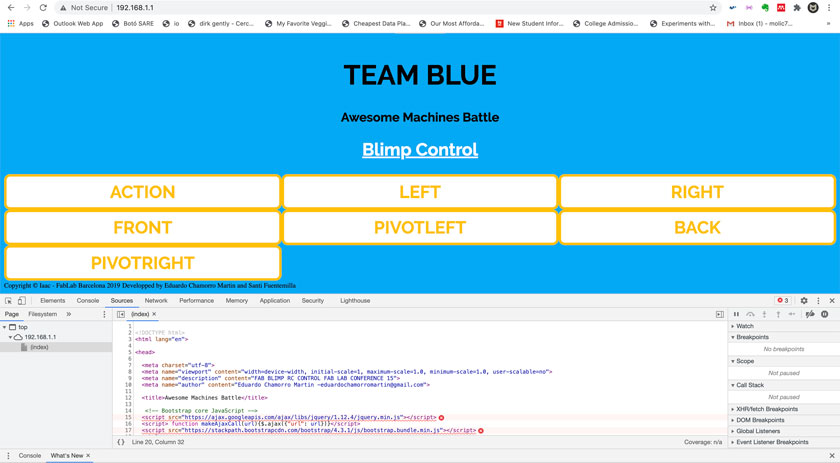
"Interface customized for Team Blue (ours)."
When working with the Interface’s code I realized that the ESP32 wasn’t accessing properly the javascript libraries, so after getting Edu’s help we have now some changes so the ESP 32 connects to Iaac’s network and offers an IP address to access the interface.
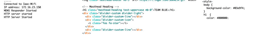
"LEFT: IP to connect to the ESP32 to control de Fabot. MIDDLE: screenshot showing the customized Title for the app. RIGHT: custimized color css."
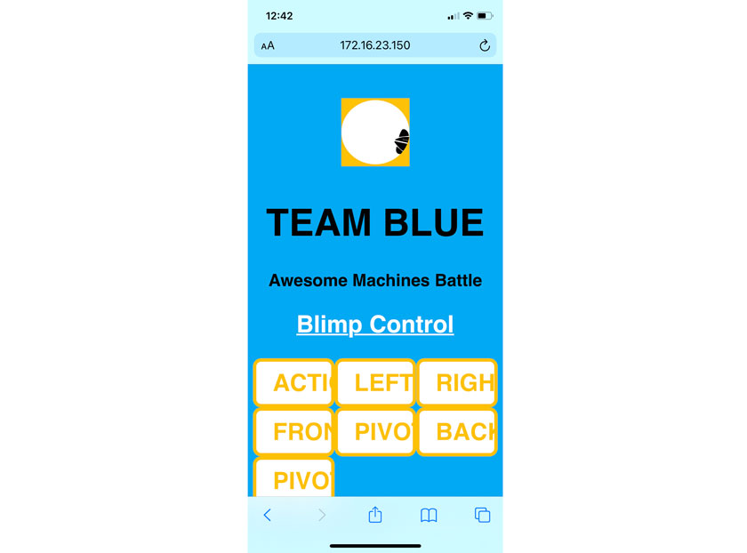
"Interface screenshot from an Iphone cellphone."
TOOL
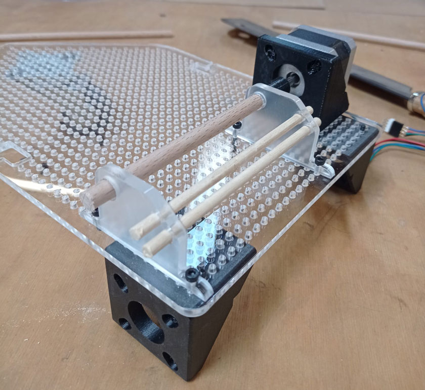
The tool that our team designed consists of a stepper motor crankshaft that moves different elongated pieces in a sequence. The idea is that on action the different “fingers” will aim for the oponents button from a wider range.
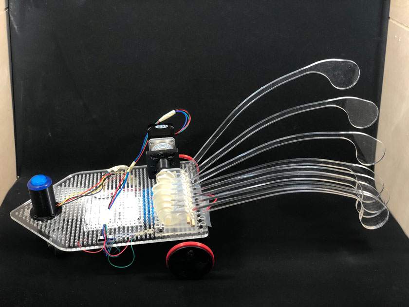
"This is FABYOU! The crankshaft ready to say hi."
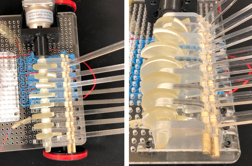
"Crankshaft's detail."
"Other details"
On our Team we worked together to define how the tool was going to be and how to build it.
Marc was in charge of modelling the base for all the Teams and in addition he created a 3D model and simluarion of our tool. He also laser cut the bases and pieces for the crankshaft, 3D printed the motor supports.
Nil was in charge of the crankshaft and making sure that all components coming from other class members were ready for us to build our Fabot. That included the battery pack, and recharging batteries.
Carla (me) was in charge of the electronics and the interface. I created this tutorial document to help my peers to assemble and setup their boards. HOW TO BARDUINO + CNC SHIELD
SKETCHES
Full description here: Aweseome Machine 2
PROTOTYPE
Full description here: Aweseome Machine 2
BUILDING THE FINAL VERSION
LASER CUTTING
"Failed SLA printing of the Vehicle Crankshaft with Formlabs"
SLA PRINTING
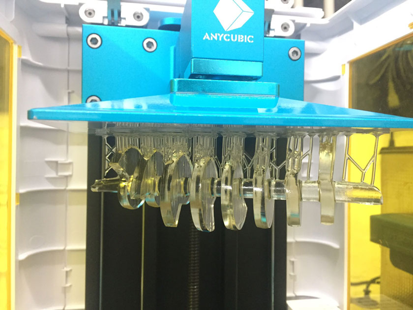
"SLA printing of the Vehicle Crankshaft with Anycubic."
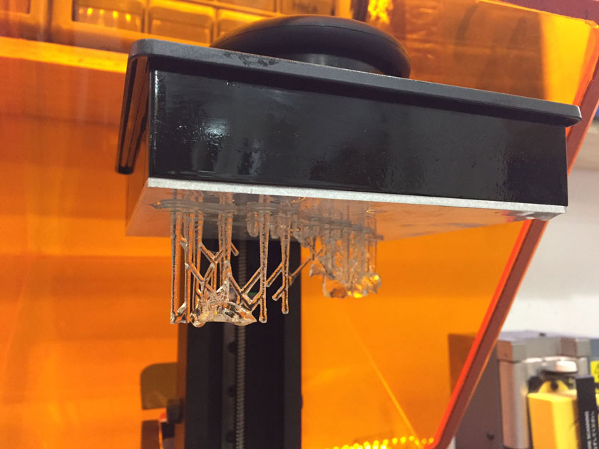
"Failed SLA printing of the Vehicle Crankshaft with Formlabs"
MANUAL OPERATION MACHINE
MOTOR WITHOUT ENOUGH FOR THE CRANKSHAFT
YAY, IT WORKS!
MY CONTRIBUTION TO MY TEAM
ESP 32 INTERFACE FOR BARDUINO + CNC SHIELD
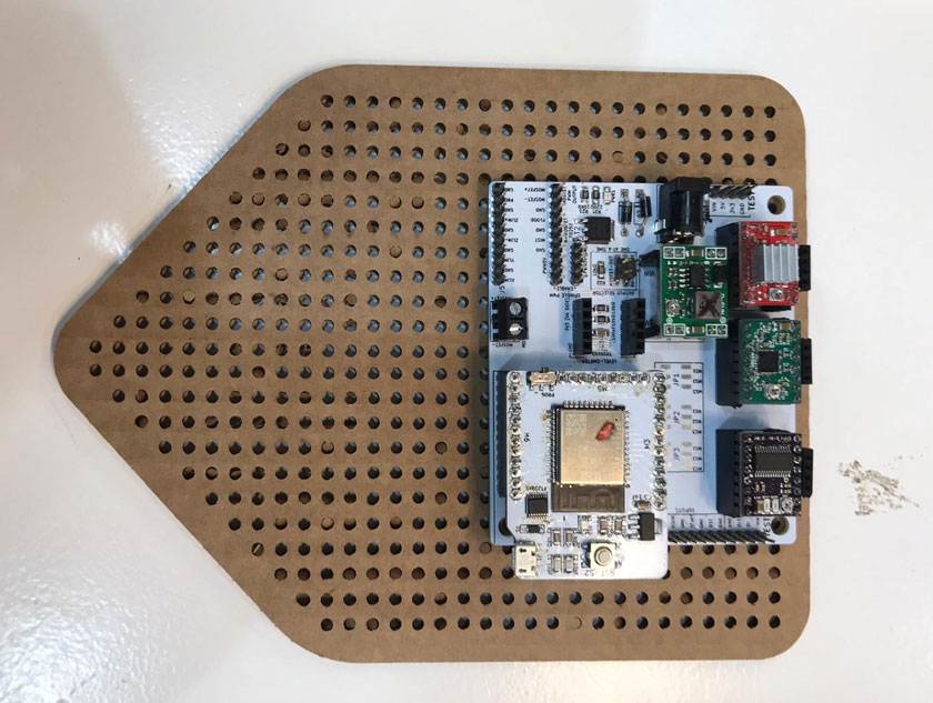
I was working on the core of the bot, the Barduino + CNC shield, Interface & Arduino code. So in the end I ended up programming the tool as well as I was the one who was more familiar with coding.
"The Brains of the FABYOU"
Carla’s instructions to setup Barduino + CNC shield controlling motor drivers
FINAL BOT
Our idea was to create a tool that had a wide range of contact points to defeat the oponents. We created a trickier mechanism than we invisioned but it end up working!
Our bot ended up being a bit heavier than expected, but ready to take a round.
WHAT WENT WELL
We had fun & struggled because of the challenge: It was the most ambitious project we developed so far and yet the one it felt we had less time to produce because of the easter break.
A lot: I feel I was able to learn a lot while troubleshooting as well as from working with my peers.
WHAT COULD BE BETTER
I worked on what knew the most rather that on what I wanted to learn:Because of time constraints we decided to divide taks according our skillset which makes total sense. However I couldn’t work on the parts that I was hoping to work to learn for my final project.
Timing I feel that if it would have been a regular week me might have gotten further.