8. Embedded programming
This week our task was to program our board to do something, with as many different programming languages and programming environments as possible. We also need a read microcontroller datasheet. I chose ATTiny85 because in a previous weeks I designed a pcb around that microcontroller. For the group assignment we had to compare the performance and development workflows for other architectures.
Individual assignment
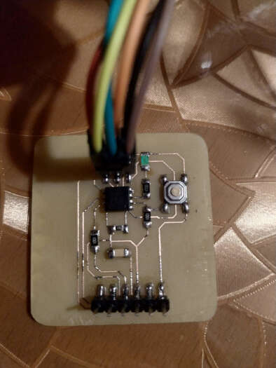
This is my board that I made in Electronic design week. I downloaded datasheet for ATtiny85 from Microchip site.
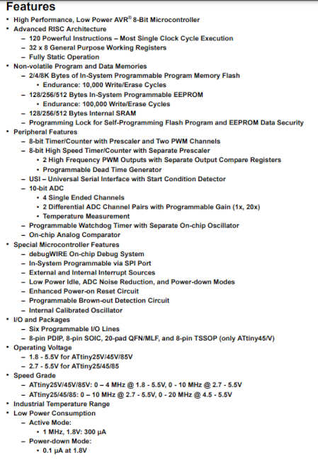
The first thing I saw was that ATTiny25/45/85 were very similar. They differ in memory size (flash memory, EEPROM, SRAM). Tiny85 has 8KB of programmable flash memory, 512B EEPROM and 512B of SRAM memory. You can see in a features section bellow.
ATTiny85 comes in PDIP and SOIC package with pinout displayed in the following picture. When I design a pcb in previous weeks I had to look at the pinouts to see which pins are free.
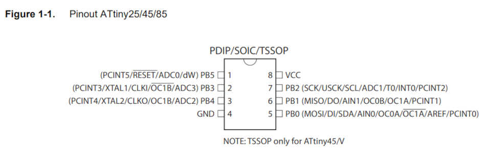
This is a short explanation of pins:
- VCC - Supply voltage
- GND - Ground
- Port B (PB5: PB0) - Port B is a 6-bit bi-directional I / O port with internal pull-up resistors (selected for each bit).
- RESET - Reset input. A low level on this pin for longer than the minimum pulse length will generate a reset.
The ATtiny25/45/85 is a low-power CMOS 8-bit microcontroller based on the AVR enhanced RISC architecture. Block diagram can be seen here
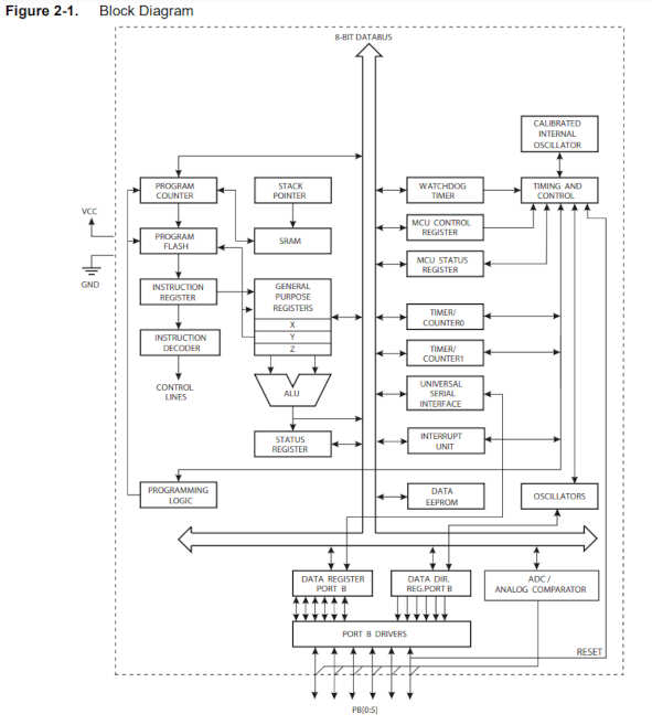
The resulting architecture is more code efficient while achieving throughputs up to ten times faster than conventional CISC microcontrollers. The ATtiny85 provides the following features: 8K bytes of In-System Programmable Flash, 512 bytes EEPROM, 256 bytes SRAM, 6 general purpose I / O lines, 32 general purpose working registers, one 8-bit Timer / Counter with compare modes, one 8-bit high speed Timer / Counter, Universal Serial Interface, Internal and External Interrupts, a 4-channel, 10-bit ADC, a programmable Watchdog Timer with internal Oscillator, and three software selectable power saving modes.
In the following picture you can see a block diagram of the AVR Architecture.
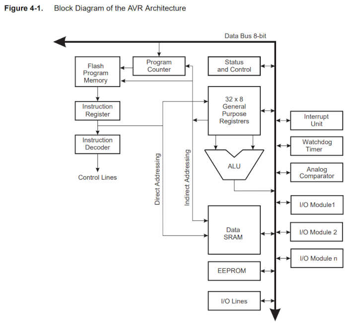
In order to maximize performance and parallelism, the AVR uses a Harvard architecture - with separate memories and buses for program and data. We can write values directly to the register, for example PORTB and DDRB registers. With these registers we set the input or output of the corresponding pin and we can set it high or low.
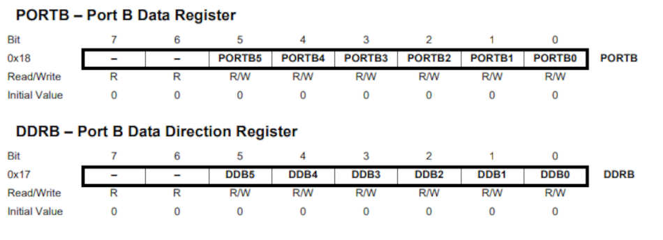
I will use these registers later when I program in Microchip Studio. After studying the datasheet, next was programming. First I decided to try Arduino hardware and software. I decided to use the Arduino Uno as a programmer. I followed this link. I added ATTiny support to Arduino IDE under file-> preference and pasted link that I found in link above.
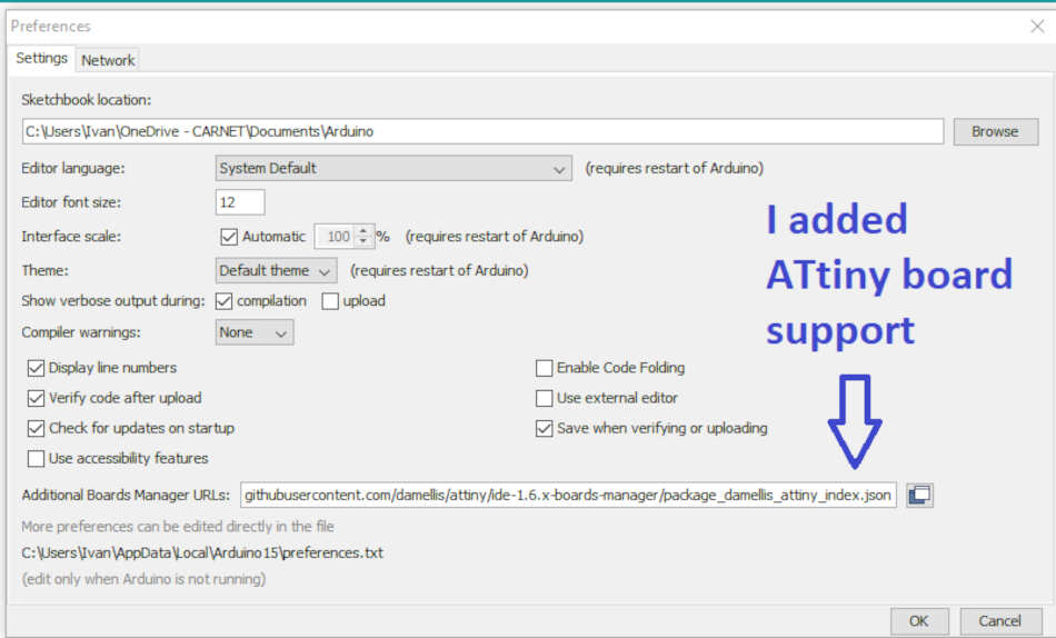
From the board manager I installed ATTiny support for 45/85 and 44/84 microcontroller. Now it’s time to connect my pcb with arduino through ISP header. SPI communication on ATTiny85 is part of Universal Serial Interface (USI). USI offers Synchronous data transfer and more about USI that can be found in datasheet. I have to set up the Arduino Uno as a programmer. I loaded the ArduinoISP sketch. Now he is a programmer and I can program ATTiny85. From tools menu I set:
- Board: ATTiny25 / 45/85
- Processor: ATTiny85
- clock: Internal 8MHz
- Port: COM4
- Programmer: Arduino as ISP
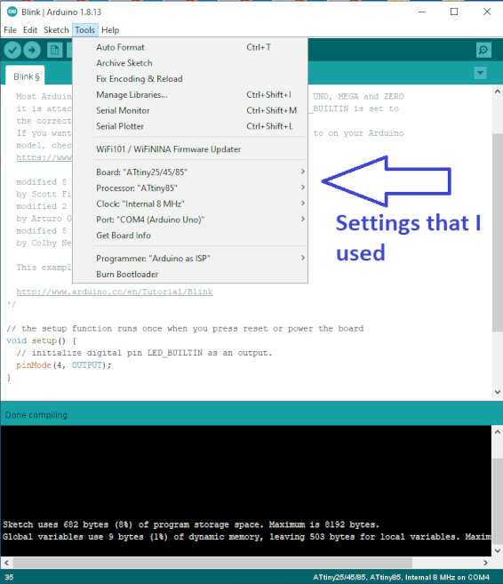
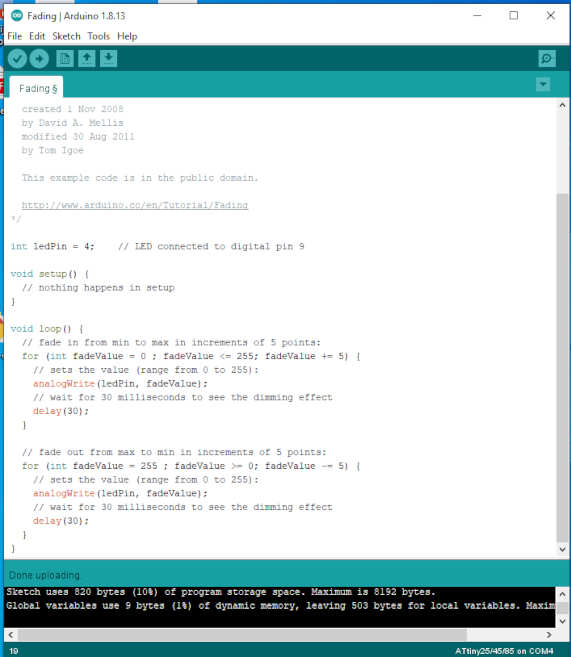
Then I go to compile and upload. It works. I tried three different sketches, blink led, fading led and push button led.
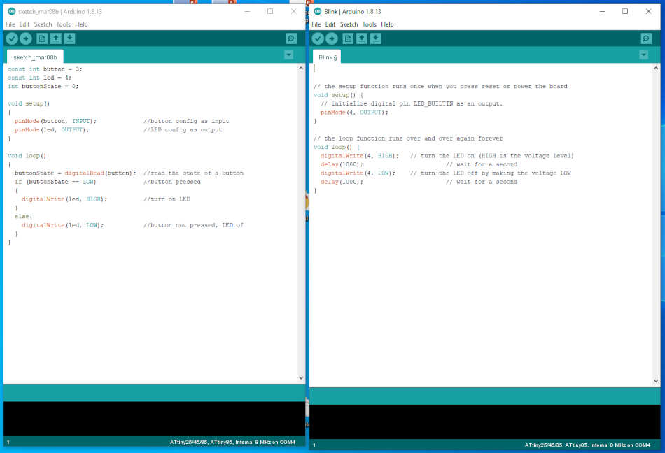
Push button LED
Fading LED
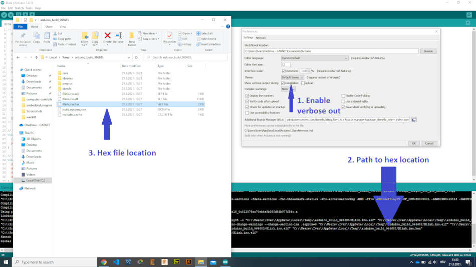
After that I tried avrdude and programming from command line. Avrdude comes with arduino so I did not need to install it separately. In order avrdude to work I added a path to avrdude in environment variables. I need a hex file to upload it on microcontroller. I found path to hex file in arduino. I copied hex file to avrdude directory.
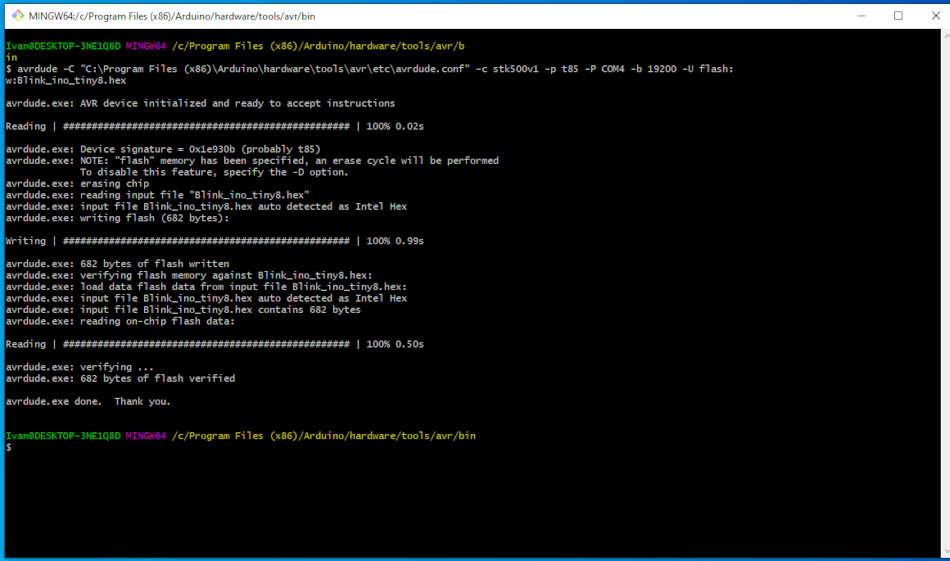
I found this page which explains all the avrdude parameters. So after I set the configuration file, COM port, programmer, microcontroller and baud rate I press enter. I kept getting port type errors not correct, programmer not correct… I decided to use git bash with the same parameters instead of command prompt. Success.
Next IDE to try is Microchip Studio. Microchip Studio is an Integrated Development Environment (IDE) for developing and debugging AVR® and SAM microcontroller applications. It merges all of the great features and functionality of Atmel Studio into Microchip’s well-supported portfolio of development tools to give you a seamless and easy-to-use environment for writing, building and debugging your applications written in C / C ++ or assembly code.
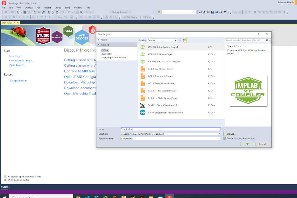
When I opened Microchip studio I go to file-> new project. I chose AVR XC8 C Application Project.
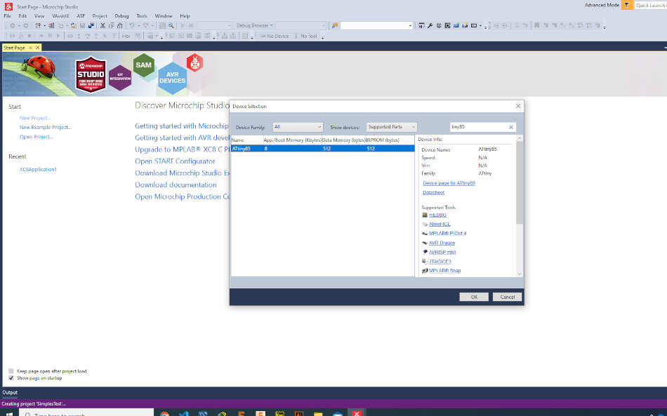
From the device selection I chose tiny85. I wrote a simple code by writing to I/O registers decribed before in datasheet. I needed to import a delay library.
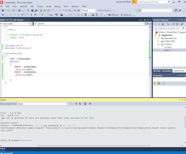
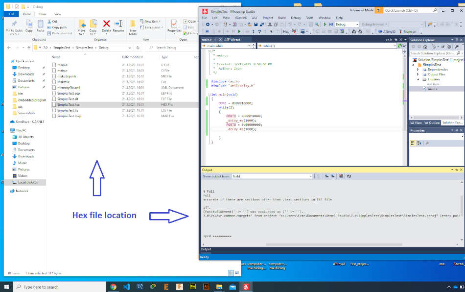
Than I go to build solution, there were no errors. To upoad it I used avrdude.
Group Assignment
For the group assignment we had to compare the performance and development workflows for other architects. I have microbit and Discovery board from ST.
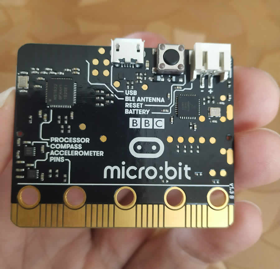
Microbit
The Micro Bit is an open source hardware ARM-based embedded system designed by the BBC for use in computer education in the United Kingdom. The device is described as half the size of a credit card and has an ARM Cortex-M0 processor, accelerometer and magnetometer sensors, Bluetooth and USB connectivity, a display consisting of 25 LEDs, two programmable buttons, and can be powered by either USB or an external battery pack. The device inputs and outputs are through five ring connectors that form part of a larger 25-pin edge connector.
Microbit can be programmed in several ways, code blocks, Python and JavaScript. I went to (https://makecode.microbit.org/) and chose javascript.
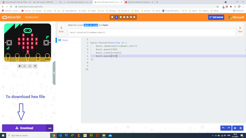
I made a flashing hearth. There is a simulator on the page with which we can test the written code. To download a hex code we go to download button.
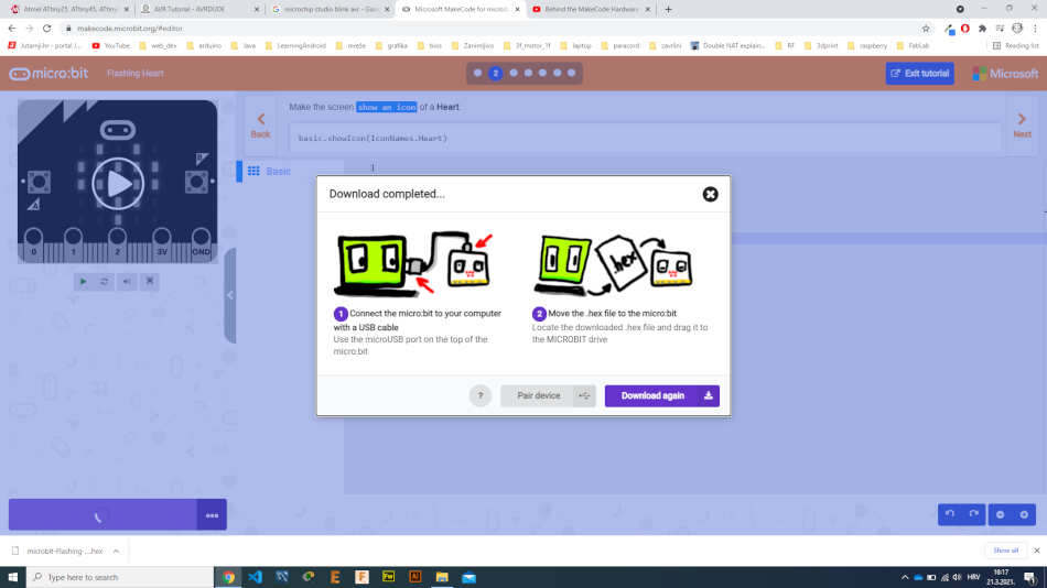
Then we copy the hex code directly to the microbit. The result can be seen in the video below.
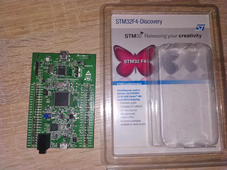
Discovery board
The STM32F4DISCOVERY Discovery kit from ST leverages the capabilities of the STM32F407 high-performance microcontrollers, to allow users to develop audio applications easily. It includes an ST-LINK / V2-A embedded debug tool, one ST-MEMS digital accelerometer, one digital microphone, one audio DAC with integrated class D speaker driver, LEDs, push-buttons, and a USB OTG Micro-AB connector.
I used Keil for programming Discovery board. Keil MDK is the complete software development environment for a wide range of Arm Cortex-M based microcontroller devices. MDK includes the uvisionVision IDE and debugger, Arm C/C ++ compiler, and essential middleware components. It supports all silicon vendors with more than 8,500 devices and is easy to learn and use. I wrote before some assembler code to rotate the leds on board.
Discovery board working