12. Output devices
This week we were working with output devices so individual assignment was to add an output device to a microcontroller board that we designed, and program it to do something. For the group assignment we had to measure the power consumption of an output device.
Individual assignment
Using commercial board
For individual assignment I chose this 5V stepper motor to test it. I planned to use it in my final project. Motor can see in a picture bellow.
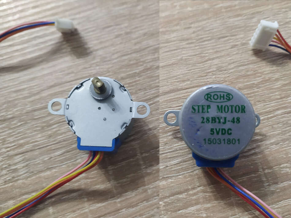
It comes with 5 wires. Next step was to found some information about stepper on web. Stepper has a marking 28BYJ-48. I used that code to find information. This site was very useful. So, this is unipolar stepper motor with following characteristics and pinouts
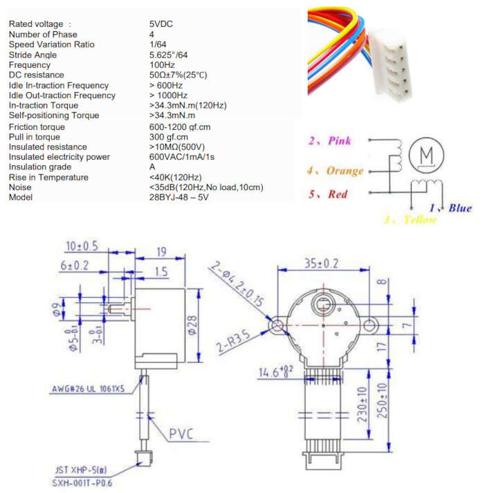
According to the data sheet, when the 28BYJ-48 motor runs in full step mode, each step corresponds to a rotation of 11.25°. That means there are 32 steps per revolution (360°/11.25° = 32). In addition, the motor has a 1/64 reduction gear set. (Actually its 1/63.68395 but for most purposes 1/64 is a good enough approximation)
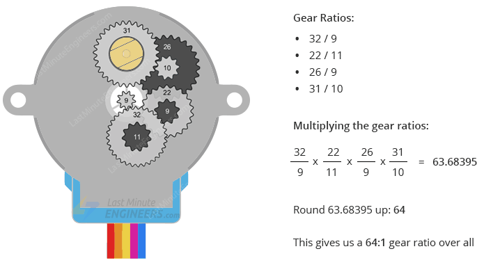
What this means is that there are actually 32*63.68395 steps per revolution = 2037.8864 ~ 2038 steps! The motor usually comes with a ULN2003 based driver board.
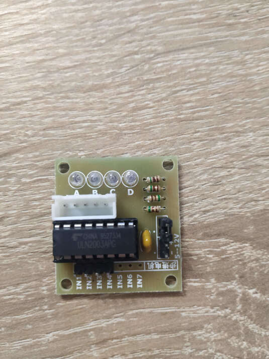
The ULN2003 is one of the most common motor driver ICs, consisting of an array of 7 Darlington transistor pairs, each pair is capable of driving loads of up to 500mA and 50V. Four out of seven pairs are used on this board. The board has a connector that mates the motor wires perfectly which makes it very easy to connect the motor to the board. There are also connections for four control inputs as well as power supply connections.
The board has four LEDs that show activity on the four control input lines (to indicate stepping state). They provide a nice visual when stepping. The board also comes with an ON/OFF jumper to isolate power to the stepper Motor. Pinout description:
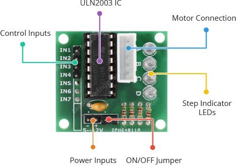
- IN1 – IN4 pins are used to drive the motor. We need to connect them to a digital output pins on the microcontroller.
- GND is a common ground pin.
- VDD pin supplies power for the motor. We need to connect it to an external 5V power supply, because the motor draws too much power.
- Motor Connector - This is where the motor plugs into. The connector is keyed, so it only goes in one way.
For connecting all the above I used my board from input devices week based on ATtiny85 microcontroller.
For connecting ATtiny85 with ULN2003 driver board I used following connection:
ATtiny85 -> ULN2003 board
- PB0 -> IN1
- PB1 -> IN2
- PB2 -> IN3
- PB3 -> IN4
I used external power supply for driving the stepper and microcontroller. It’s important to use external power supply because stepper can draw up to 500mA. If I use power from computer I need to connect GND pins together (GND from external power supply and GND of microcontroller). I used Arduino and stepper library for programming the ATtiny85 microcontroller through ISP header. I upload the following sketch for controlling the stepper motor. There was some problem with a setSpeed() parameter. First time I set those values to 500. The stepper did not turn at all. After some reading I changed to much lower value, in my case 8 rpm and then the stepper started working and turning normally.
#include <Stepper.h>
// Define number of steps per rotation:
const int stepsPerRevolution = 2048;
// Wiring:
// Pin 0 to IN1 on the ULN2003 driver
// Pin 1 to IN2 on the ULN2003 driver
// Pin 2 to IN3 on the ULN2003 driver
// Pin 3 to IN4 on the ULN2003 driver
// Create stepper object called 'myStepper', note the pin order:
Stepper myStepper = Stepper(stepsPerRevolution, 0, 2, 1, 3);
void setup() {
  // Set the speed to 8 rpm:
  myStepper.setSpeed(8);
}
void loop() {
  // Step one revolution in one direction:
  myStepper.step(stepsPerRevolution);
  delay(500);

  // Step one revolution in the other direction:
  myStepper.step(-stepsPerRevolution);
  delay(500);
}
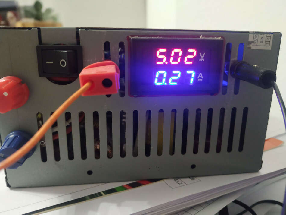
In this sketch speed was set to 8 rpm and stepper makes one full turn clockwise and then one full turn counterclockwise. When I upload the code I turn on the power supply and set the voltage to 5V. The operation of a stepper can be seen in a video bellow.
I also noticed the current drawn from external supply. It was 270mA. If we multiply current with voltage of 5.02V we get 1.35W of power.
Making and milling my own board
I wanted to design my own board with ULN2003 drivers IC included. It’s a good way to sharpen my PCB milling skills. I opened KiCAD and started designing my PCB. The main components is ATtiny85 mcu and ULN2003 stepper driver IC. I began with those two components and place din schematic editor.
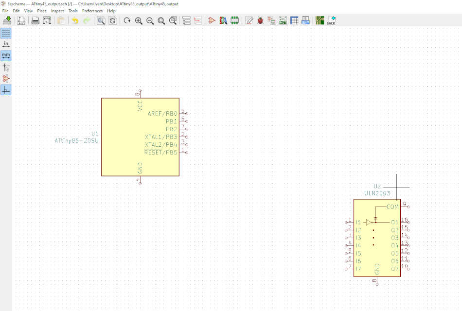
Next thing I added ISP header for programming and FTDI header for communication.
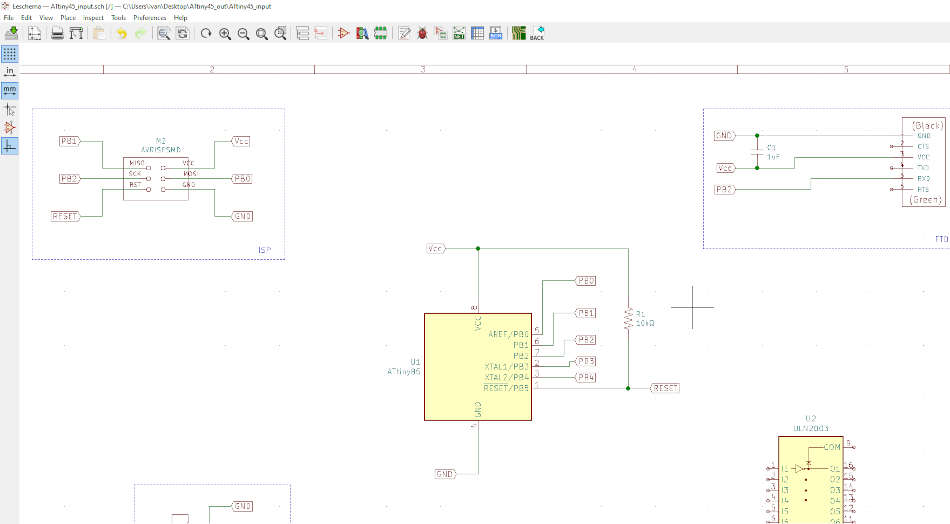
So, I added ULN2003 IC in schematic editor. The problem was later in PCB layout, there was no footprint. I added a generic 16 pin DIP package with 2.54mm pitch between pins.
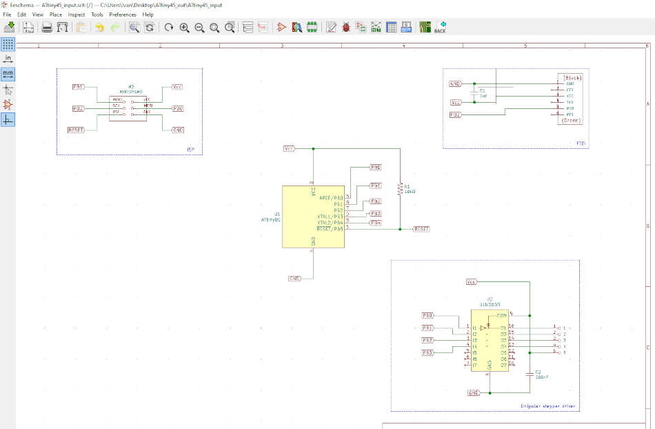
After I connected everything and placed labels I generate a netlist. Then I run the Pcbnew to open the PCB editor. Next thing is to load the netlist and placed all the components where we want.
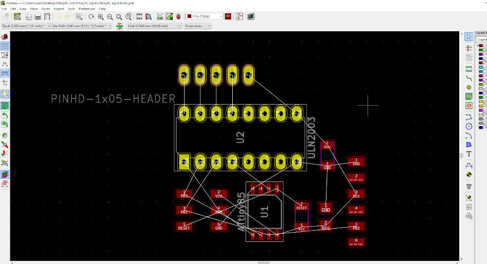
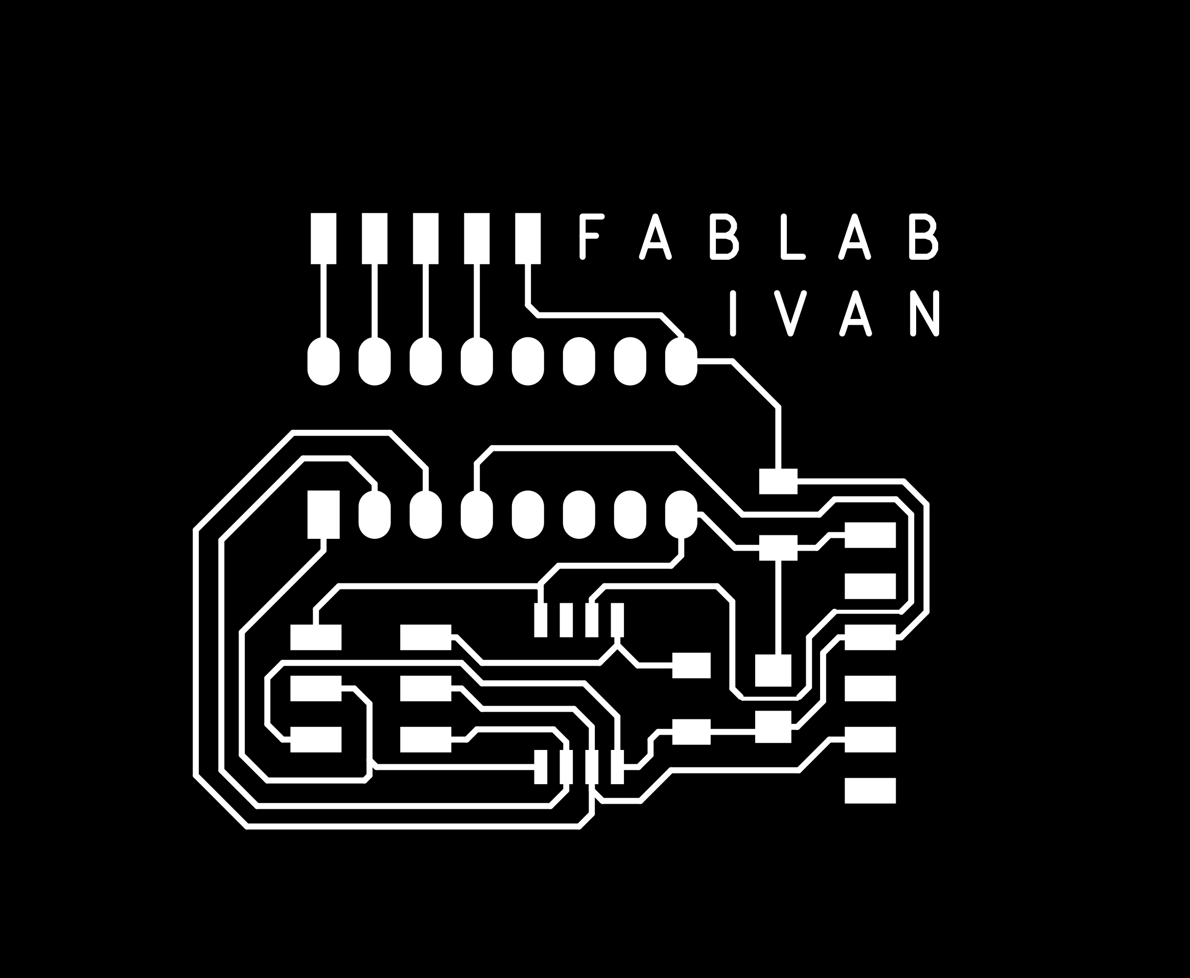
I connect all the traces. It took me a while, because I did not want to use vias. I added 100nF filter capacitor near ULN2003 IC. This is finished bord.
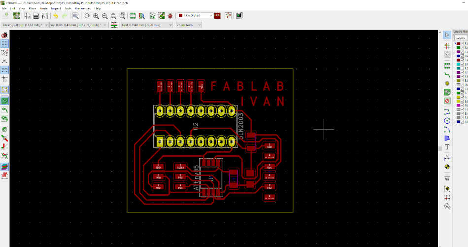
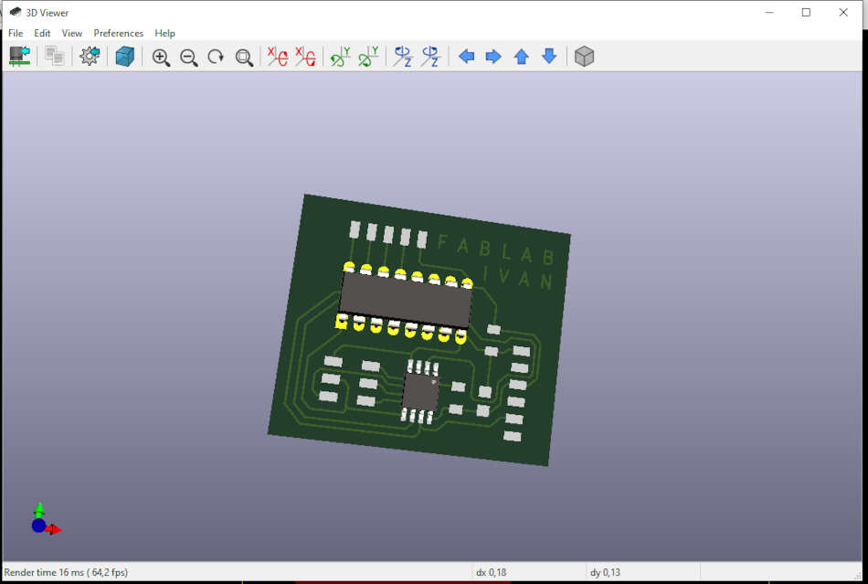
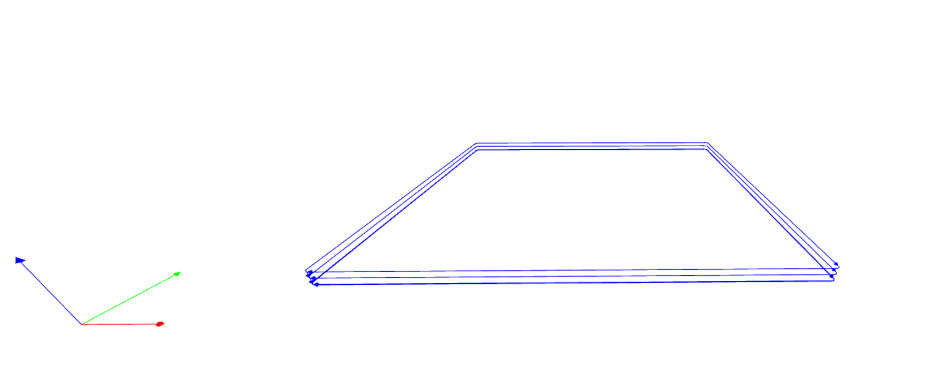
By clicking ALT+3 we can see PCB 3D model. All the traces are 0.3mm width except one line is 0.2mm.
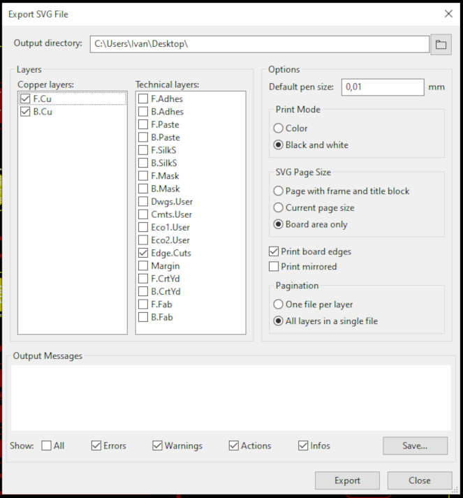
I clicked on Perform design rule check. I set minimum track width to 0.2mm, clicked RunDRC. There was no errors. In board setup I set clearance to 0.4mm. That’s the diameter of the end mill we use. Next thing is to export PCB in svg format. This is the setting I use for export.
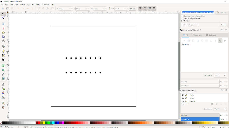
For generating png images I used Inkscape. I opened svg that I previously exported. I create 4 different layers, traces, outline, holes and background. I added all to corresponding layer. Black background is used to point out white traces and also outline layer and holes. Image needs to be at least 1000dpi, so I set that.
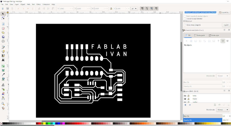
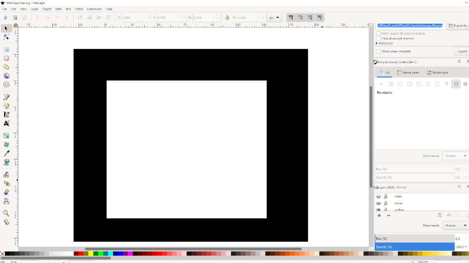
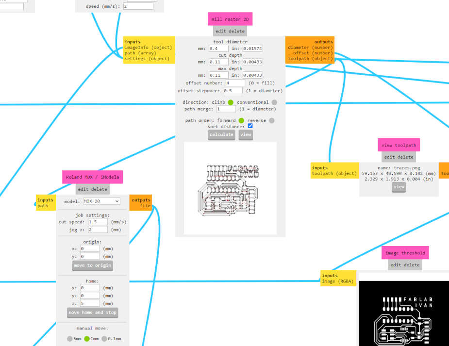
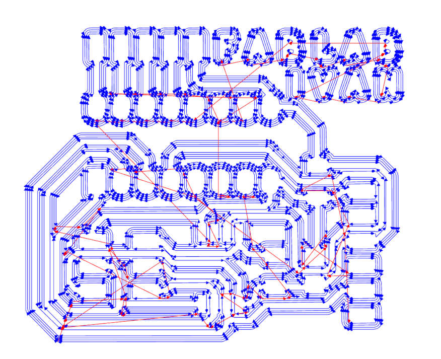
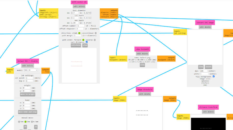
I go to File -> Export PNG and exported 3 different png’s (traces, outline, holes). Next step is to go to modsproject and selected MDX mill program. First I upload the traces png and started setting the parameters.
- Tool diameter: 0.4mm
- Cut depth: 0.11mm
- Offset: 4
- Cut speed: 1.5mm/s
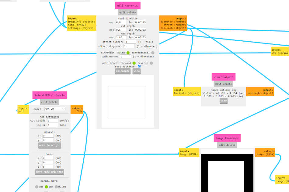
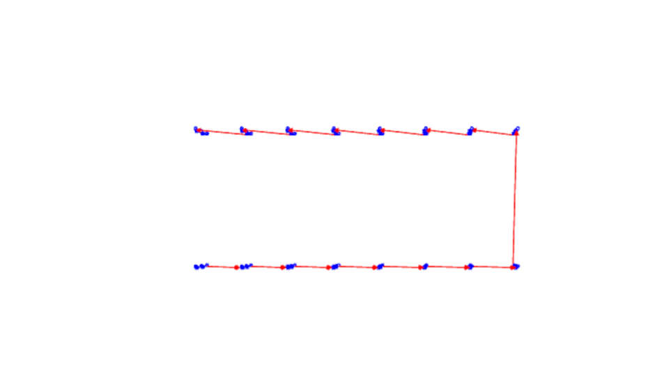
Then I open outline png in mods and set the following:
- Tool diameter: 0.8mm
- Cut depth: 0.6mm
- Max depth: 1.85mm
- Cut speed: 1mm/s
The last I needed to do is to upload holes png. I selected mill outline and the only thing I changed is tool diameter, 0.7mm.
I saved RML files using save module in mods. I used DropOut to send RML files to Roland MDX-15.
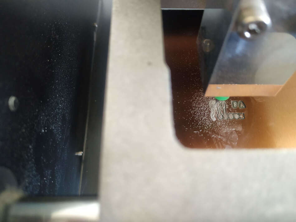
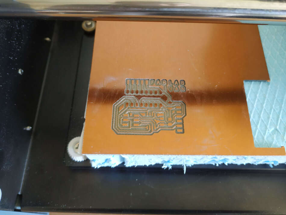
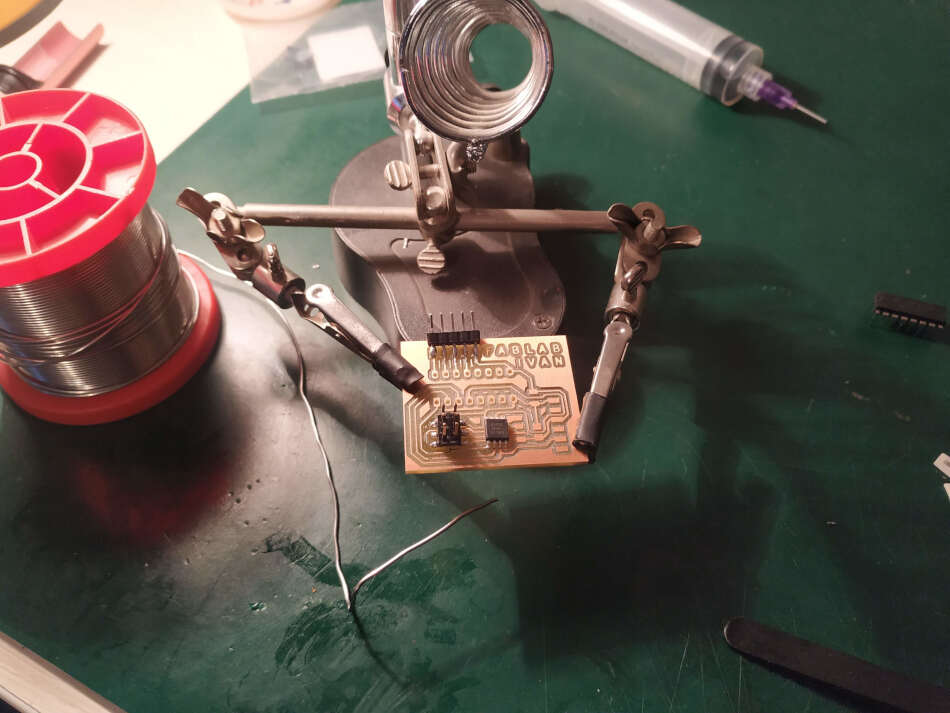
This is how the traces turned out.
This is PCB after the outline and the holes milling process.
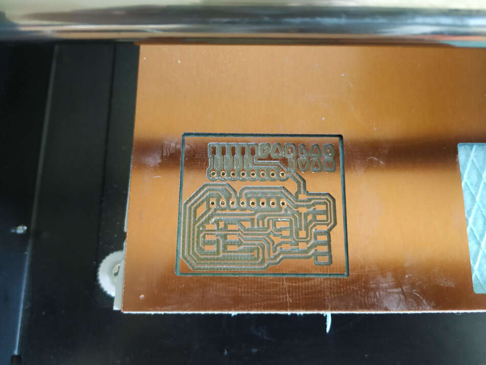
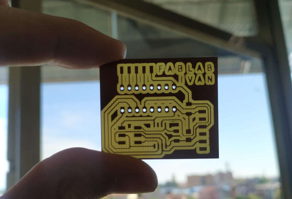
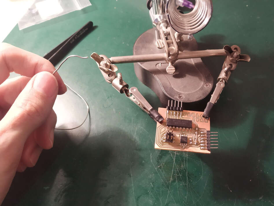
You can notice small „islands“ around some traces. This is because my end mill broke during the milling process. I swapped the end mill and started milling again on the same path. This time I wanted to save time so I set the offset traces to 3. Next step is to solder components.
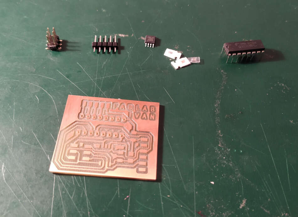
I used the following components:
- ATtiny85
- ULN2003AG
- ISP header
- FTDI header
- 10kΩ resistor
- 1uF capacitor
- 100nF capacitor
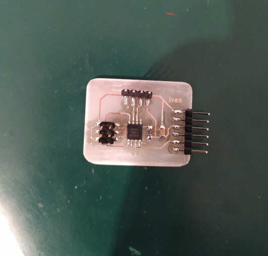
This is the finished board.
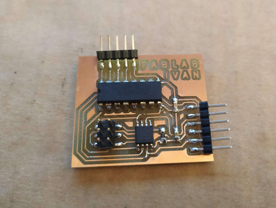
I programmed my board through ISP header with the sketch written above. After that I connected my board to 5V power supply. You can see a video bellow.
Group assignment
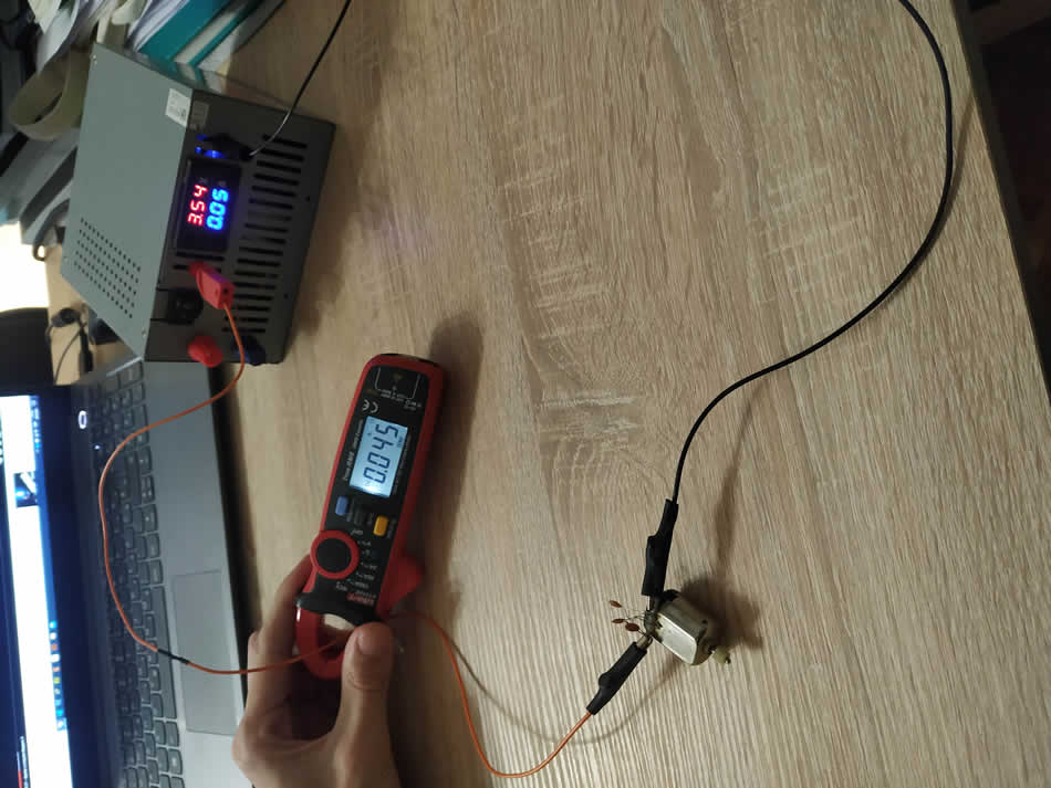
For the group assignmet we had to measure the power consumption of an output device. I used two DC motors, one with a load and another without load. You can see in a picture bellow. Left one I salvaged from a toy, the right one is from game controller. It’s used as a vibration motor.
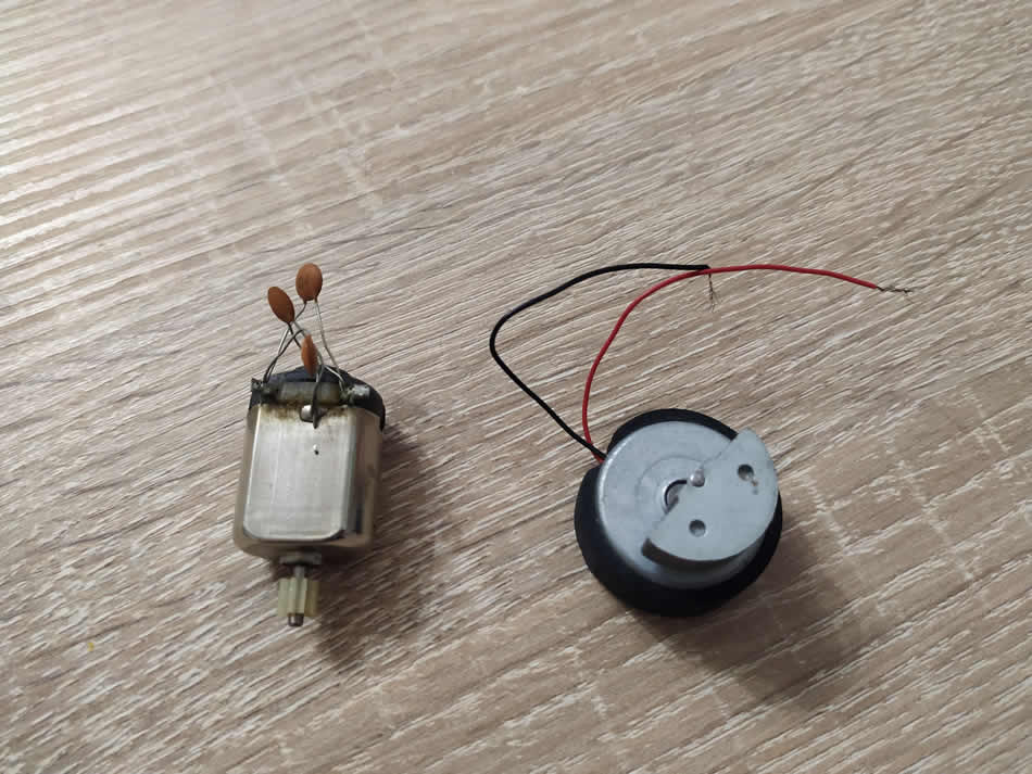
First i connect DC motor without a load to power supply and set the voltage 3.54V. To measure current I use clamp meter. Clamp meter showed 45mA. So power is voltage multiplied with current, in this case is 3.54x0.045 = 0.15W.
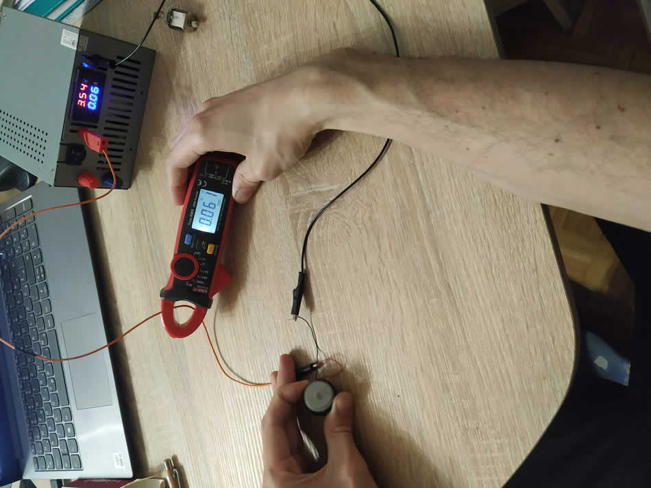
Second test that I performed is with load. I connect motor in the same way like previous. I set the same voltage, 3.54V. In this case current consumption is little higher, that is 61mA. Power is 3.54x0.061 = 0.21W.
Design files: