13. Networking
Group assignment
For this group assignment we wanted to connect 2 boards with serial connection. This only needs 2 wires between the boards. You can send data back and forth between different boards if you connect the RX and TX pin of the boards.
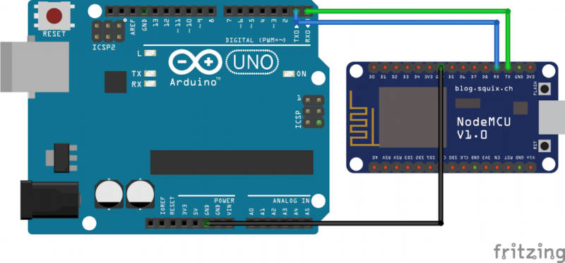
THis can be any board with TX and RX pins available. Make sure you cross connect them. The TX pin from board 1 goes to the RX pin of board 2. and vice versa.
- RX == receive
- TX == transmit sender_pic.jpg
For code we based our demo on this info found on the arduino forum. https://forum.arduino.cc/t/sending-multiple-values-between-two-arduino-serially/401278
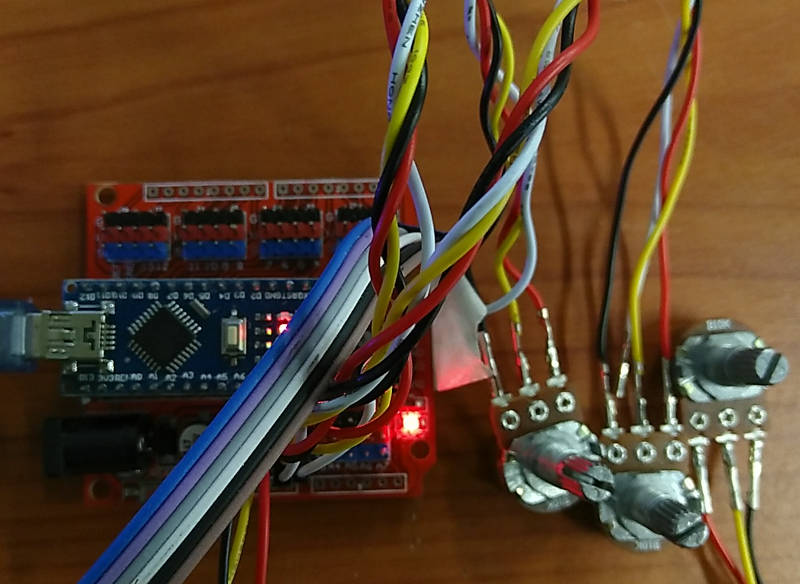
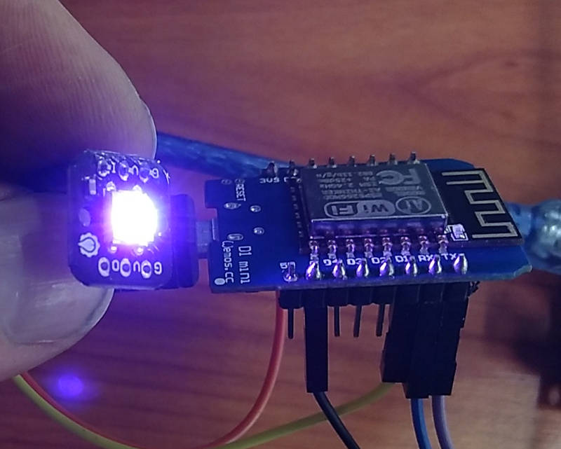
We wanted to make an RGB led controller with 3 potentionmeters on the arduino board. (this is based on the Virtualcolormixer example that comes with the arduino IDE) Data from the analogRead of the potentiometers is send via Serial to the Wemos D1 board. This board has a Neopixel and changes color based on the data received.
A screenshot of the sender code and serial output
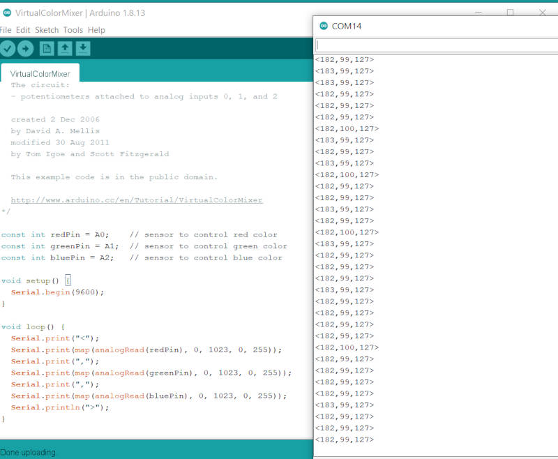
The sender code is minimal. We use a start and end character to be more consistent in decoding the receiving data later.
 Serial.print("<");
 Serial.print(map(analogRead(redPin), 0, 1023, 0, 255));
 Serial.print(",");
 Serial.print(map(analogRead(greenPin), 0, 1023, 0, 255));
 Serial.print(",");
 Serial.print(map(analogRead(bluePin), 0, 1023, 0, 255));
 Serial.println(">");
A screenshot of the receiver code and serial output
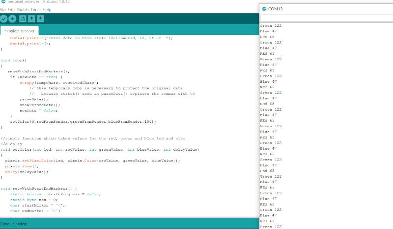
The receveiver code has some functions to parse the incoming data. And look for: ‘<’ and ‘>’
 void recvWithStartEndMarkers() {
     static boolean recvInProgress = false;
     static byte ndx = 0;
     char startMarker = '<';
     char endMarker = '>';
     char rc;

     while (Serial.available() > 0 && newData == false) {
         rc = Serial.read();

         if (recvInProgress == true) {
             if (rc != endMarker) {
                 receivedChars[ndx] = rc;
                 ndx++;
                 if (ndx >= numChars) {
                     ndx = numChars - 1;
                 }
             }
             else {
                 receivedChars[ndx] = '\0'; // terminate the string
                 recvInProgress = false;
                 ndx = 0;
                 newData = true;
             }
         }

         else if (rc == startMarker) {
             recvInProgress = true;
         }
     }
 }
The parseData funcion splits the received chars into parts based on the ‘,’ in between values.
Video of the whole thing working:
Code Files
Individual
1. Esp-Now test setup
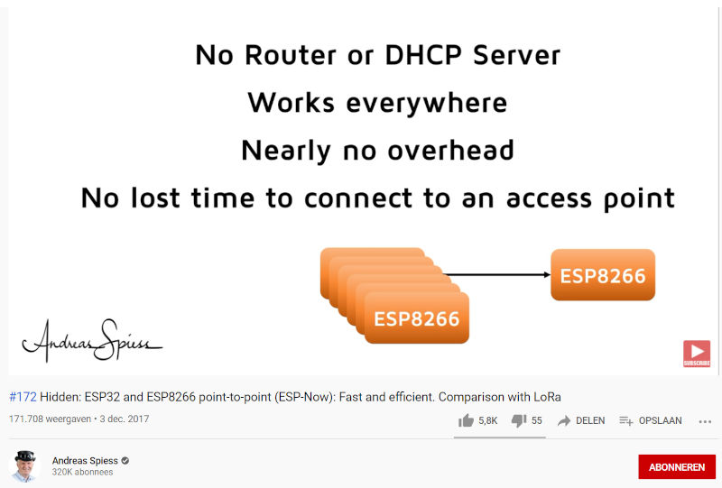
For part of the final project we need a kind of a pager system. It should be some kind of mesh networked system. It doesn’t need to be bidirectional, but that could later maybe come in handy. I found out that there is the eps-now protocol, this enables to use the wifi in the esp modules to make a mesh network. This a protocol made by Espressif, the makers of the ESP chips.
I looked up the manual on their website https://www.espressif.com/sites/default/files/documentation/esp-now_user_guide_en.pdf
I found a tutorial that explains how to make a network https://randomnerdtutorials.com/esp-now-esp32-arduino-ide/
After a few hours of trying to debug and installing/de-installing different libraries to find out why it won’t compile on the esp8266 board, i finally found this website https://www.survivingwithandroid.com/esp-now-esp32-esp8266/

In the example codes I found that the name of the include is different for the esp32 and the esp8266.
    #include <espnow.h> for the esp8266
    #include <esp_now.h> for the esp32
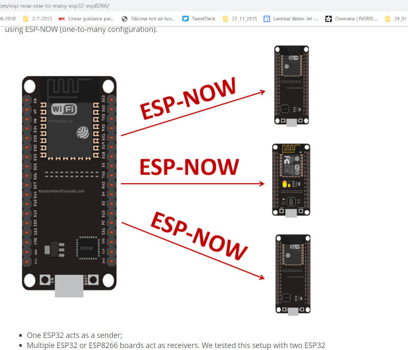
I used an esp32 board as a sender. I wanted to connect a potentiometer to send values from it to 3 esp8266 boards that act as receivers.
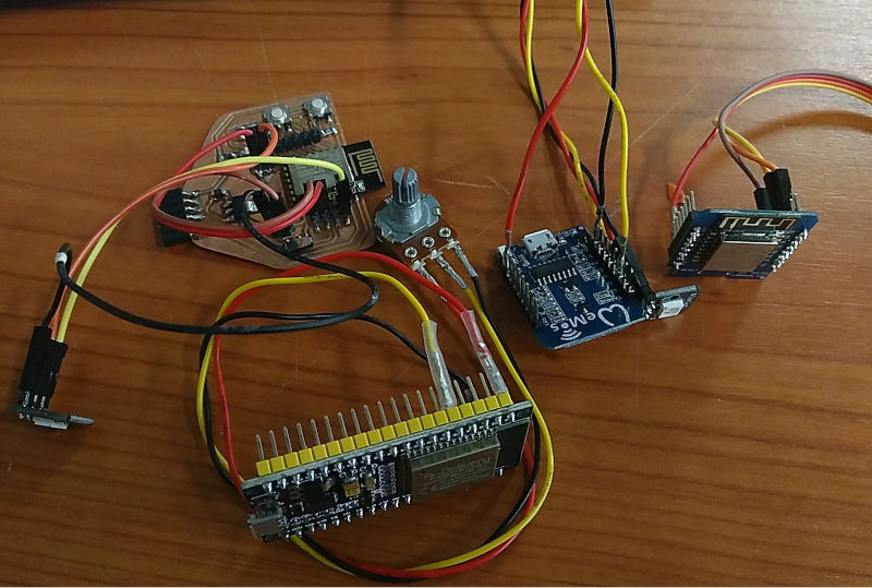
I connected a neopixel to each receiver board that I want to have change color based on the pot values send
I also found a script to read the Mac address of the esp boards, this was handy. I need all the addresses to be able to send messages to them ESP-Now uses the mac addresses to connect to the different nodes in the network.
// Complete Instructions to Get and Change ESP MAC Address: https://RandomNerdTutorials.com/get-change-esp32-esp8266-mac-address-arduino/

#ifdef ESP32
  #include <WiFi.h>
#else
  #include <ESP8266WiFi.h>
#endif

void setup(){
  Serial.begin(115200);
  Serial.println();
  Serial.print("ESP Board MAC Address:  ");
  Serial.println(WiFi.macAddress());
}

void loop(){

}
Once I had all 3 addresses I could add them to the code of my sender module 1 module doesn’t seem to work correctly, it receives the messages, but always shows red color
I also placed the sender in different rooms to test if it works longer distance. If there is not to much concrete in between it works. In our building I could go around 30m.
SENDER
in the sender code you have to create a peer node for each connected device. The peer node contains the Mac address for the corresponding receiving module.
To start I had de SENDER send random rgb values to test the receiver boards. For the first version they all get the same message send.
The sending of messages gets done by the esp_now_send command. If you use NULL as address it sends to all listed peers.
esp_now_send(NULL , (uint8_t *) &myMessage, sizeof(myMessage));
To send to individual node you can use the address of the node in de esp_now_send command. So we can send a message to each module separately. If wanted we could also send a different message to each module.
  esp_now_send(peer1.peer_addr , (uint8_t *) &myMessage, sizeof(myMessage));
  delay(500);
  esp_now_send(peer3.peer_addr , (uint8_t *) &myMessage, sizeof(myMessage));
  delay(1000);
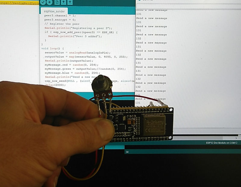
Arduino code for the esp-now sender board
/**
 * ESP-NOW: ESP32 Broadcast with ESP-Now
 *
 *
*/
#include <Arduino.h>
#include <WiFi.h>
#include <esp_now.h>
// ESP8266 Mac address (first peer)
uint8_t mac_peer1[] = {0x5C, 0xCF, 0x7F, 0x00, 0x0C, 0x51};
// ESP8266 Mac address (second peer)
uint8_t mac_peer2[] = {0x5C, 0xCF, 0x7F, 0x02, 0xF7, 0x1E};
// ESP8266 Mac address (third peer)
uint8_t mac_peer3[] = {0xEC, 0xFA, 0xBC, 0x41, 0xA9, 0x83};
esp_now_peer_info_t peer1;
esp_now_peer_info_t peer2;
esp_now_peer_info_t peer3;
int i = 0;

typedef struct message {
   int red;
   int green;
   int blue;
};
struct message myMessage;

const int analogInPin = 34;
int sensorValue = 0;        // value read from the pot
int outputValue = 0;
void setup() {
  Serial.begin(115200);
  //WiFi.mode(WIFI_STA);
   WiFi.mode(WIFI_AP_STA);

  // Get Mac Add
  Serial.print("Mac Address: ");
  Serial.print(WiFi.macAddress());
  Serial.println("ESP32 ESP-Now Broadcast");
  // Initializing the ESP-NOW
  if (esp_now_init() != 0) {
    Serial.println("Problem during ESP-NOW init");
    return;
  }
  memcpy(peer1.peer_addr, mac_peer1, 6);
  peer1.channel = 1;
  peer1.encrypt = 0;
  // Register the peer
  Serial.println("Registering a peer 1");
  if ( esp_now_add_peer(&peer1) == ESP_OK) {
    Serial.println("Peer 1 added");
  }
  memcpy(peer2.peer_addr, mac_peer2, 6);
  peer2.channel = 1;
  peer2.encrypt = 0;
  // Register the peer
  Serial.println("Registering a peer 2");
  if ( esp_now_add_peer(&peer2) == ESP_OK) {
    Serial.println("Peer 2 added");
  }
   memcpy(peer3.peer_addr, mac_peer3, 6);
  peer3.channel = 1;
  peer3.encrypt = 0;
  // Register the peer
  Serial.println("Registering a peer 3");
  if ( esp_now_add_peer(&peer3) == ESP_OK) {
    Serial.println("Peer 3 added");
  }
}

void loop() {
  sensorValue = analogRead(analogInPin);
  outputValue = map(sensorValue, 0, 4095, 0, 255);
  Serial.println(outputValue);
  myMessage.red = random(0, 254);
  myMessage.green = random(0, 254);
  myMessage.blue = outputValue;//random(0, 254);
  Serial.println("Send a new message");
  esp_now_send(peer1.peer_addr , (uint8_t *) &myMessage, sizeof(myMessage));
  delay(500);
  esp_now_send(NULL , (uint8_t *) &myMessage, sizeof(myMessage));
  delay(1000);
}
Quick overview of how this works:
- the esp_now_send command sends a message to the receiving peers. The message is build as a struct and contains 3 variables for the RGB leds typedef struct message { int red; int green; int blue; }; struct message myMessage;
- In setup we first have to register al receivers as peer with their mac address. memcpy(peer1.peer_addr, mac_peer1, 6); peer1.channel = 1; peer1.encrypt = 0; // Register the peer Serial.println(“Registering a peer 1”); if ( esp_now_add_peer(&peer1) == ESP_OK) { Serial.println(“Peer 1 added”); }
RECEIVERS
All receiver modules have the same code. So you can simultaneous have them respond on the sender message. If wanted we could vary the receiver code to behave different on receiving the message.
Arduino code for the esp-now receiver board
#include <Arduino.h>
#include <ESP8266WiFi.h>
#include <espnow.h>
#include <Adafruit_NeoPixel.h>

#define PIN 5 //=wemos D1

Adafruit_NeoPixel pixels = Adafruit_NeoPixel(1, PIN, NEO_GRB + NEO_KHZ800);

typedef struct message {
   int red;
   int green;
   int blue;
} message;
message myMessage;

void onDataReceiver(uint8_t * mac, uint8_t *incomingData, uint8_t len) {
   Serial.println("Message received.");
   // We don't use mac to verify the sender
   // Let us transform the incomingData into our message structure
  memcpy(&myMessage, incomingData, sizeof(myMessage));
  Serial.print("Red:");
  Serial.println(myMessage.red);
  Serial.print("Green:");
  Serial.println(myMessage.green);
  Serial.print("Blue:");
  Serial.println(myMessage.blue);
  setColor(0,myMessage.red,myMessage.green,myMessage.blue,100);
}
//simple function which takes values for the red, green and blue led and also
//a delay
void setColor(int led, int redValue, int greenValue, int blueValue, int delayValue)
{
  pixels.setPixelColor(led, pixels.Color(redValue, greenValue, blueValue));
  pixels.show();
  delay(delayValue);
}

void setup() {
  Serial.begin(115200);
  WiFi.disconnect();
  ESP.eraseConfig();

  // Wifi STA Mode
  WiFi.mode(WIFI_STA);
  // Get Mac Add
  Serial.print("Mac Address: ");
  Serial.print(WiFi.macAddress());
  Serial.println("\nESP-Now Receiver");

  // Initializing the ESP-NOW
  if (esp_now_init() != 0) {
    Serial.println("Problem during ESP-NOW init");
    return;
  }

  //esp_now_set_self_role(ESP_NOW_ROLE_SLAVE);
  // We can register the receiver callback function
  esp_now_register_recv_cb(onDataReceiver);
  pixels.begin();
}
void loop() {
  // put your main code here, to run repeatedly:
}
- each receiver listens for incoming messages. There is a callback function that gets called when a message arrives. Here our function reads out the rgb variables from the message and sets the color of the neopixel based on this. esp_now_register_recv_cb(onDataReceiver);
Demo video of how the system works. Both modules are connected to a serial port on the pc to also see what they do in the serial monitor.
Video of simutanous receiving peers:
Video of separately addressed peers in sequence:
This is a summary of the most useful esp-now commands:
| Function Name and Description |
|---|
| esp_now_init() Initializes ESP-NOW. You must initialize Wi-Fi before initializing ESP-NOW. |
| esp_now_add_peer() Call this function to pair a device and pass as argument the peer MAC address. |
| esp_now_send() Send data with ESP-NOW. |
| esp_now_register_send_cb() Register a callback function that is triggered upon sending data. When a message is sent, a function is called – this function returns whether the delivery was successful or not. |
| esp_now_register_rcv_cb() Register a callback function that is triggered upon receiving data. When data is received via ESP-NOW, a function is called. |
And a link to the API reference, https://demo-dijiudu.readthedocs.io/en/latest/api-reference/wifi/esp_now.html
2. Lora modules and network
The esp-now is based on the wifi signal. For our project we want to be able to have our pager communicate on as low power as possible and also have a bigger range than wifi. Lora might be the solution, it works on free radio frequencies and has longer range. We maybe would want to use these modules based on the SX1278 chip https://www.amazon.nl/gp/product/B084NWDFH1/ref=ppx_yo_dt_b_asin_title_o03_s00?ie=UTF8&psc=1
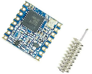
They are low power and cheap.
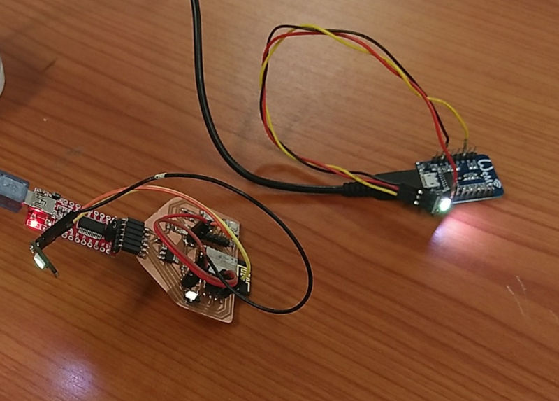
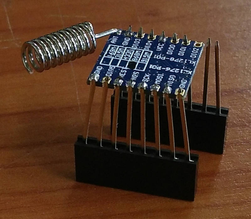
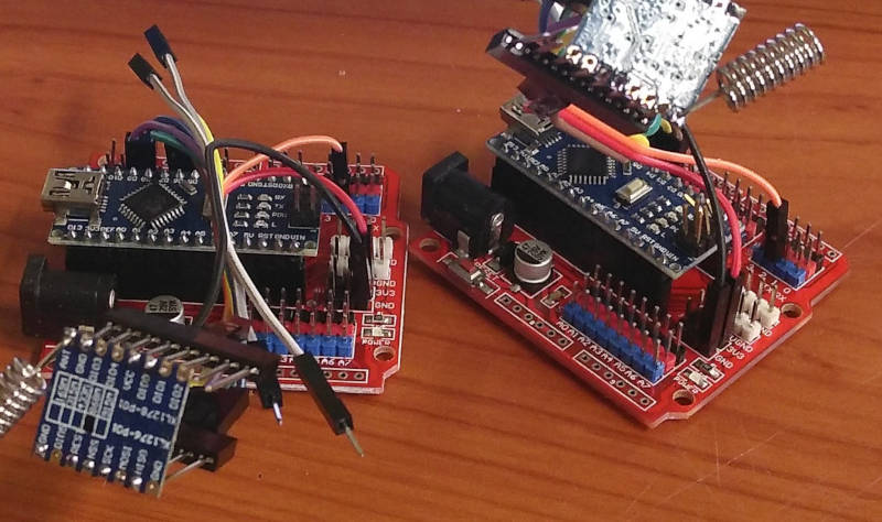
Before I make to boards to use it I want to try them out using arduino boards. At the end for the final project, we will make boards based on the ATTiny1614 and this Lora module. To connect the modules to the arduino I soldered long header pins to the module, so I could bend the pins a bit to fit the smaller distance between pins.
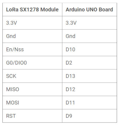
They use the SPI protocol. And i try to connect them up using this tutorial found online
https://how2electronics.com/interfacing-sx1278-lora-module-with-arduino/

I connected everything up like this.
and installed the lora library from sandeep
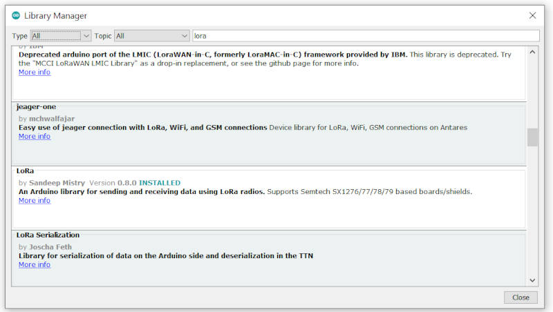
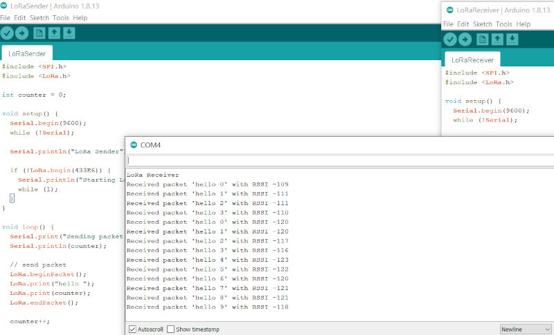
Using the simple sender and receiver example I was able to quickly get things communicating.
I had to make sure my frequency was right
LoRa.begin(866E6) instead of 915E6
Now finding a way to have each node respond individually!
3. Design board for the pager pucks in the final project to use the SX1278 lora chips.
I also wanted to prepare for the final project and include a Darlington transistor to switch the vibrating motor. I wanted to include battery connector, neopixel and buzzer. So I also had to find a kicad symbol for the transistor i’m using. Luckily the vendor RS-components provides symbols for a lot of the components, even with an installer to automatically install it in the kicad software
The LoRa SX1278 is not 5V friendly so do not supply 5V to it else the board will get damaged. Use 3.3V of Arduino to connect it to VCC pin. Connect all the GND pins to GND.
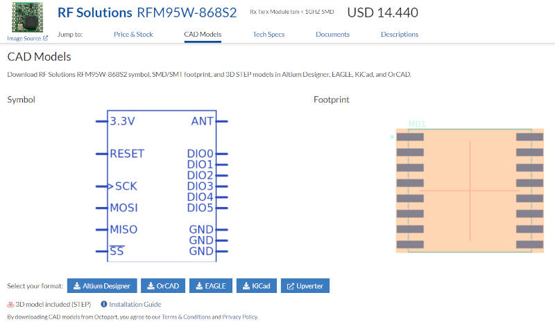
First thing was that I did not immediately found a symbol and footprint for this little board. Also dimensions are not compatible with 2.54 spacing of pins. So I thought of making a board with header pins to connect it to. But that would only be temporary. After some further searching on the internet i came across this RFM95 module, which seems to be the same formfactor as my SX1278 modules.
I found a link to footprint for pcb on octopart:
https://octopart.com/rfm95w-868s2-rf+solutions-52732389#PriceAndStock
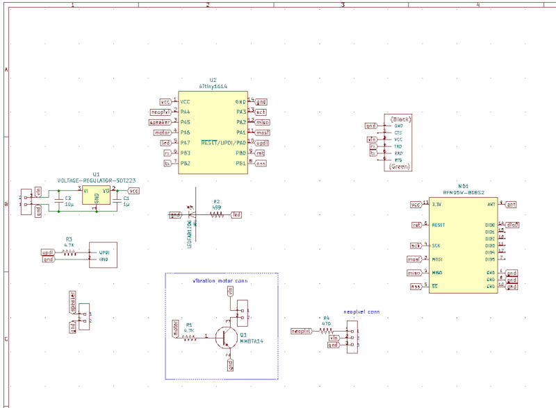
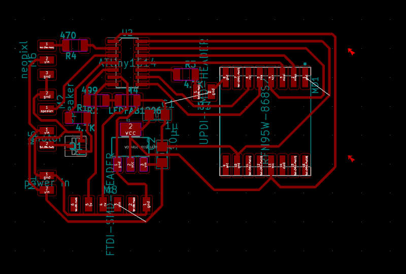
this is the design i made in Kicad:
Programming the boards These board use the UPDI method. I don’t know that. But i found a website explaining how to use arduino IDE with these boards
https://www.electronics-lab.com/project/using-new-attiny-processors-arduino-ide-attiny412-attiny1614-attiny3216-attiny1616-attiny3217/
I had to install more ATtiny processors in the board manager. Using this file http://drazzy.com/package_drazzy.com_index.json to install the megaTinyCore by Spence Conde
I used an arduino Nano and made it into the jtag2updi programmer. I already had put a 4.7k resistor on the updi pin and provided a header on the board to be able to program it.
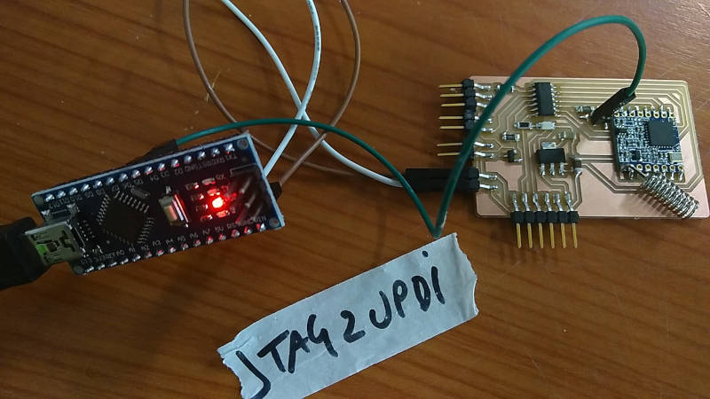
According to the datasheet at 3.3V the 1614 chip can not run faster then 8MHZ internal clock. So lets try that. I tested the programmer and board by putting a blink script in it. That worked! Moving forward!
The Lora library uses some defined pins for arduino connection. I had to put in custom pins for that.
#define ss 6
#define rst 7
#define dio0 8
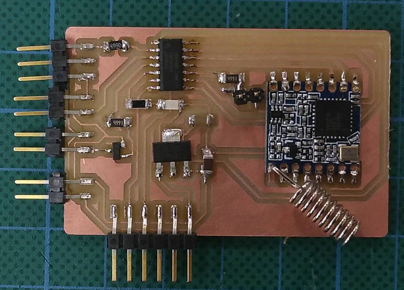
Update!!!! Bugs found:
- 5V from ftdi not connected
- dio0 pin from Lora chip not connected
But I adjusted the receiver code from earlier and got it work on this board.
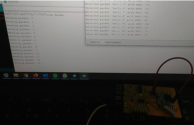
In the near future I will try to add the timer, motor and neopixel to fully test the pager puck.
Files
- espNow_findslaves code
- espNow_pixel_receiver code
- espNow_sender code
- LoRaReceiver1614 code
- LoRaSender code
- tiny1614_lora.sch schematic
- tiny412_lora.kicad_pcb pcb