4. Electronics production
Assignment
The assignment for this week was to mill and solder a PCB board and a programmer that would blink a light. During this week I was able to familiarize myself with the process that the CNC machines use to mill boards as well as which bits to use. Following the lecture I learend all about the different properties of the CNC including how the bit bites as well as methods of soldering PCB boards and CAM softwares to use to mill our boards. This lecture greatly prepared me for the assignment at hand as I had never before used a CNC. Note I was extremly constrained during this weeks assignemnt. Due to my quarintine I was unnable to accquire components that I needed to solder boards. I had to wait to recive new components from our labs. I have linked a workflow that I created for using mods and milling using candle below A resource that helped me alot during this week was a Sheek Geek.This contained information about how to use Eagle as well as how the schematic worked and why each component was necessary on the board. I referenced this numerous times when soldering as well as during a later week when I created my own blink board.
File Downloads
Links
Group Assignment
The group assignment for this week was to characterize the production rules for our lab’s PCB production process. I had previously been in direct contact with COVID so I had to quarantine and was out of the lab for the entire week. I aided my group in the group assignment by creating a doc and defining the various terms for our process including Plunge rate, Material depth, and various speeds within the machine. My classmates who are in the lab will test different settings of these on the mills themselves and further define these terms. Group site found here.
Milling Programmer
For my personal CNC mill I have downloaded a CAM called Candle which dose work with my personal CNC. This software was directly downloaded form the internet and allowed me to connect to my CNC by the port on my laptop and control the axes of the machine as well as import and mill files. In order to import Eeagle files to this software I would have to use mods and convert the file so it could be cut on my CNC. I followed the workflow in the tutorials of Fab Academy with the programmer and was able to complete the workflow. The process includes important a PNG and creating the program. The mod created a Gcode .nc file that I would import onto my personal CNC to mill
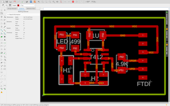
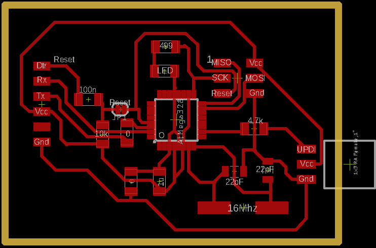 This is the original Eagle file that would be imported into mods, converted, then finally imported into candle to be milled.
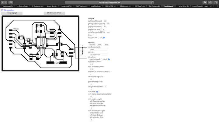
This is the photo of the completed toolpath of the Programmer I would go on to mill and solder using my personal materials. I followed the complete workflow for the Gcode exportation on a 2D PCB mill and was left with a .nc Gcode file. I had to import a PNG image of the schematic and select an outoput (.nc file). From this point I imported the file into candle, the software that will cut PCB on my personal mill. Candle then generated a milling path on which it would create my pcb. I used mods to create this PCB as shown in the photo. In order to export the photo as a PNG, I have to export as an image from Eagle then set it to monochrome, Finally I selected a DPI. I then inverted the Image in Candle and sent the File to be milled.
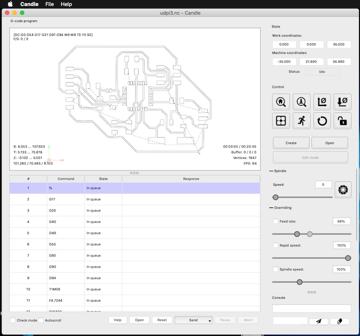
Above is the tool path for the programmer set and homed ready to be milled on my personal CNC. I will solder this board in order to complete this weeks assignment. I used a .005 engraving bit in order to engrave the baord and a 1/32 end mill bit to cut the board out.
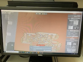
This image shows the screen on which I completed the setup procedure to mill my programmer. Different from above, I am now using my school’s Bantam tools CNC which has a differnt set up process. To start I imported the file and positioned it in the corner of the PCB material on the software. Then I tabed down a peice of PCB and slid the conductivity clip overtop of it. I then inserted a bit, in this instance the 1/32 end mill bit. I had to select the tool in the menu on the top right and then locate the tool. This process touched the bed of the CNC with the bit to figure the width of the PCB. Then I had to use the bit breaker program to figure the engrave depth. This machine automaticly lowers the spindle unlike my SainSmart CNC. Once the bit touched the PCB, it had discovered the engrave depth allowing me to accept the value for the width of the board. Finally, as the CNC had alrady been zero’d, I homed the axes to where I wanted it to mill. I then selected in the bottom right engrave and the right bit and pressed continue and the CNC began milling.
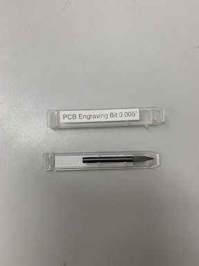
Above is ana image of just one fo the bits used in the milling process of the PCB. The bit pictured is a .005 engraving bit that I used to mill the traces of the board itself. The other bit I used was a 1/32 end mill bit that was used to make the traces wider as well as cutting the outline of the board.
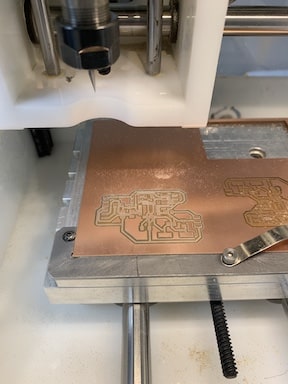
This image shows the PCB after the pads and traces have been milled. By this point in the process, both the 1/32 end mill bit and .005 engraving bit have made a pass over the board. The next step will be to switch back to the 1/32 end mill bit to mill the outline.
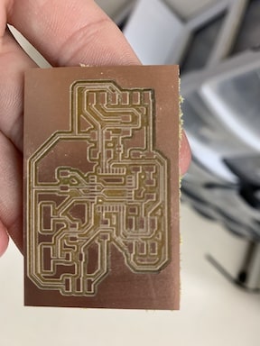
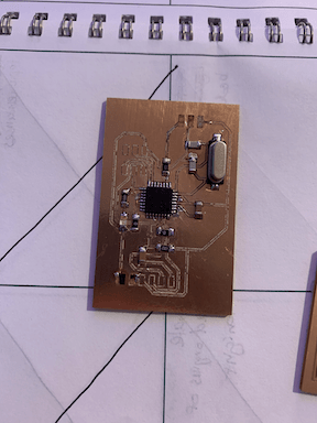
Above is the finished PCB of the programmer as I had finished running the engrave and the outline of it on my school’s CNC machine. Following taking it off I vaccumed the excess dust from the milling process as well as washed the board with soap and water. I will now solder this board with the surface mounted components.
Soldering Programmer
In order to properly solder the prorogrammer I first had to pull up the schematic diagram which showed me where all the components went by identifying them based off their given value. I was given a sheet of paper with all the components grouped which greatly simplified this process. In order to not confuse parts first I would apply a bit of flux to the pad then apply a small ammount of solder. Then I would select a certain component from the paper with tweezers and hold it on the solder while heating the pad with the iron. Finally I added solder to the other side to complete that component. I repeated this process with all components. When it came time to solder the LED I had to use a multimeter to first check the polarity. I used the diode function to determine the positive and negative terminals. In order to solder the chip I lined up the corners and taped it down. Then I soldered the corners so that I could line up the pins. To solder neatly I used flux and created a bridge then removed the bridge leaving all the pins soldered.
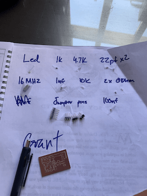
This image shows the sheet with all the components needed for the programmer organized so that I am able to quickly solder them in place without having to use the multi meeter each time to check the value of each capacitor and resistor
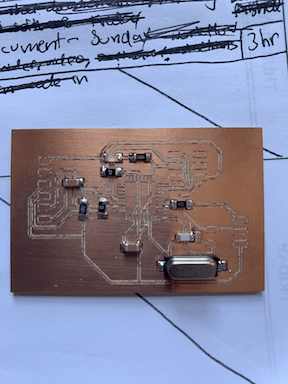
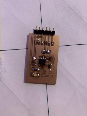
This is the board with everything soldered on except the chip itself. Due to my COVID restriction I had to pick up parts from school and the chip was forgotten, to maximize productivity I soldered the rest of my components and come next lab time I will pick up the chip to complete the programmer and to test its functionality.
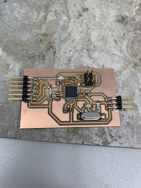
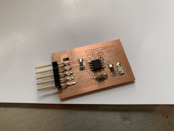
Above is the completed programmer. I have soldered all the parts including the core by using a flux pen and the drag method, the headers, and the resistors. I will upload the program to this baord to be able to use it as a stand alone programmer. This board was milled with no solder mask making it more difficult requiring more precise solder.
Above is a time lapse of my programmer being engraved. As you can see the bit is following the traces made in eagle and then imported into the program. At one point in the video you can see teh software showing the bit as it mills out the board. This left me with all the traces completed and only the outline remaining.
Programming the Programmer
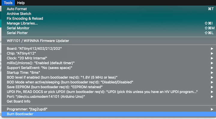
To start the process of programming my programmer, I first connected my programmer to and ISP board. Then I ran a simple program that blinked the LED on the board to confirm that everything was functioning correctly. Once I confiremd the LED was blinking I began burning the Arduino bootloader to my programmer which compiled and allowed me to program other boards like a blink board from it. This gave my PCB board the ability to function as an Arduino. Once the bootloader was burned, I connected the blink board via the headers to test that I could not only recive code on my programmer but send it as well. I used the same code that I used to test that the programmer worked and uploaded it to the blink board using the upload using programmer option. I had to set the com port, the chip, and the jtag2updi programmer that I used with the blink board as I was programming it indirectly. Once the code had been uploaded I confirmed that both worked by changing the button to where it would remain on for 200 milliseconds and turn off for 1000 milliseconds.
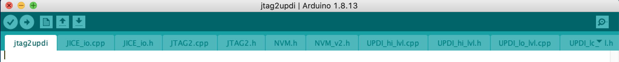
Above is an image of Jtag2updi. This is a folder that I had to download in order to be able to use my arduino as a programmer and upload code to my processor on the baord I created. When downloading the file I had to make sure it had the files in one file with the arduino code in order to have correct files to upload to the arduino.
Once I had installed the Jtag2updi file from GitHub, I had to unzip the file in order to access the code. For the installation of UPDI I ran into an error where the files needed were in the wrong location so in order to correct this I had to relocate the files needed into a file containing only the Arduino Jtag file. Following Dr Harris’s sheet geek found here I had to rename the folder from Jtag2updi-master to Jtag2updi to have the correct files to code my arduino. This was correct because when I opened the file in arduino, multiple tabs appeared. Finally once I had the file completed I was able to upload it to my arduino.
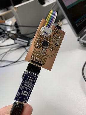
This image represents me connecting the programmer to an ISP to burn the bootloader. This was the first time I hooked it up it worked first time accepting the bootloader. I could now hood the blink up to the programmer and upload code directly.
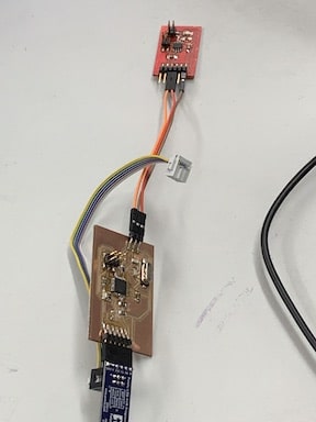
This image shows me connecting the blink board to the programmer to complete the final test that my programmer could send and recive code properly. I hooked it up via the headers on my programmer and uploaded code from arduino. It worked and let me blink the board from the programmer.
To conclude the programmer I cut the trace that allowed programs ot be uploaded so that no new programs could be run on the board istself other then the bootloader so that I could now use my programmer to program other boards.
Working programmer and blink
This video shows both of my boards connected and working. The programmer is running the Arduino bootloader and is sending the code that is making the LED on the blink board blink.
Milling Blink Board
I downloaded a Software Candle and imported the .nc file I created in mods. Once importing the design I now would be able to mill the board. I imported the schematic from Git to Eagle CAD. Then I exported a PNG of the schematic in monochrome so that I could use mods to accquire the desired tool path. Once I had the file in candle I began milling the baord using the same bit as mentioned above for the programmer.
Above is the initial Eagle schematic showing the blink board. This file was exported into the Bantam CAM software to be cut into the PCB board. Each of the spaces in the board represents a pad of copper on which a surface mount component would be soldered such as the chip which in this case was a AT412 chip or the resistors.
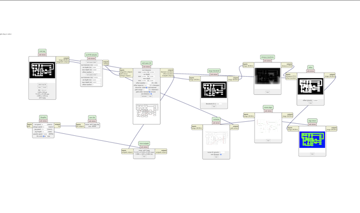
Above is an image of the Blink baord being transformed through mods. I imported the eagle schematic as a monochrome .PNG file. Then I set the output as a .nc file. This file will be transfered over to candle to be cut and soldered to create the blinker board using the AT412 blink board.
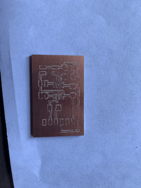
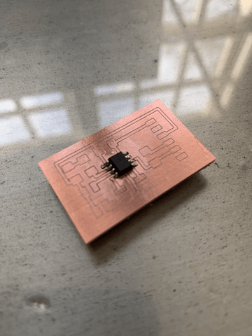
Above is the finished product the milled out Blink board. As you can see the mill has etched away the copper top surface allowing for currents to flow to certain components as they will be attached to conductive pads. In order to solder this I will use the stuffing method and solder the inside components first then moving to the outside of the board.
Soldering Blink Board
To begin my soldering process of the blink board I soldered the AT412 chip. I started by tacking down each coerner to prevent movement. I then used flux and went along each side of the core soldering each pin carefully to prevent the formation of bridges. When bridges where formed I used the solder sucker whihc quickly reverted the joints back to their pads due to the flux
As see above is the AT412 core completley soldered to the blink board using the techniques mentioned above. After this I began to solder the rest of the surface mount components that would allow me to program the board.
After soldering the rest of the components I concluded the blink board by using the flux pen to clean up my board overall. I then inspected for any joints and found none. I did however while soldering the headers remove one pad on accident which was not going to be used anyways. After finishing the soldering I programmed the blink board.
Testing blink Board
To start off which programming the blink board I began by hooking up my arduino uno to my laptop and uploading arduino ISP to it. This would alow for me to use the arduino to upload programs to my blink board. I then downloaded a zip file called jtag2udpi. This file allowed me to upload programs to my core through that programmer. I was then able to select my core, progeammer, port, and board to uplaod the blink program.
Below is a video of my blink baord functioning running the basic arduino code. This is demonstrating that all of my components work together properly. I have the blink connected to the arduino uno programmer which allows for the uplaod of code in this case the blinking LED function on my board.
I did not use the programmer I created while testing my blink board due to the fact that I had not completed it in the order of programmer first and had fallen behind. I was out under covid protocols for this week and once I finished the blink board, I squared away my documentation with it first.
Failures
While downloading software to mill my board I ran into lots of difficulties due to the lack of compatibility while using a Mac. I tried to download 2 different softwares both with no success. The first software I attempted to install was FlatCam as It was mentioned in the lecture. I attempted to install it by using the terminal function on my laptop but each attempt I was left with an error message reading that there was a newer version of the software available when in fact I was using the newer version. The second software I attempted was CNC.js as one of my classmates had used the software before in the past. I attempted to download the zip file from Git but it would never unzip and it would keep failing to be downloaded.
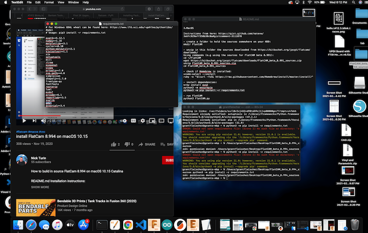
Above is the error message I was receiving while attempting to install Flat Cam through the terminal of my laptop. I attempted to troubleshoot this by downloading different versions of the software but it was to no success.
Over the course of this assignment I encountered numerous errors. While downloading the CAM softwares I realized that some were not optimized for MAC after attempting to install them through the terminal for considerable periods of time. Soldering was where I encountered the most errors. While soldering the Blink Board I ran into my first problem by using a solder sucker and ripping off one of the pads causing me to have to ditch that board and begin the process to acquire another board from the lab due to my quarantine. I encountered this same problem on the programmer itself as well causing me to have to restart. I had removed the soldering iron from the board after heating a pad and it fell right off. Both of these errors taught me to increase my patience as well as my precision so that no more unnecessary errors were encountered.
Above are two images depicting my failures in both images the dark black pad represents the pad that was ripped off. I tried many techniques to salvage the board including using jumper wires but I had no success getting it to connect properly.