8. Embedded programming
Task
For this week’s assignment I had to use as many programming types to blink the AT412 board from week six using a button. I decided I will use Arduino, Block code, and Port register. These are all different variations of C. This week I learned how to program. I was very unfamiliar with programming before going into this week but after practicing and learning through videos, I learned how to code a AT412 chip using a port registry as well as an Arduino adding inputs and outputs to the code. I learned through this as well how to use the pinout for the chip to identify which pins needed to be initialized.
Arduino Programming
Prior to this week’s assignment, I had already used Arduino to program my blink board to light up an LED at the press of a button. This was a good learning point for me so I chose to include it in this week as well. I had to set the correct pins as input and output in the code to make sure it world correctly. I figured this out by referencing the schematic and pinout for the AT412 chip frequently. Once I had the blink board connected to a programmer I compiled the code to ensure it would upload using a programer. Within the Arduino, I had to choose the chip I was using which was an AT412 and then use the JTAG2UPDI to be able to program using the programmer. Finally once the code had finished uploading, I was able to press a button and the LED would light up.
Code Example
void setup() {
  pinMode(0, OUTPUT);
  pinMode(1, INPUT);
}
void loop() {
  if (digitalRead (1) == 1){
  digitalWrite(0, HIGH);   // turn the LED on (HIGH is the voltage level)
  delay(1000);                       // wait for a second
  digitalWrite(0, LOW);    // turn the LED off by making the voltage LOW
  delay(1000);    // wait for a second
}
else {
  digitalWrite (0, LOW);
}
}
Below is a video of the blink board functioning with the basic arduino code uploaded to it. The code used is a variation of C that uses Digital read instead of having to manually register the pins. Arduino is more user friendly than port register and simplifies the code, but for this week’s assignment I will be using both. Each software I will use is a variation of the language “C.”
Block Code
Another software I used was a web based software similar to scratch and utilized blocks that functioned as DigitalRead/Write. The software is called
BlockyDuino and is a block based version of the Arduino software. Similar to my arduino code I used DigitalRead and Write blocks and identified my input and output pins in the blocks which would allow it to light the LED. I could then change the delay at which the LED blinked within the software. Once I was finished creating the block code I converted it over to text and was able to compile and upload it to my blink board using Arduino IDE.
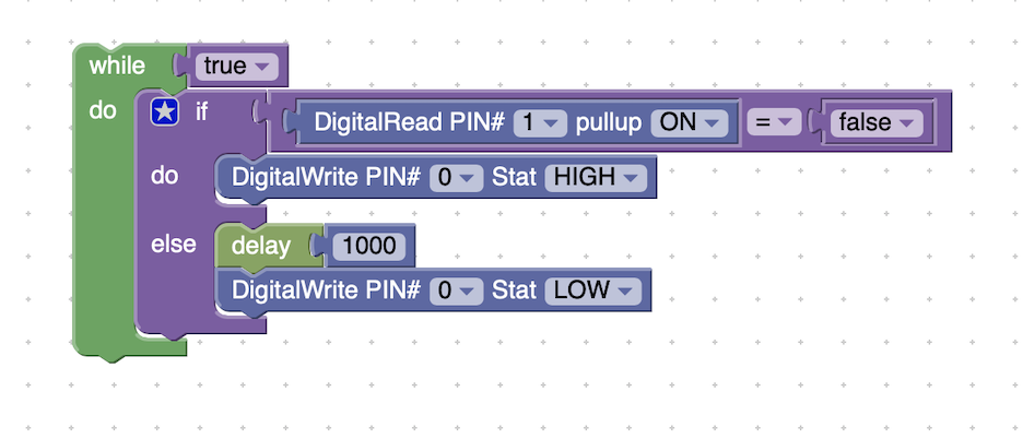
Above is an image of the blocks put together in a way that lit up the LED on my ATiny412 board I created. It reads that my button is pin 1 as an input and then initializes the pull up resistor inside. Then the code uses an if else loop to where if the button is not pressed the button lights up using the digital read block and if the button is pressed then the code turns off the LED. This is all done through using the digital read block and setting the LED pin to either HIGH or LOW for on and off. This code was much simpler when compared to the bare metal programming using port registry and I learned alot about what each portion dose in the code by the blocks having been inexperienced in the realm of coding beforehand.
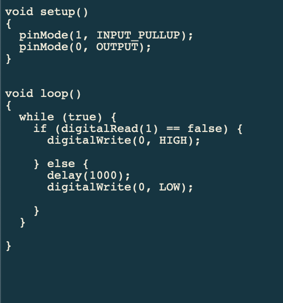
Above is the block code translated into a written program that I imported into Arduino to upload to my board. I first had to copy it over. Then I tested by compiling the code to make sure there were no problems which I already knew but was just double checking. I then ensured that I still had JTAG2UPDI uploaded to the Arduino Uno I was using as a programmer. I then selected the port chip and board in arduino and uploaded using a programmer. Finally once the code was done uploading the button lit up.
Port Register
Before starting to program using port registry, I first learned about what it was by a series of videos provided to me by my instructor. These vidoes ran through the basics such as using binary to identify each pin being used in the code and how to set it to an input or output. These videos are mentioned throughout to reference the datasheet throughout the coding so that is where I started. I used the ATiny412 datasheet to figure out what the pinout of the chip was so that I could begin to write the code.
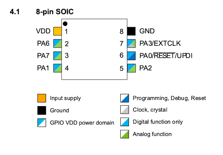
Below is an image of the pinout for the AT412 chip since I was using pin 1 for the LED and pin 0 for the button I referenced the same pins on the chip in my code. PA0 and PA1 according to the pinout where the corresponding pins that I would identify in my code.
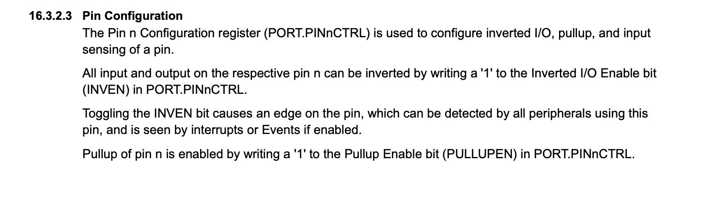
Above is another image I collected from the Data sheet. It showed me how to use PORT.PINnCTRL. This pin is used to initialize the pullup resistor inside the button and to configure the button itself. I at first tried to use the PORT.DIR for the button thinking it would work but this returned multiple compiling errors. Once I fixed this I was able to upload my code and finally after numerous attempts the code worked.
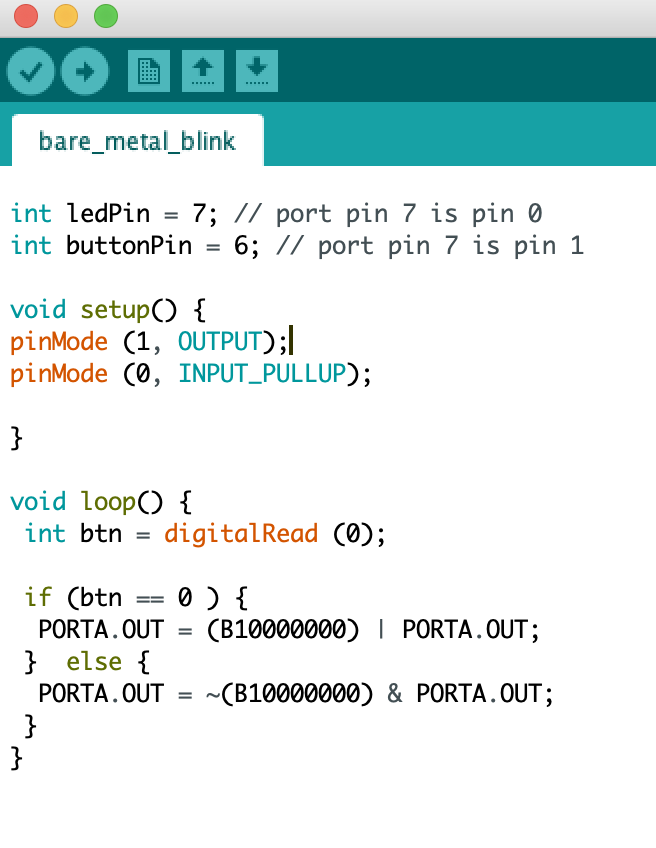
In order to use the port registry to program my ATiny412 board I first had to figure out which pins were my input (button) and output (led). Once this was setup it was time to begin the void setup. First I had to use the commands PORTA.DIR and use the binary for the LED which was 10000000 and then use PORTA.PIN6CTRL which configures the button pin and the pull up resistor at the bit value of 00001000. Once I had my input and output pins configured I was able to begin writing code in the Void loop. In the setup the first thing I had to do was initialize the button and then shift it left because each bit recognizes a corresponding pin and in order to write the correct pin it had to be shifted. The last segment in the code is using the button to turn the led on or off. I code that if the button value is equal to zero (off) then the LED will be off but else the button is pressed returning a value of 1 (on) then the LED will turn on. I completed this weeks assignment by using bare metal programming, block code, and arduino to program my blink board.
int ledPin = 7; // port pin 7 is pin 0
int buttonPin = 6; // port pin 7 is pin 1

void setup() {
PORTA.DIR = B10000000;
PORTA.PIN6CTRL = B00001000 | PORTA.PIN6CTRL;

}

void loop() {
 int btn = ( (1<<6) & ~(PORTA.IN)) >> 6;

 if (btn == 0 ) {
  PORTA.OUT = (B10000000) | PORTA.OUT;
 }  else {
  PORTA.OUT = ~(B10000000) & PORTA.OUT;
 }
}
Above is the final code that worked using the button to blink the LED on my ATiny412 board. I used bare metal programming and bits ot identify pins ot create this program.
Above is the a video of the code running on the blink board and the LED lighting up based off the press of the button.
Troubleshooting
I ran into numerous problems with coding using port registry. In order to troubleshoot these problems I individually set each pin that I initialized using bits to digital read and once I found the one that made it stop working I looked through the data sheet and corrected my problem. Instead of using PORTA.PIN6CTRL to configure the button I was using PORTA.OUT. Another error I encountered was not shifting the bit over. This was causing me to write to a pin where nothing was occurring. Once I fixed all of these errors I wrote in the correct code and uploaded to my blink board and it worked successfully as intended through the code I wrote
Above is an image of the digital write replacing the bit identification. I used this process to figure out the error line in my code then correct it. This identifies the code using the arduino program and then as I set it to input or output does what it is intended. Once corrected I compiled and had a finished code.
Link to group website found here.