9. Mechanical Design
The assignment for this week is to create a machine that includes mechanism, actuation, and automation as well as to build the mechanical parts and operate it manually. Since our class is so large we divided into two groups and brainstormed two different machines to create. All my classmates work can be found on our group website found here.
Intro Video
Below is a brief video introduction of our machine as well as some of the basic functionality. Video voice over by Graham Smith and filming by me
Ideas
For the creation of our machine for this week we wanted to create an automated pizza preparing machine. In order to do this we first started out by brainstorming some rough ideas about how we would assemble the machine. It was decided that we would create a bed that had rods going either way allowing the pizza to be moved anywhere along the bed. We would then use a raised axis that could be moved similarly. Our group decided we wanted the interface to be that similar of a 3D printer so we used the digital interface Marlin. Marlin allowed us to code the machine as well as add tool swaps so we could swap between extruding sauce and cheese onto the pizza. We are going to create the machine frame in CAD. A video that helped us visualize what we wanted to create can be found here.
Sketch
Below is an image I sketched of a first iteration of the pizza producing machine that my group is trying to create. This image is modeled after an Ender 3 with an X and Y axis on the base and a X axis across for the extruders. The bed would be on dowels allowing it to move around and the xtruder would have tool swaps allowing for switching between meat and cheese. This was only a first variation however and our group decided on a better design. A partner of ours, Teddy Warner has a personal CNC at his house that is much simpler and we decided to create a new design based off of it. Below are photos of the first sketch and new 3D model of what we hoped our machine would look like. Rendering opf second variation done by Graham smith.
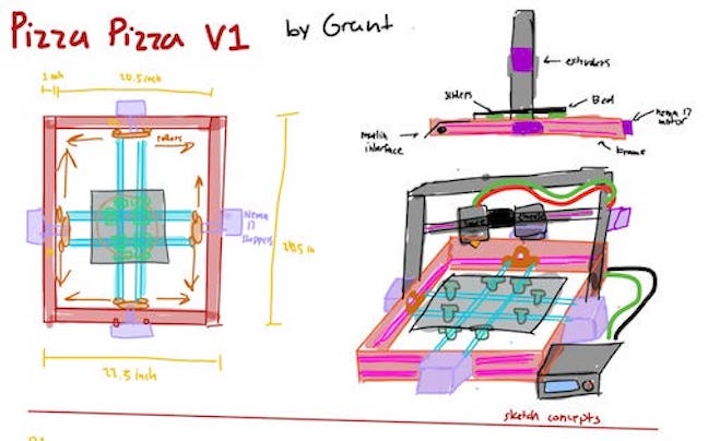
A sketch of what the finsihed machine could possibly look like inlcuding parts labled and color coded throughout the other sketches.
Above is the final sketch of what we believe our pizza preparation machine would look like minus the bed, belts, extruder, and electronics. These parts would all be imported by group members as we completed them. The 3D render above of the machine was completed by groupmate Graham Smith and features corner pieces connecting the frame of aluminum extruder rods. The corners would be 3D printed. The axis of the machine itself would slide on 2 trolleys on the top part of the machine as seen in the design. The electronics and PWM will be stored on the side of the machine as well using the Marlin interface created by Teddy. The machine will also feature tool swaps done by Charles De may. I will be creating the bed at the bed of the machine that the pizza will be on top of as well as a case for the power supply.
Parts List
Above is a completed parts list of the quantity and price of each part we suspect we will use in the creation of our machine. Each part has a link to where it will be purchased from. This spreadsheet includes the aluminum frame rods, LCD displays, motors, and everything else needed to create the machine. Once we have printed the files and acquired the parts we will be ready to construct the machine.
Contribution
In order to aid my group in completing this week’s machine design project I helped in multiple different ways. As soon as we decided upon creating a pizza preparation machine, I sketched up some concepts to get the ball rolling. I detailed each part as well as some more general ideas such as trolleys to move axes that we did end up using. I also used CAD softwares to design and create parts for the CNC machine. I created an AC power cable mount using Fusion 360 that I have documented below. I also created a power supply case that was shaped like a slice of pizza and featured kerf bending using laser cut wood. I aided the organization of the machine by helping in wire routing through my cases as well as electronics mounting. Finally I created the bed for the machine on which the pizza would be prepared. In doing so I also created a removable bed concept which allowed the pizza to be prepared on a removable baking sheet that could be transferred directly to the oven. Overall I aided my group in the completion of this task and further documentation can be found on my site and in depth documentation about the project as a whole can be found on the group site linked above.
Bed
To begin my work on the bed plate I first thought of Ideas that would be both creative and functional. I decided to look sleek with the design. I would create the bed plate out of acrylic and laser cut it. Another idea I would implement into the creation of the bed plate is a hole so that the pizza can be prepped on top of a removable baking sheet so the pizza can be easily cooked directly after being prepared. In the file I first created parameters for each measurement I needed for the plate such as frame dimension, screw size, pan dimensions, and corner rod dimensions. I then created the basic square of the bed. The next thing I added was the circular hole in the center. This circular hole is just smaller than the size of our 14.5x14.5 inch pizza dish so that the lip of it can rest on the bed allowing for easy transfer and cooking of the pizza. The next step I did was add the cut outs to the corners so that the base plate would rest on the frame and fit around the connectors in the corner. I had to measure the pieces to find these dimensions then set them using parameters. Finally the last step I did to complete the bed plate was adding screw holes so that we could attach the bed plate using T-nuts to the aluminum rails. In order to do this I found the distance to the middle of the slot in the rail then created a circle that is parametric that I could change later but would remain in the correct position. I will cut this piece out and mount it to the machine.
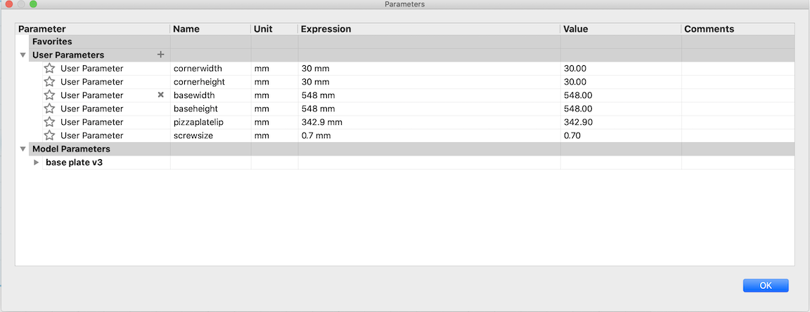
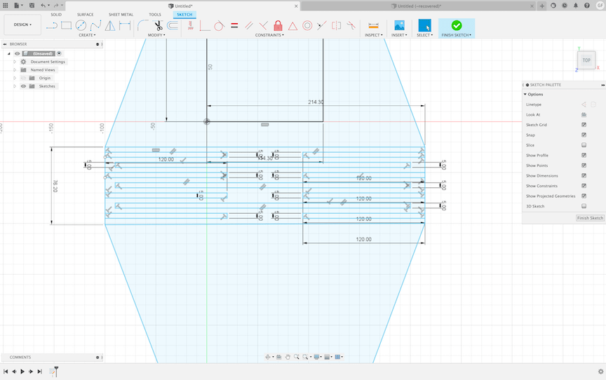
Above are all the measurements I used to create the parameters for the bed plate design. Each one of these could go back and be edited in case our group made any changes to the design that would affect my bed plate.
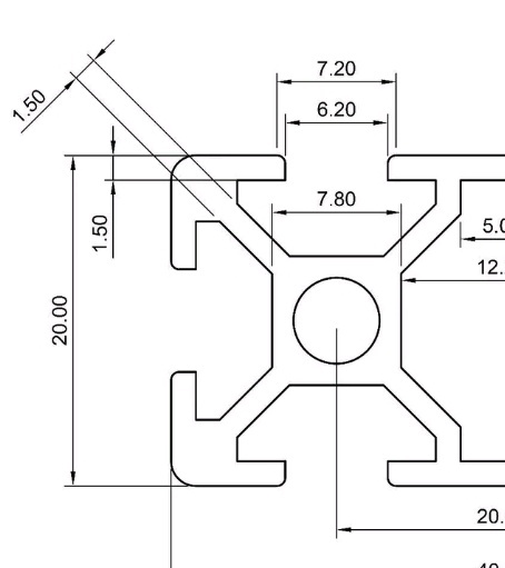
Above is the data sheet that I used that described each measurement of the aluminum extrusion rails. I used these measurements to create the screw holes that would connect to the T nuts to fasten the bed plate to the frame of the machine.
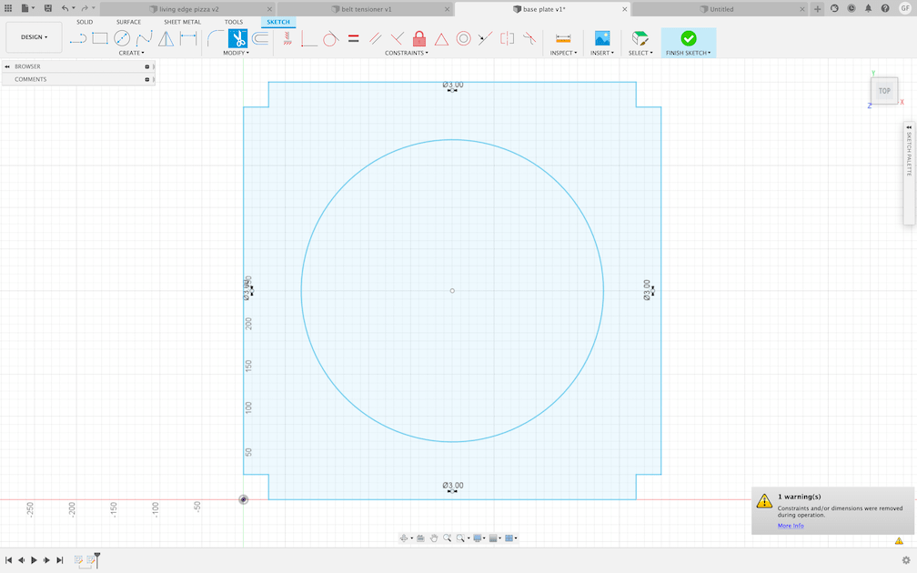
Above is an image of the 2D sketch that would become the final bedplate design. This design features the correct measurements for each component such as screws, corner cut outs, and circle for pizza dishe. I extruded this design to the width of the acrylic material to see a render of final product before production.
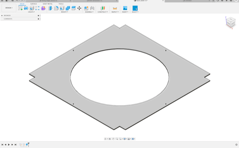
Above is a render of what the final product should look like after production. I added an acrylic appearance since this is what the plate will be created out of. I also extruded the sketch to .125 inches as this will be the width of the material.
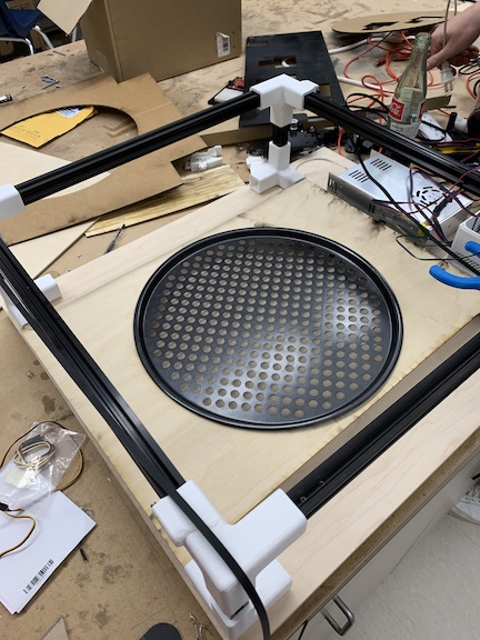
Above is the final bed connected to the partially assembled CNC machine. I had to modify the design to accommodate a lack of aluminum extrusion rails. We were missing two rails across from each other. We also lacked 1/8th inch plywood. I was able to shave off the tabs on the two sides with no rails so the bed would still fit but I was able to cut it on the small amount of 1/8th remaining. I also attached the baking sheet into the hole in the bed so that it rested by the lip and was able to be removed for easy cooking and transfer.
Power Supply Housing
Attempt 1
In order to encase the power supply for our pizza CNC, I attempted to create a pizza box with a living edge. Through creating this design I learned a lot as I had never before created a living edge on any material. I started by designing a fusion file of a triangular pizza box that would utilize kerf bending to form the living edge. I created what I thought would be a living edge by cutting slots into the hinge but after cutting realized this would not work on the wood version of the pizza box. Another problem I realized after cutting was the size of the box. Due to the size of the power supply I ran into size problems as in order to fit the large rectangle in a triangle the triangle had to be very large. I will make some changes to the file before cutting the wooden version.
Above is an image of the living edge I created on my first try. I realized after cutting that I created the lines too far apart and too wide. I would change this error before creating the second version of the living edge pizza box.
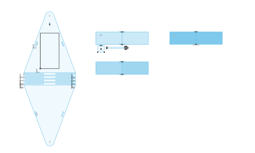
Above are all the components in the file for the power supply case of version 1. I have the pizza box with the hinge to house the power supply. This part also has slots to connect tabbed side pieces and a piece that will have a rod go through it to connect side pieces to case to make the box more sturdy.
The image above shows the cardboard pizza box after running the file. I noticed an error with the distance between lines on the hinge and here is where I realized sizing would be an issue otherwise the file worked in every way I expected it to. I will need to make changes though before creating the final version.
Failures
Overall after creating this first test I learned a lot but also realized many errors I would need to correct. For starters the living edge was far too spaced out to ever be able to bend wood. Before cutting on wood I needed to perfect my kerf bending and in order to better learn I did some research. Another error that I need to correct is the size of the box. Although the box houses the power supply it is very large. This would greatly cluster up our CNC machine. All of these issues would need to be fixed before creating the final product on wood.
Attempt 2
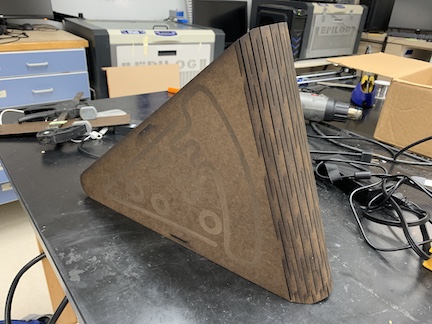
For attempt two on creating the power supply case with the living edge I changed my design a bit. First after seeing the problems the old living edge would cause when cutting on wood I reamped the pattern into one I saw commonly used with examples. I added much more lines instead of rectangles so that the wood would bend with a better curvature. Once I completed the living edge in a way that I believed would work, I improved the cable management by adding a hole for cable routing. Finally to improve the design I added an engraved pizza slice image for a bit of personalization. I will cut this pizza box as soon as the laser cutter in our lab is fixed. I will mount the power supply in this box and then mount the pizza box vertically on a section of spare wood connected to the CNC bed frame.
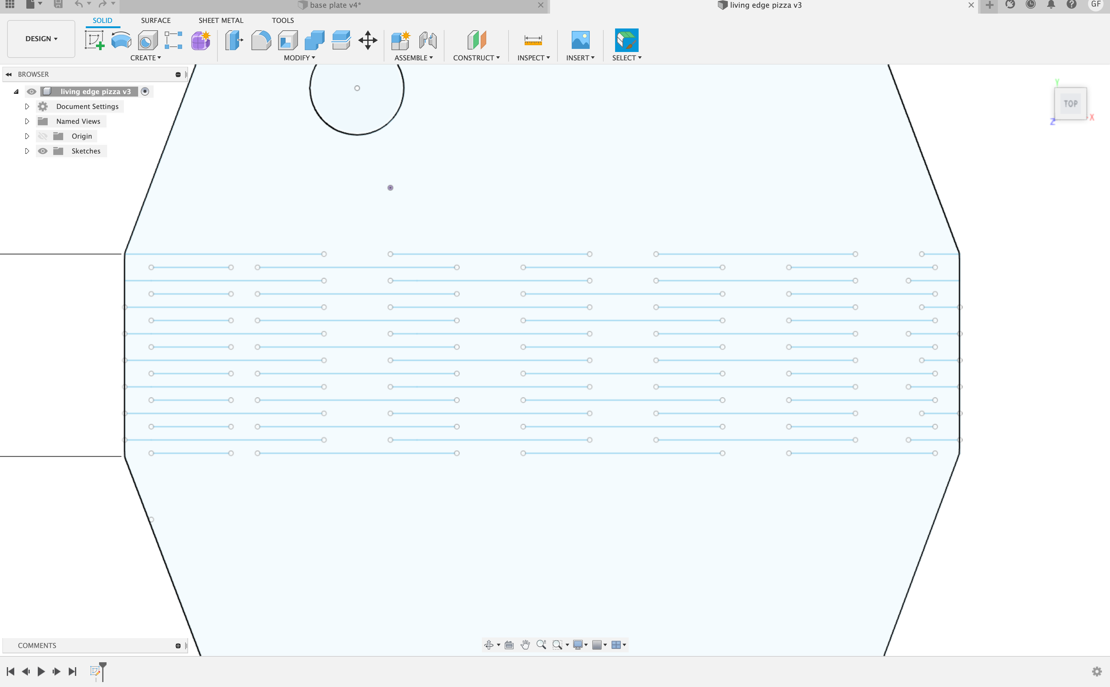
Above is an image of the new variation of the lines that will form the living edge. I fixed the old design which was a bund of rectangles that were staggered and replaced this by adding much more lines. This design allowed our group to bend wood for the pizza box.
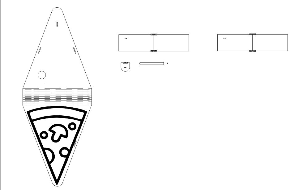
This is the version two of the entire file. Changes have been made to the main box portion with an improved living hinge, better cable management, and a personalized pizza svg that will be engraved into the power supply case.
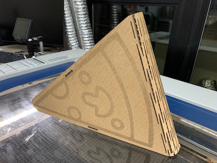
Above is a test cut I ran of the power supply pizza case. I tested the new living edge on cardboard first using imported settings on the lab’s laser cutter. I assembled the case and everything worked. The kerf bending was much stronger and more stable.
Before I committed to cutting the pizza box on large amounts of wood I first trimmed the side panels off the file and cut the small portion of kerf bending on the wood to see if the revamped design would even work. I learned alot from this as I never previously had tried kerf bending. I decided I should add more to have a gentler curve for the pizza box then I would cut out of wood.
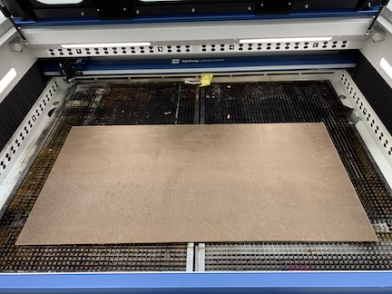
Due to the size of the file I was trying to cut and the shortage of wood I had to look towards other 1/8th inch materials that I could use. After a bit of research I decided I would be able to use fiber board, the material used to create clipboards as it shared similar properties to wood and used the same settings. I tested by running the small pieces before the actual living hinge to see if it worked.
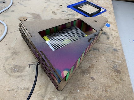
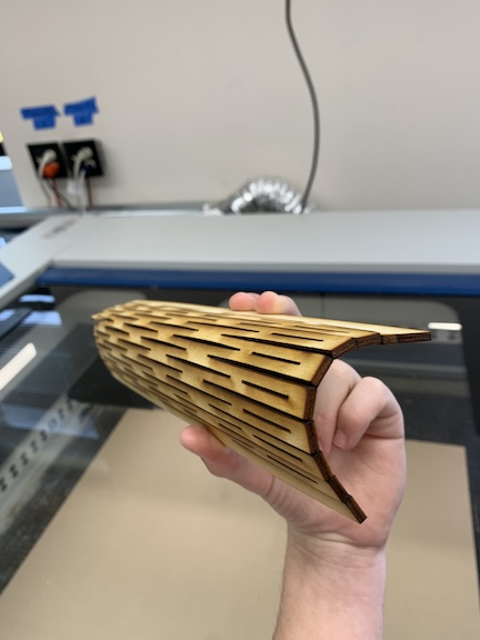
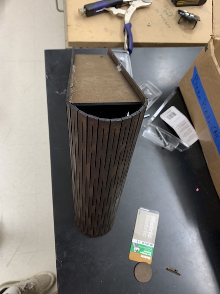
This is a photo of the completed pizza box utilizing the living hinge. It would either slide over the vertically mounted power supply and rout cables out the side or be a separate entity containing the power supply. I connected the tabs on the upper and lower to one sidewall allowing it to slide over the power supply. As you can see the kerf bending worked perfectly and the new wood posed no problems.
Above is a photo of the curve that the living edge gave me. Unlike the tests in attempt 1 and the first living edge test on wood, this design gave me a very gentle curve. The wood was very bendable and did not appear to be under any substantial stress.
AC mount
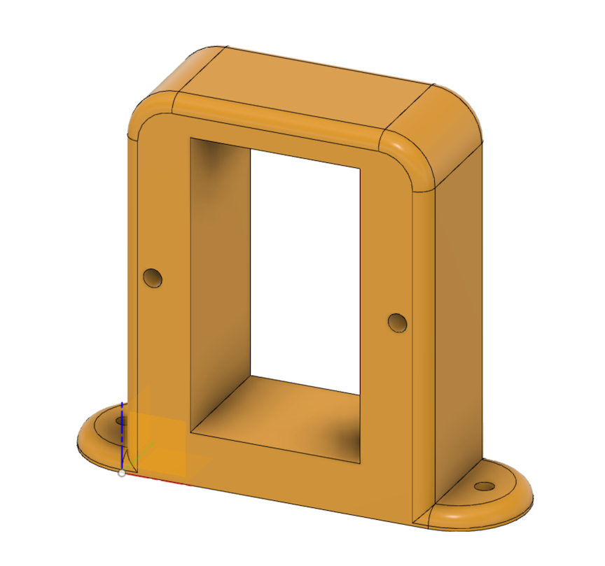
Above is a photo of the file I used to print a case for the AC power cable. I used a caliper to obtain precise measurements on the power cable to make the case best as possible and all measured the screws we would be using to create mounting screw holes. I added a fillet to make the case flow smoother and look better with the overall design. This holder had to remain accessible as the switch would be responsible for turning the machine on and off.
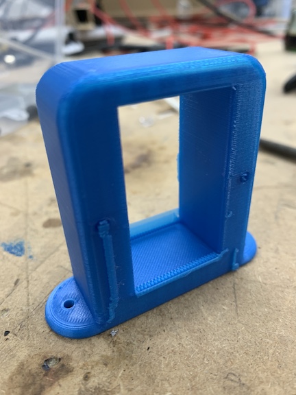
This is the raw 3D print after I had just removed the supports. Everything looks successful and there are no imperfections. I now will attempt to mount the AC power cable to the case and make sure that everything fits tightly.
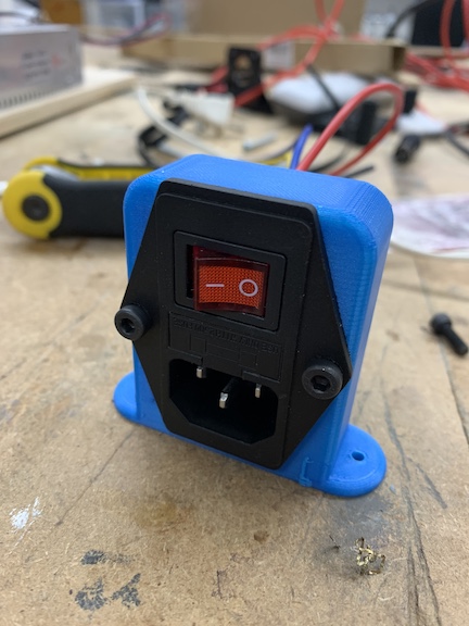
This is the final of the cable holder. The cable has been screwed in and fits smoothly.It has not yet been mounted as I am figuring out how to neatly organize the cables but once this is completed I will screw down the case. This case will mount close to the power supply as it needs to connect.
Final Product
A video of the pizza machine in action featuring tool changing, extruding the pizza condiments through servo control, and overall a working machine.
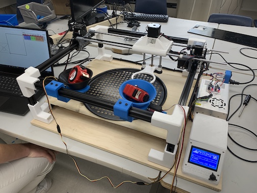
Above is an image of the final product from machine week.The machine itself does not deviate much at all from the render above. The CNC machine was assembled using 3D printed connector pieces with aluminum extrusion. The machine uses V rollers created by Graham smith and to move the x axes and belts to move the z axis. The pizza preparing machine is capable of homing and locating itself thanks to the end stops Teddy placed along each axis. Teddy Warner was also responsible for the Gcode controlling tool change which our machine featured as well as the Marlin interface. The interface tracks the tool end position with X, Y, and Z coordinates. The tool changes slots in with the extrusion rods and allows the machine to grab the hoppers and lay down either sauce or cheese along the figure of the pizza thanks to a program written by Charles. The gantry has a circular clip on it capable of picking up each hooper which has a servo controlling whether or not the condiments are benign extruded. An interesting thing designed by Graham was the use of spacers on the V rollers. One of the V rollers did not align with the slot rail so he designed spacers on the laser cutter to align them. Overall after implementing the code and assembling the machine we are now able to prepare a pizza.
Summary
In conclusion to this week’s assignment I learned alot about machine design. I especially learned alot about the motion assembly and the level of precision required when assembling the gantry and the v rollers on each axis. Our group ran into numerous problems with these trolleys not being aligned which caused more problems throughout. I think this project aided my understanding of what each component in the machine building process does and how precise they need to be in order for the machine to function properly. I would know this due to how many times I had to re print or cut certain files due to errors that were just millimeters off.