14. Interface and Application Programming
The assignment for this week is to write an application that interfaces a user with an input &/or output device that you made. I will use interface week to create a canvas that when pressed with my mouse, an LED is turned on through software serial.
Group Work
For this weeks group work assigment, our group was designated with the task of comparing different tools for applications and interface programming. I helped my group complete this task by discovering the differences between each of the softwares as I had become familiar with processing during this task. A link to all group work completed can be found on the group site here.
Processing
To start this week off I first looked into some possible softwares that I could use to connect to a processor on an input or output board that I created. After some research I found the software, processing, which I could use to complete this week’s assignment. Processing allows me to connect to the processors of the chip and write code that acts upon the functions in my arduino code. I first had to download the processing IDE. I want to create something that allowed me to press a canvas that I created in processing that would then send a serial value to a blink board I created and light it up.
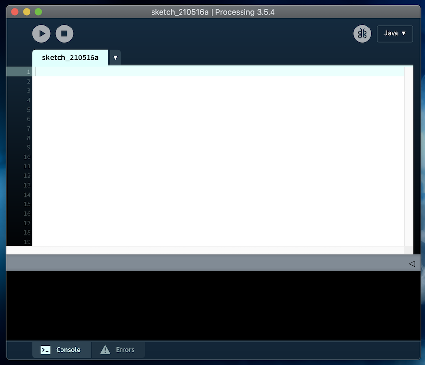
Above is an image as soon as I opened the processing application. I noticed it looked very similar to the arduino IDE. Here is where I will begin to code my interface.
Prior to this week’s assignment, I had never used processing before. The first thing I did before attempting to write a code was watch a tutorial on how processing worked. This would better my understanding of the program as a whole and allow me to better troubleshoot issues in my code as they appeared.
The first thing I did when I started my processing code was setup the serial. I used tutorials when I encountered problems but after numerous tutorials regarding processing, it became straight forward. I then had to set up the size of the canvas I wanted to draw. When I finished the code, I clicked run and saw the gray canvas appear. When I pressed the canvas with my cursor, a serial value “1” was printed. This is exactly what I wanted to happen with my code function of mouseClicked. Now I must write an Arduino code for my 412 blink board that reads the serial values sent by processing and turns on an LED.
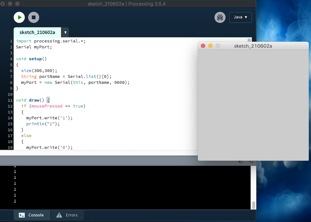
Above is an image of the processing in the background and the canvas that was printed resulting from my code. As you can see in the bottom of the processing window, the serial value 1 has been printed indicating that my code is doing what I want it to be doing. I now am going to code my 412 blink board to read this serial value and turn on an LED.
Learning
In order to learn procesing, I first refrenced the examples given to me by the processing application. I learned through this how to create canvases as well as linking the processing code to the arduino code. I then further advanced my knowlege of processing by watching a tutorial about how to use serial values to communicate with a procesor running arduino code. Below is a link to the tutorial that helped me learn my way around the application.
Code
import processing.serial.*;
Serial myPort;

void setup()
{
  size(300,300);
  String portName = Serial.list()[1];
  myPort = new Serial(this, portName, 9600);
}

void draw() {
  if (mousePressed == true)
  {
    myPort.write('1');
    println("1");
  }
  else
  {
    myPort.write('0');
  }
}
Arduino Coding
After getting my processing code to work and send a serial value, I now have to write a code in arduino for my 412 blink board that will read the serial values sent and determine whether or not the canvas has been pressed to turn the led on or off. I am going to have to utilize the RX and TX pins on the 412 so that it can read the values sent.
#include <SoftwareSerial.h>

#define RX A1
#define TX A2

SoftwareSerial mySerial(RX, TX);

char val;
int ledPin = 0;

void setup() {

pinMode (ledPin, OUTPUT);
pinMode (RX, INPUT);
pinMode (TX, OUTPUT);
mySerial.begin(9600);
}

void loop() {

if (mySerial.available())
{
  val = mySerial.read();
}
if (val == '1')
{
  digitalWrite(ledPin, HIGH);
} else
{
  digitalWrite(ledPin, LOW);
}

}
Above is the completed code that I used for this weeks task of using interface with an input or output board that I created. In the code I first had to set 2 digital pins that would become my TX and RX in software serial. Then I had to set the LED pin value as well while refrencing the 412 pinnout. Finally, I wrote the loop stating that if serial data was available (sent from processing), then it would read the integers and if it was a 1 sent over the LED would blink.
Final Video
Above is a video of my interface running while using processing. I had to upload the arduino code to the blink board using an Arduino UNO programmed with Jtag2UPDI. Once this was completed I switched to an FTDI board becuase I needed to send and recive serial data. Once this was completed I closed out all connections to the COMM port in Arduino and ran my processing sketch. A grey box appeared and when pressed sent a 1 value to the serial monitor of the blink board. The code that had been uploaded to the blink board turned on the LED with each press of the canvas as displayed by my video.
Summary
In conclusion, this week was informative and taught me something I had never known before. I was intrigued by the ability to send serial daat based upon pressing a button that I created with a code in the processing application. I encountered little failures during this week’s task outside of not closing all my Serial connections other then processing beforehand. I corrected this error becuase a message displayed stating how I can not have multiple serial connections.