4. Computer-Controlled Cutting
updated (4/2/2021): Based on feedback, I am updating this section to note that I am completing my Fab Academy group assignment work independently since I am a remote student with Charlotte Latin. All the documentation work is being done at the Haystack Fab Lab in Deer Isle, ME.
Laser Cutter
The first part of this assignment was to characterize our laser’s focus, power, speed, rate, kerf, joint clearance and types. Our lab has two machines, a Universal VLS6.75 and a VLS3.60. We recently purchased the VLS6.75, and I have not used it a lot so I will use this machine to characterize these settings.
Laser Cutter Characteristics
| Machine | VLS6.60 |
|---|---|
| Power | 60W |
| Size | 32” x 18” |
| Lens | 2.0” |
| Kerf | 0.1mm |
Universal VLS 6.60 Laser Cutter User Manual
Cutting Cardboard
Material: 3/16” Corrugated Cardboard
- Power: 98%
- Speed: 22%
- Frequency: 500PPI
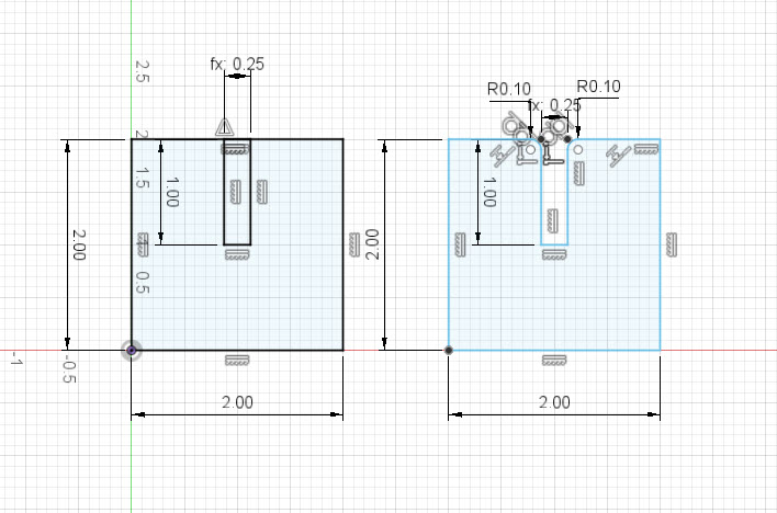
In Fusion, I used the parametric design tool to create two variables (materialThickness and laserKerf). The slot for the joint was set to the following expression: materialThickness - laserKerf*2. The laser’s kerf is doubled because the joint has two sides and so the laser will cut and remove material from other side, doubling the total material removed.
- materialThickness: 4.0mm
- laserKerf: 0.1mm
I went through several tests on the cardboard to establish the correct power and speed settings, as well as the tolerance required based on the laser cutter’s kerf and the cardboard thickness.
The cardboard joint was a tight fit, possibly too tight. I could adjust the materialThickness parameter to 4.1mm to make everything to loosen the joint. But overall, I was happy with how it came out.
Press-fit Construction Kit
Concept
For my press-fit construction, I decided to make a snap together train track for Lucia’s Lego Train set. The idea would be to have three different pieces that can fit together and be assembled to form different track sizes and shapes.
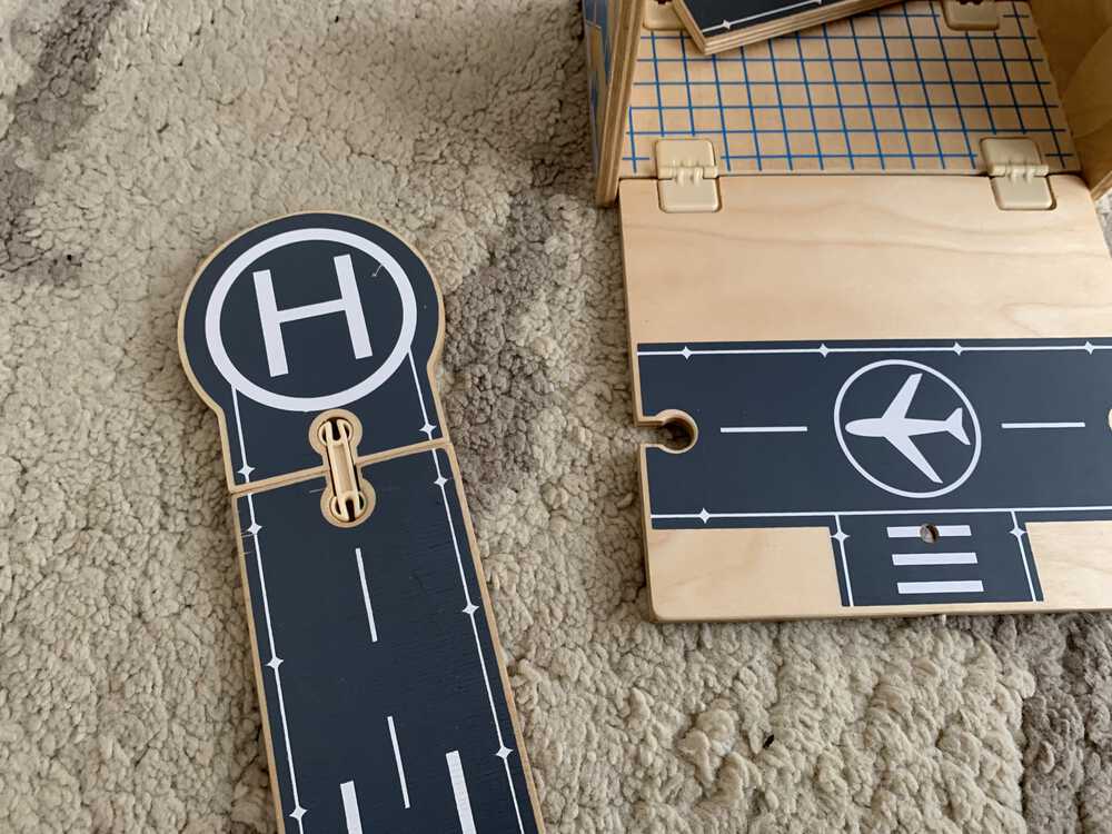 I got the idea from a kit that we purchased from a thrift store last week. They used a clever clip to connect the track pieces and I wanted to see if I could develop something similar for Lucia’s Lego set.
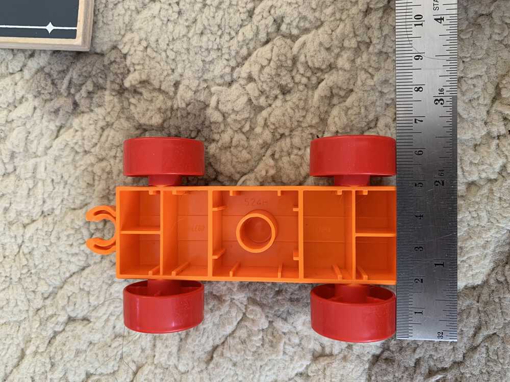 I started by taking measurements of the Lego train piece. Importantly, I need to know the wheel size and the axle length, or the distance between the left and right wheels.
Design A
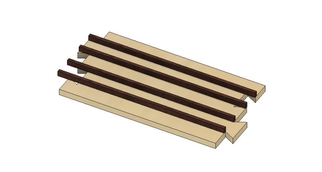
For my first attempt, I designed a track system using Fusion 360 and intended to use the laser cutter to engrave the tracks into the pieces.
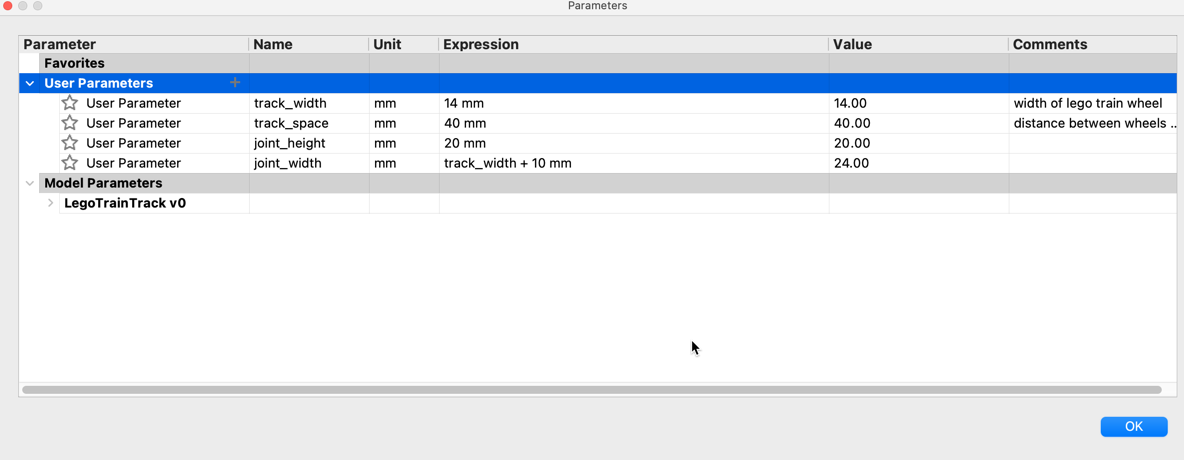 I integrated Fusion’s parametric design by setting the track width and spacing as variables. This would allow for quick design updates if I did not measure the Lego train set properly, or if we wanted to adapt the track for a different type of toy, like a car that had a different wheel and axel size.
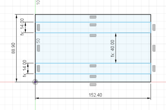 In my sketch, I used the dimension tool to input the parameters that I defined above. Fusion makes using parameters in your design fairly easy. You simple start typing the name of the variable and a pop-up menu will appear and shows you a listing of all the variables names that you have access to.
 I decided to laser engrave the track channels into the plywood. This meant I had to export the design to Adobe Illustrtor and fill in the track rectangles with RGB Black (0,0,0) so the machine would move remove all the material within the rectangle.
| Material | 1/4” Baltic Birch Plywood |
|---|---|
| Enraving | Settings |
| Power | 100% |
| Speed | 20% |
| Cutting | Settings |
| Power | 100% |
| Speed | 8% |
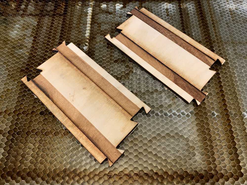
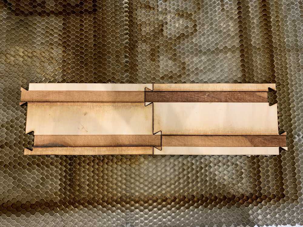 To my surprise, the joints worked really well. You can only attach the piece by pushing them into vertically. This means when Lucia is playing with the pieces on the floor, they can’t easily come apart. I also like the dovetail look of the joint. It is not your typical finger joint/box joint that is so often done on the laser cutter. I wish I had tried to make the joint spring-loaded so that it would snap fit, which I may do for a future project.
The results were mixed. While the joint pieces snapped together and the dovetail shape seemed to work well, the track rails took too long to engrave (about 5 minutes per piece). They also were not sized appropriately and so I went back to the drawing board.
Here is an interactive 3D model using the Fusion 360 plugin. You can see the 3D model of the first design of the train track.
Design B
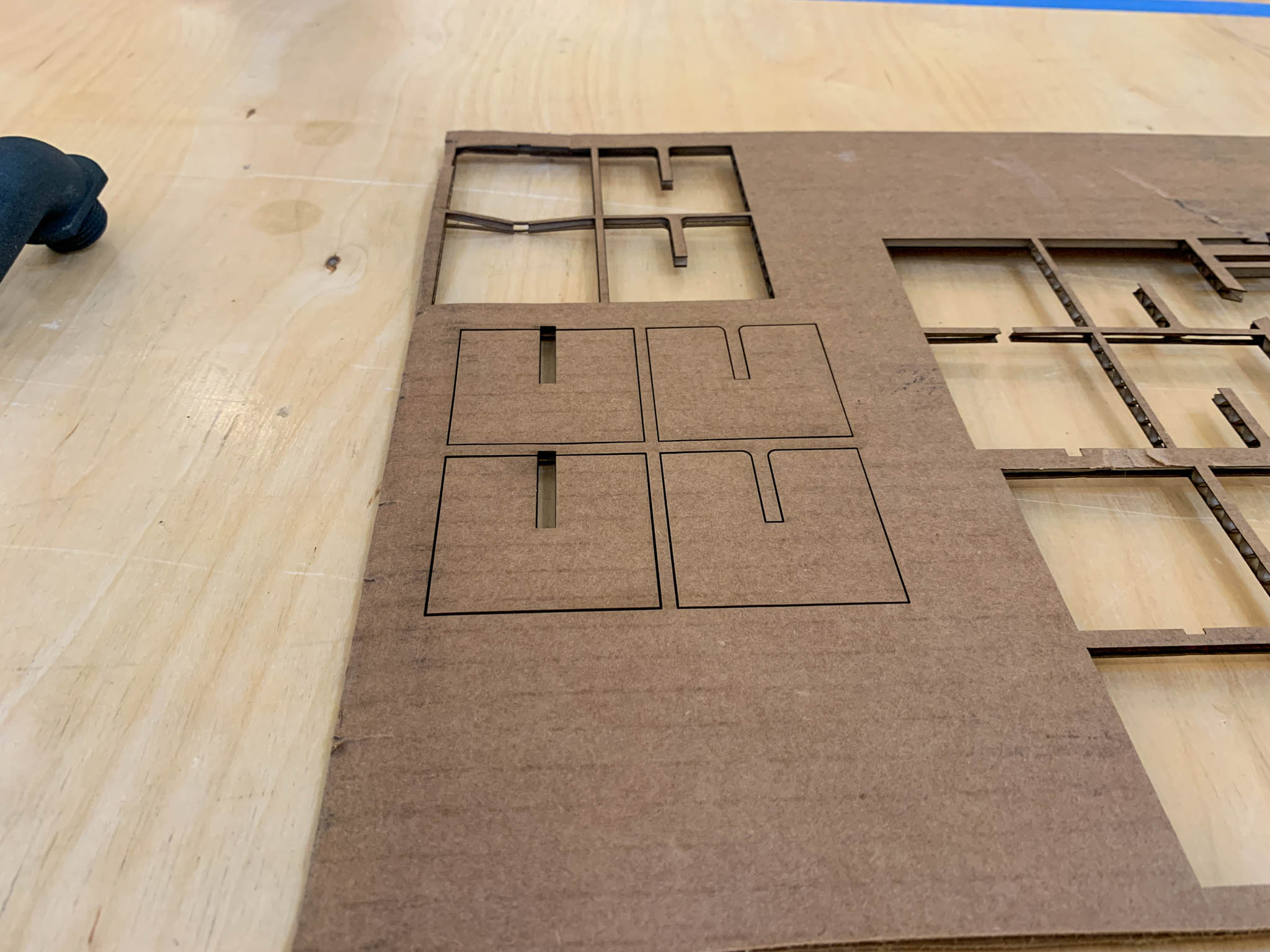
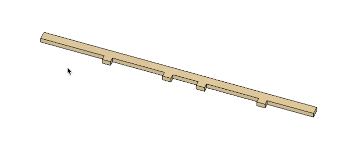
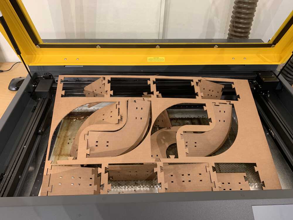
For a re-design, I decided to laser cut small track pieces that would snap fit into the larger track pieces. I decided to prototype this new system using the 3/16” Corrugated Cardboard that I used previously.
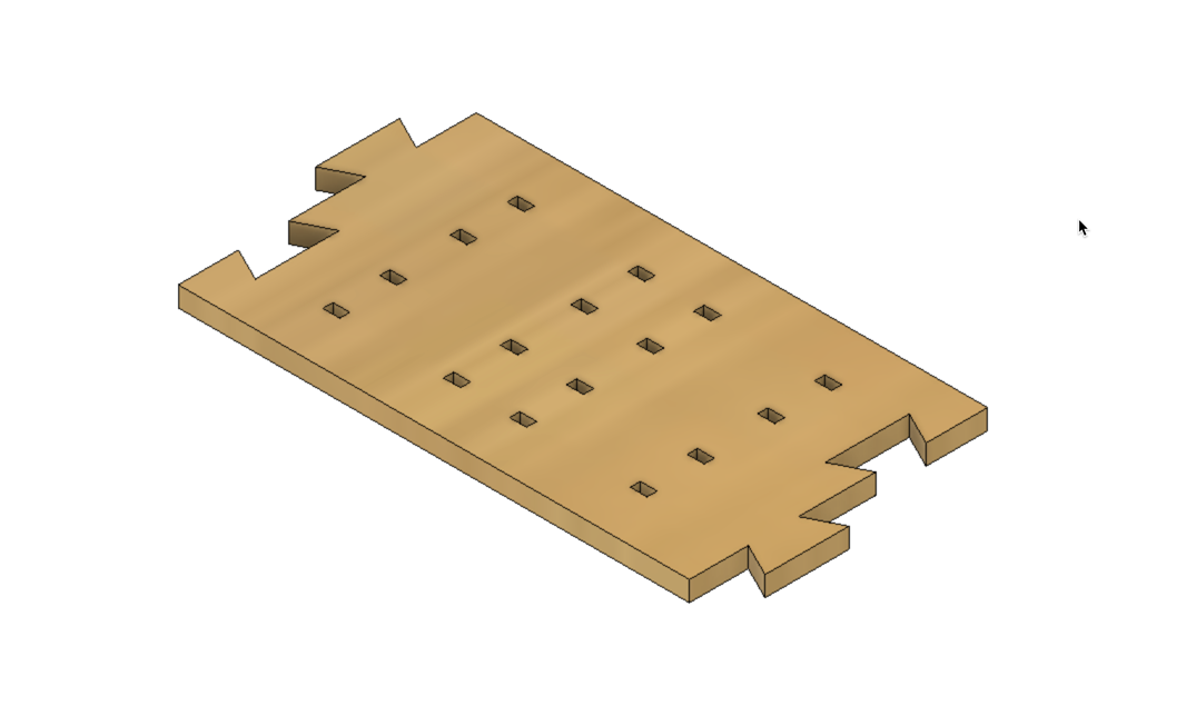 I decided to make box joints along the track to inset cut out rails. I thought this method would be faster to fabricate.
Onto the laser cutting…
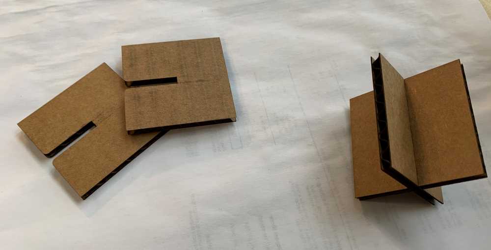
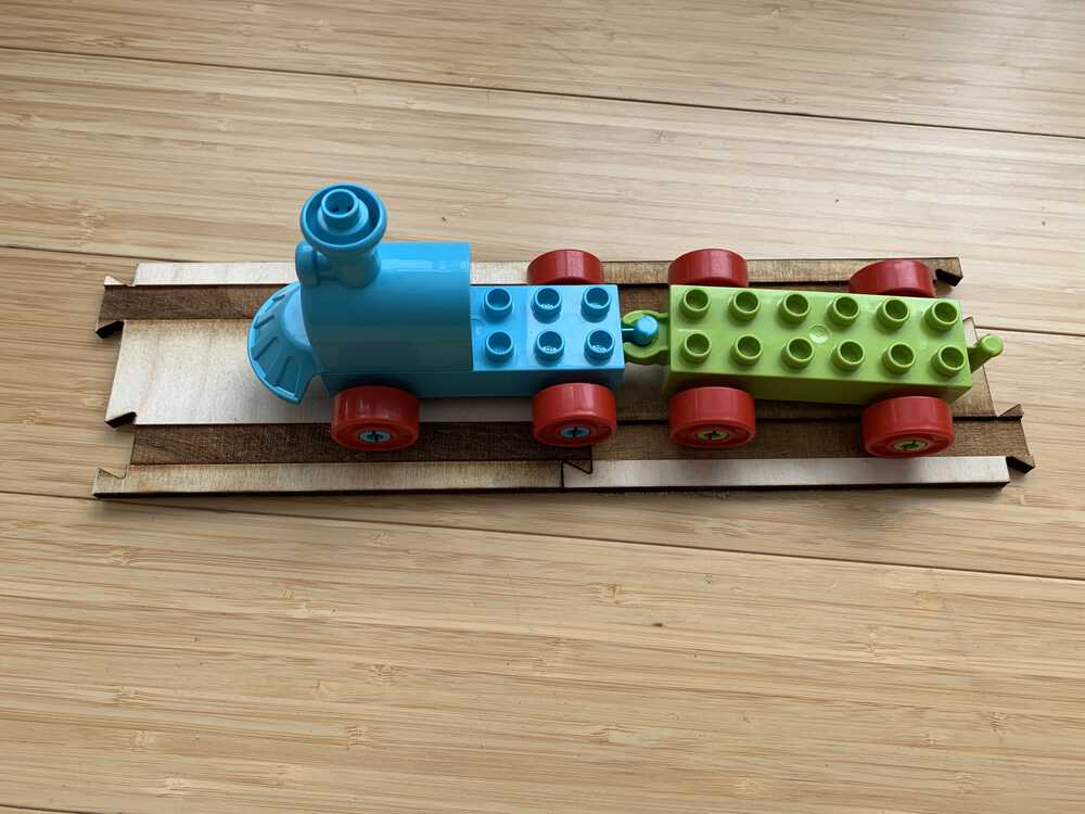
After running a couple of tests with the joints, I made a big batch of parts to bring home and have Lucia play with.
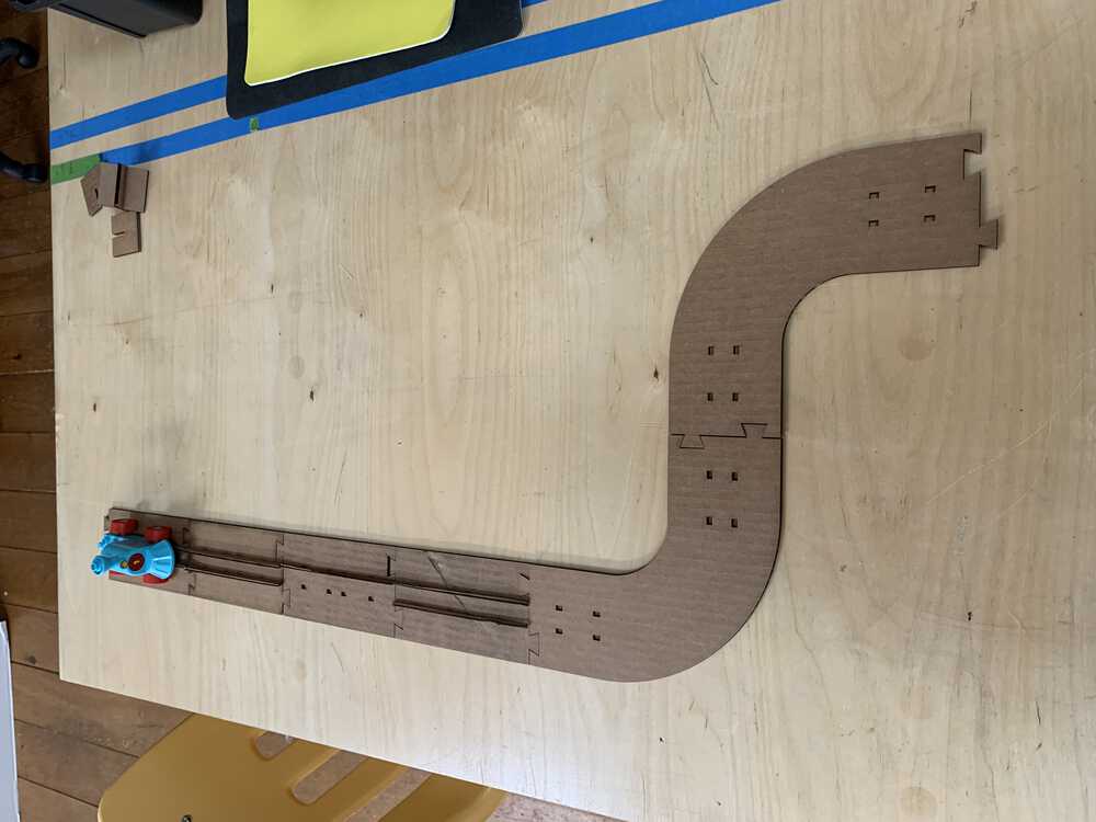
Testing out a quick assembly.
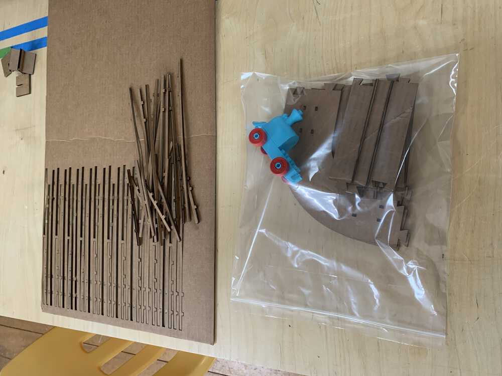
Bagging up the kit to bring home.
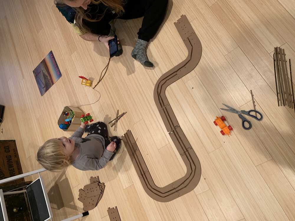
Lucia approves of my laser cut project. She is happy to play with it.
Here is an interactive 3D model using the Fusion 360 plugin. You can see the 3D model of the final design of the train track.
User Testing (Lucia)
Design Files
updated(4/22/2021) added laser kerf joint study file
Vinyl Cutter Project
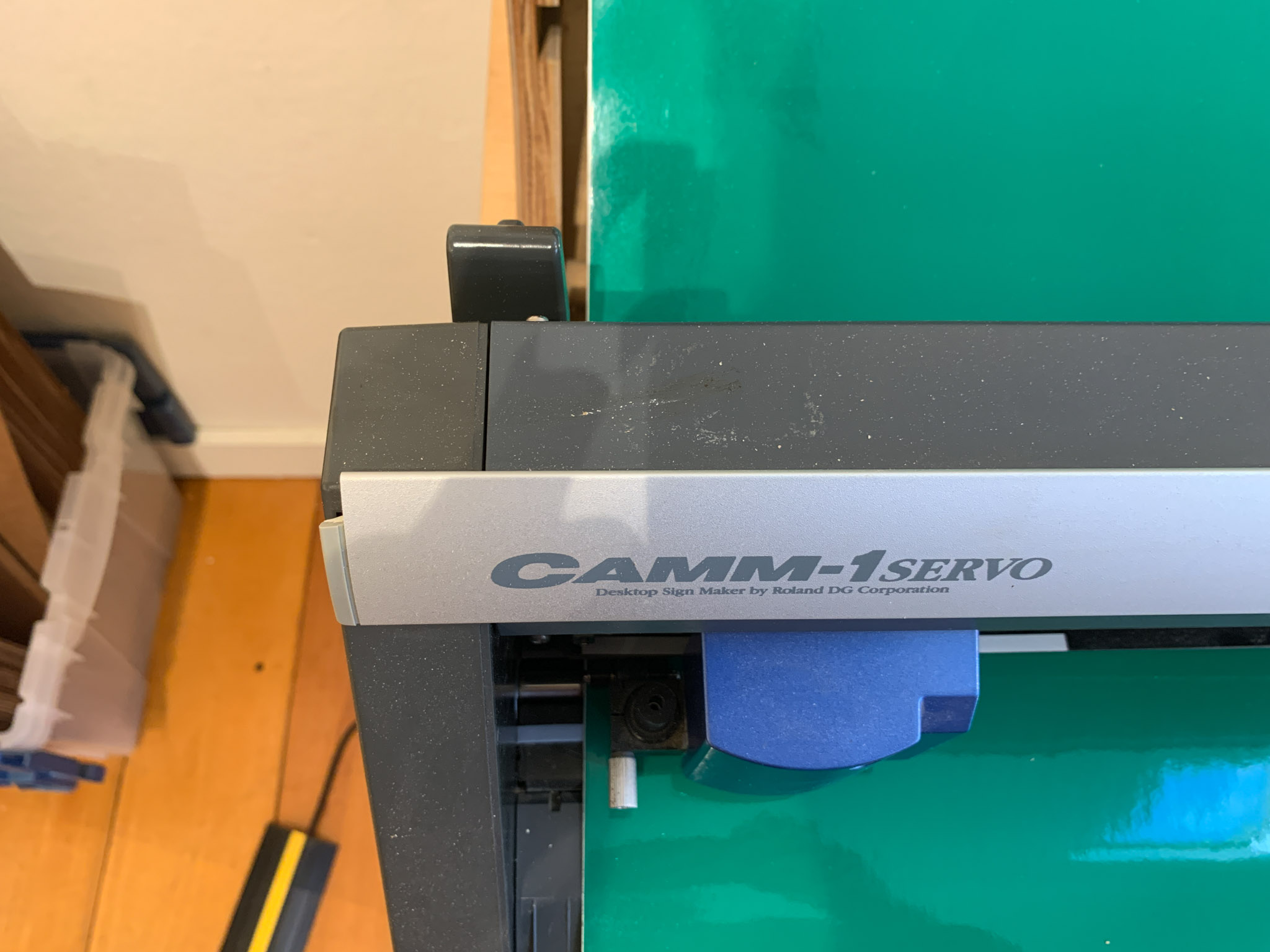
updated(4/2/2021): The vinyl cutter at the Haystack Fab Lab is a Roland GX-24. We use a laptop running Windows 10 and Adobe Illustrator to design and print files to the machine. The designs need to formated properly for the machine to detect cut lines. The format convention is RGB Red (255,0,0) stroke outlines, with a stroke width of .001 pts.
For my vinyl cutter project, I decided to make a decal for the Fab Lab glass doors. There are two large glass doors, so I would like to put a decal on each window. On one, I will put the typical Haystack branding design, and on the other I will put the Fab Lab program branding, which is still a work in progress.
I designed the vinyl sign using Adobe Illustrator. We already had some of the Haystack graphics in vector format, so I just made some adjustments to the layout, scale, and format.
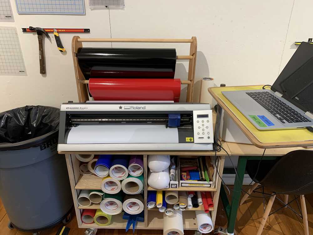
This is our vinyl cutter station at our Fab Lab. It has all the necessary materials and tools, along with a dedicated computer.
Vinyl Cutter Preperation
To get the machine setup, you need to load your material into the back of the machine, pictured above.
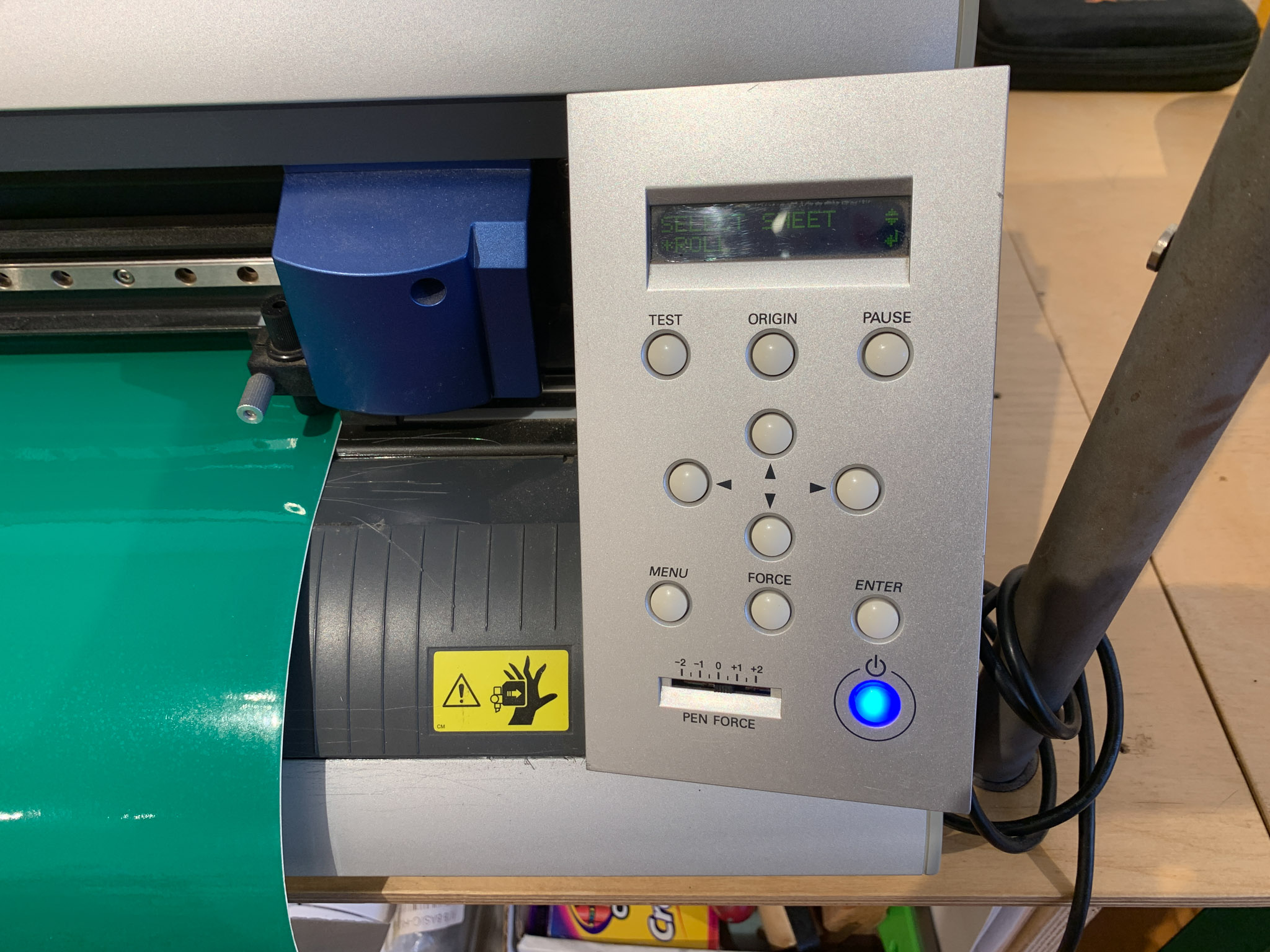
Next, turn on the machine and wait for it to complete it’s boot-up sequence. You can select the enter button if you are using a roll of material. This will measure the width of the material.
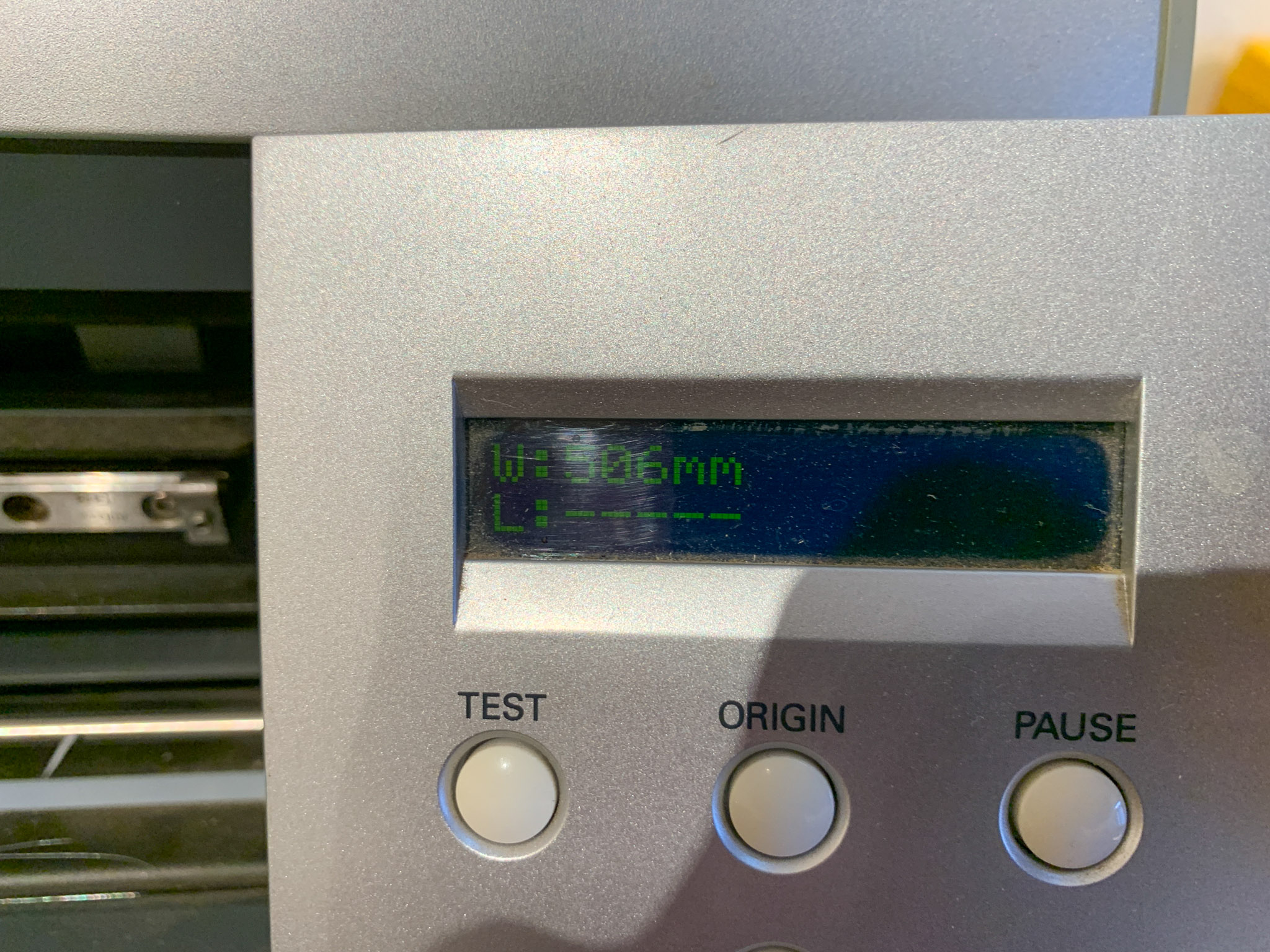
You will need to remember this measurement later in Illustrator to setup the print settings. We use 24” vinyl in our machine and so it usually comes out to be around 500mm.
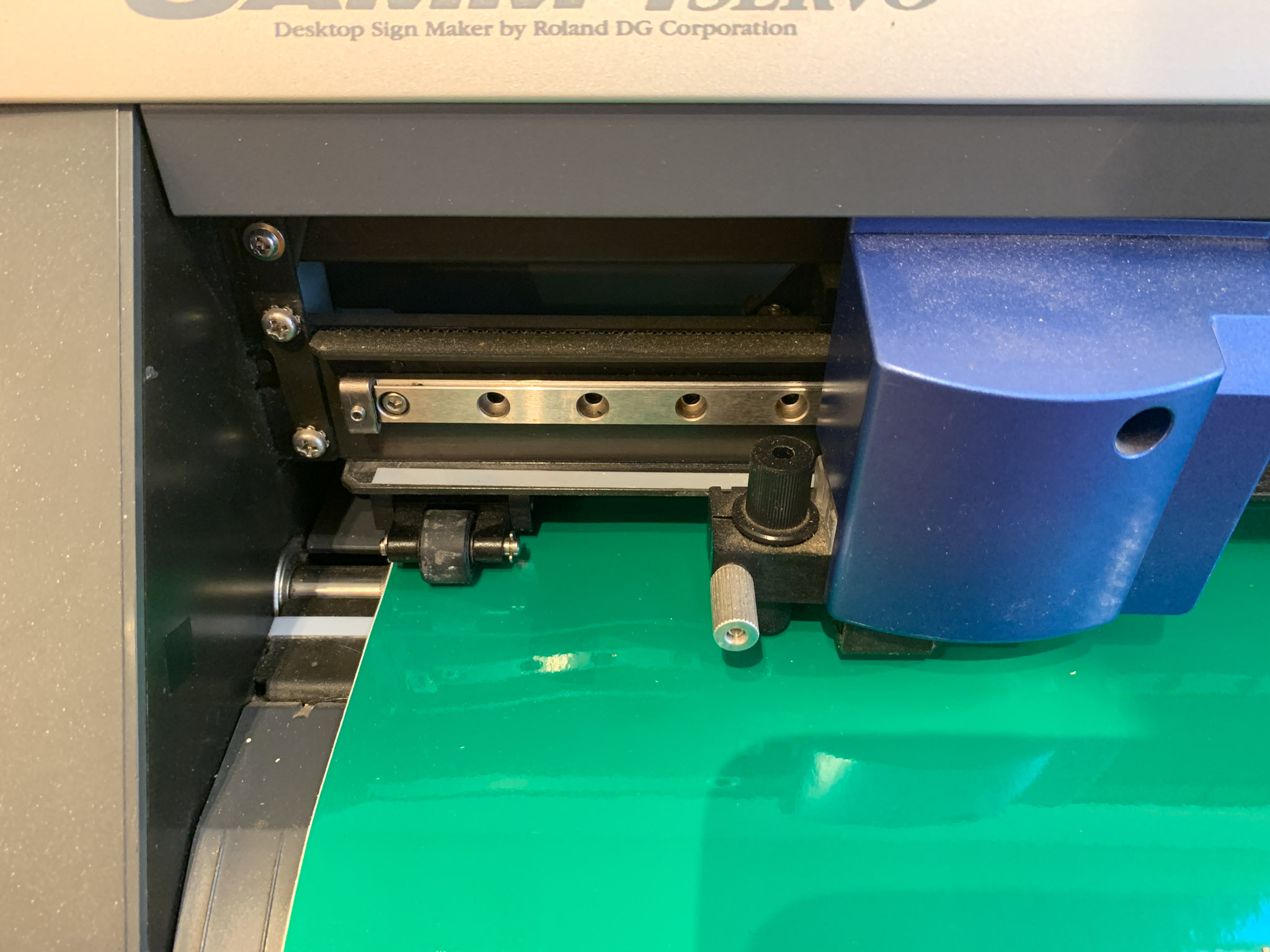
You also need to set the rollers on the machine so that they are located along the white guides.
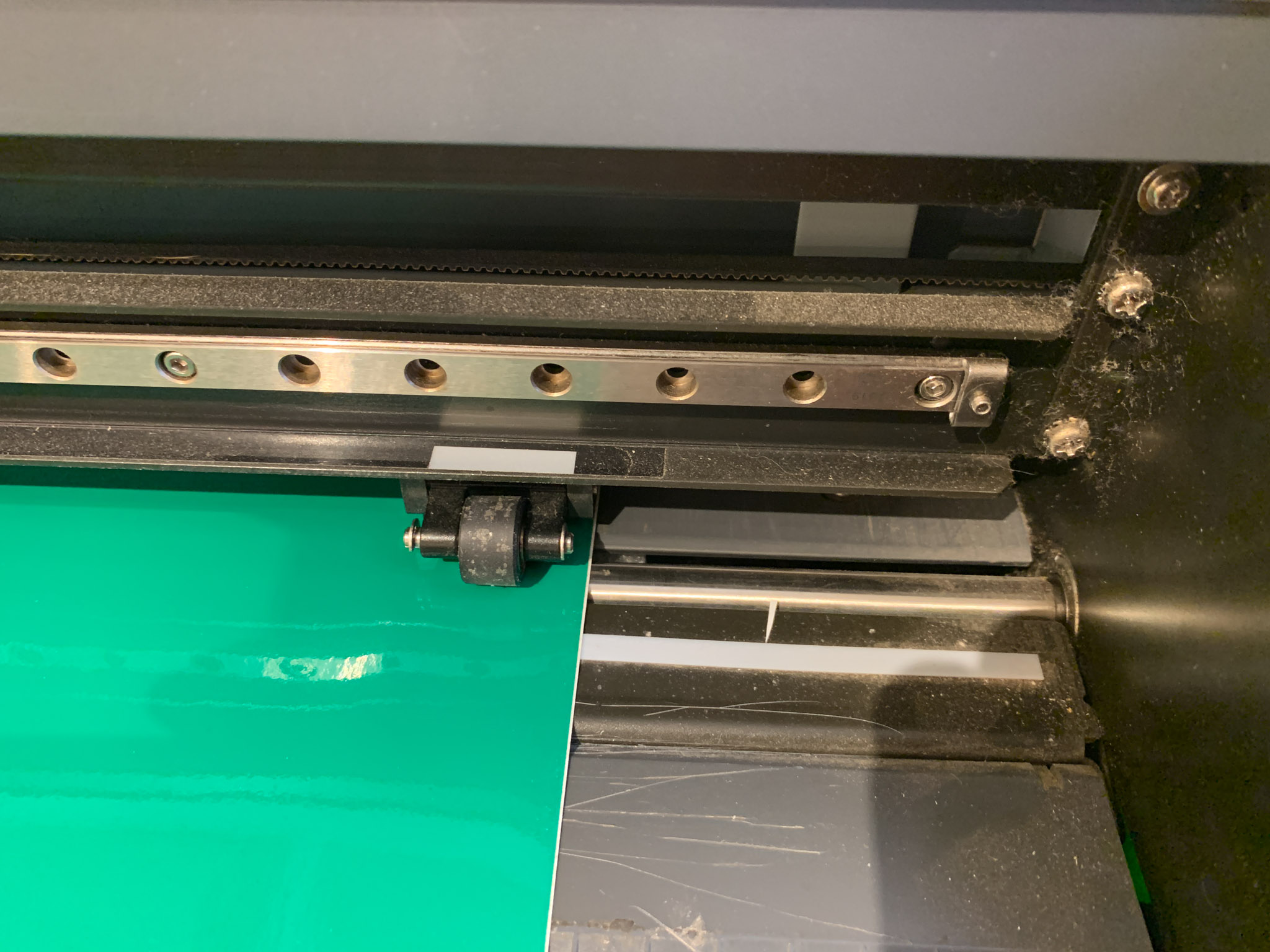
There are two rollers to set, one of the left and one on the right. Set both, and make sure they are located on the edges of the material. This is what will spool your material out so it is important to ensure proper placement.
Finally, there is an adjustment bar in the back to lock the rollers down onto the material.
Illustrator File Preperation
In our lab, we use Adobe Illustrator to send files to the vinyl cutter machine. It is easy to prep files in the program using the following settings and workflow.
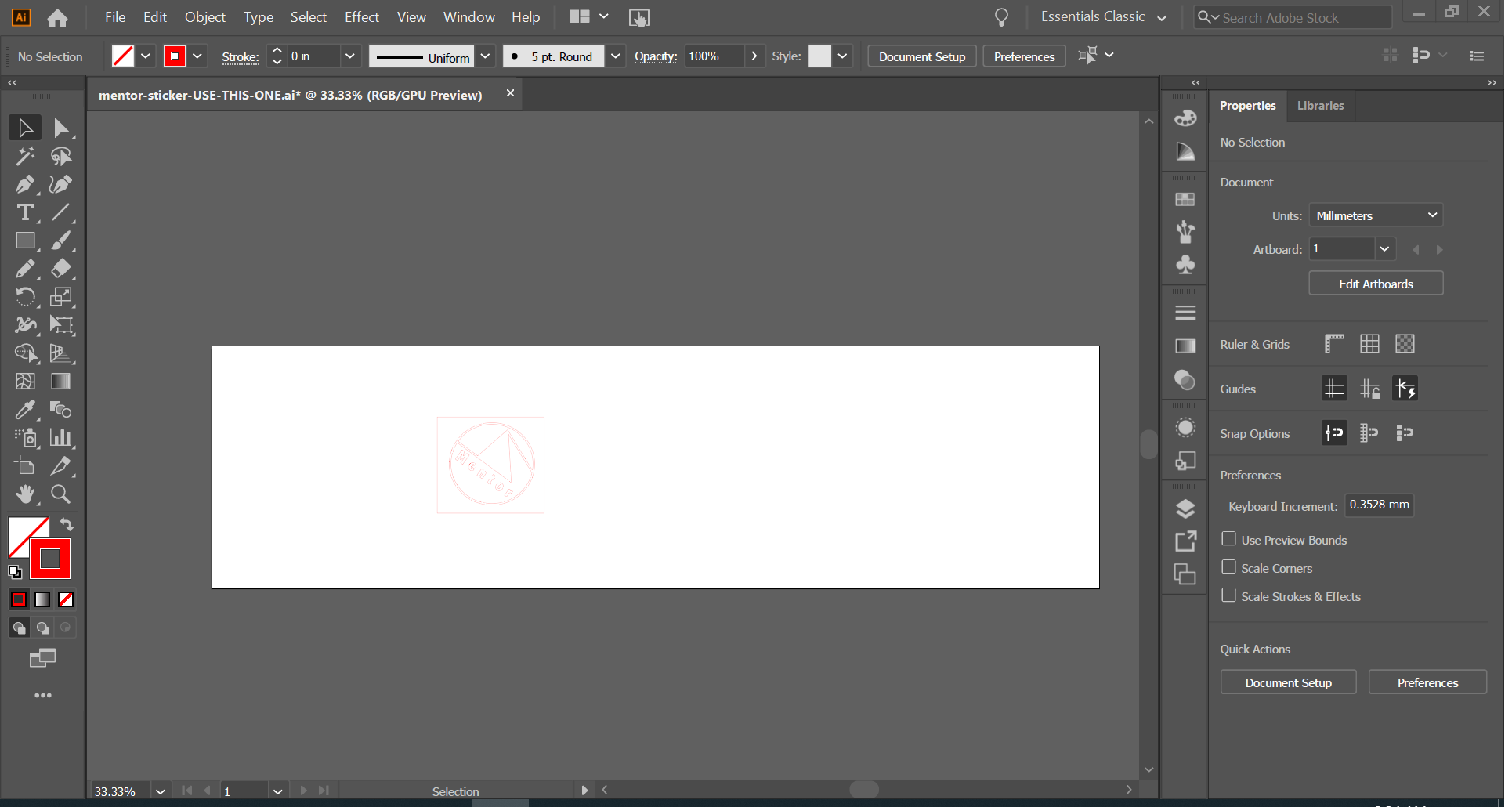
First, you need to format your vector lines as “hairline” strokes by using a .001” stroke width. This will make a really thin line on the screen, sometimes difficult to see.
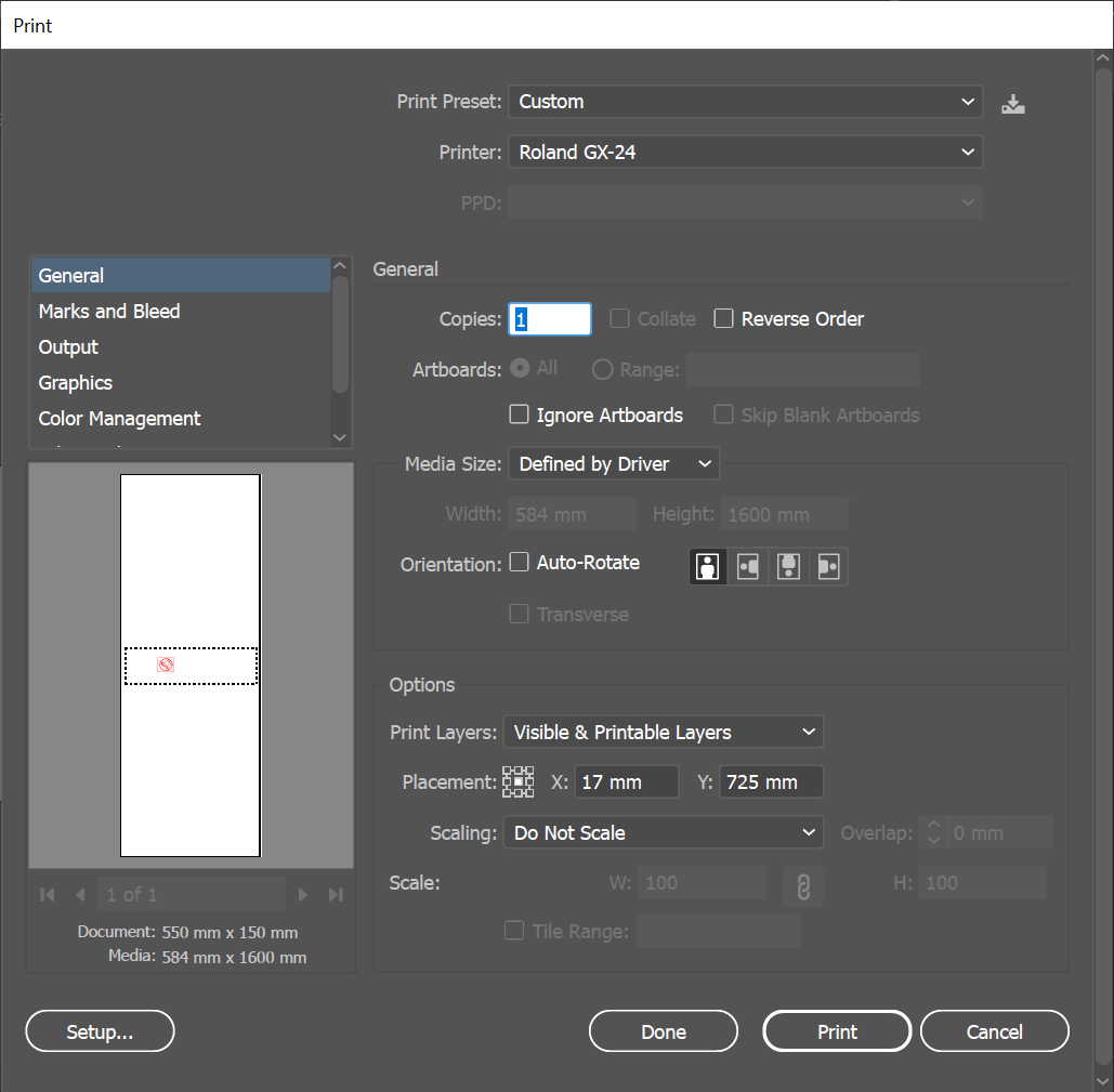
Next, you will bring up the print dialogue in Illustrator. You can use the layout settings to make sure that your vector design will be properly located on the canvas/material. The preview on the bottom left-hand corner is a useful guide to ensure proper cut out location and placement.
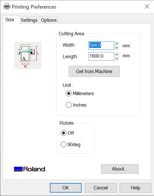
Finally, you will need to go to the Roland GX-24 print driver settings, and make sure that the material width is set correctly. This is the number that we received from the machine in the previous section. Once you set this up, you should be all set to print and send the job to the machine.
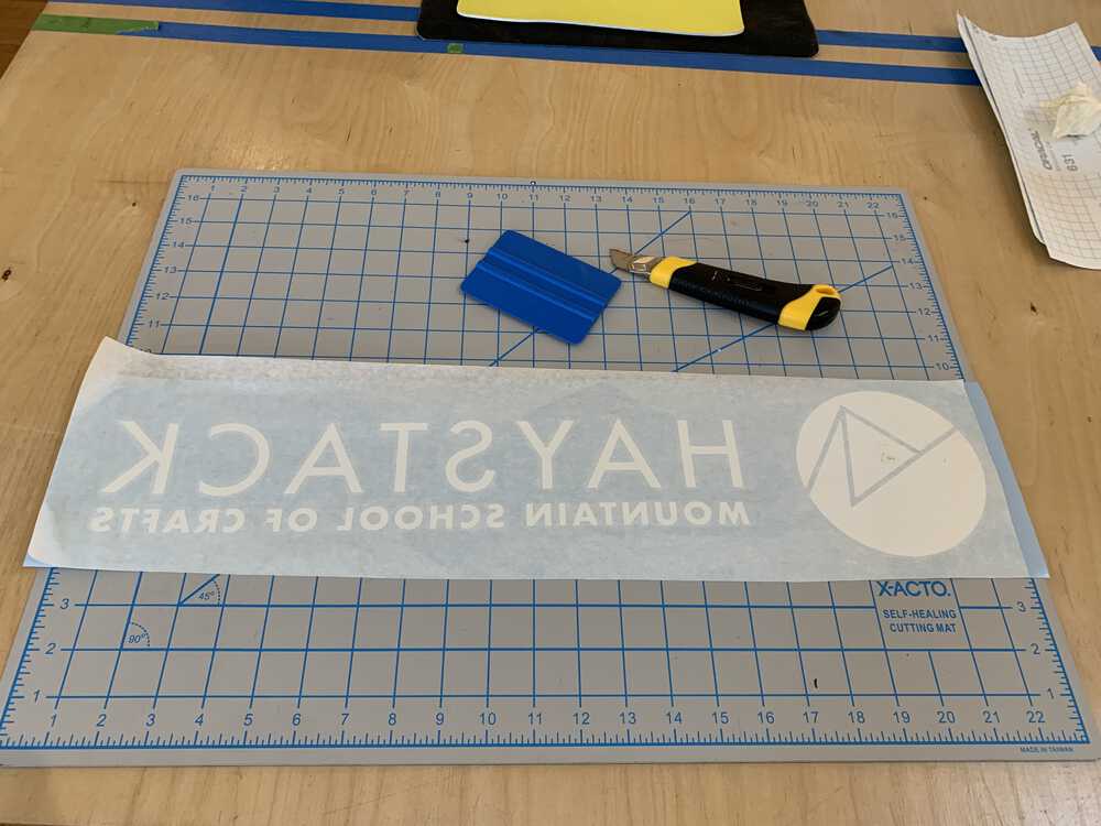
I already had the settings dialed in on the machine and some fresh blades on hand, so the cutting went smoothly on my first attempt.
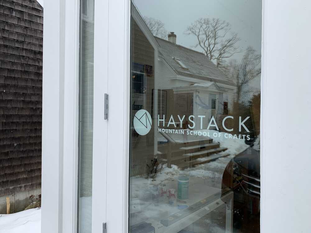
I installed our new vinyl signage on the door leading into the Fab Lab. I may do another one that says, “Fab Lab” but I want to think about the design a bit more than I had time for this week’s assignment.
Design Files
Haystack Glass Door Vinyl Sign