8. Computer-Controlled Machining
ShopBot Alpha 96
More to come on our machine here, it has been too cold to work out at campus, which is where our ShopBot is located…
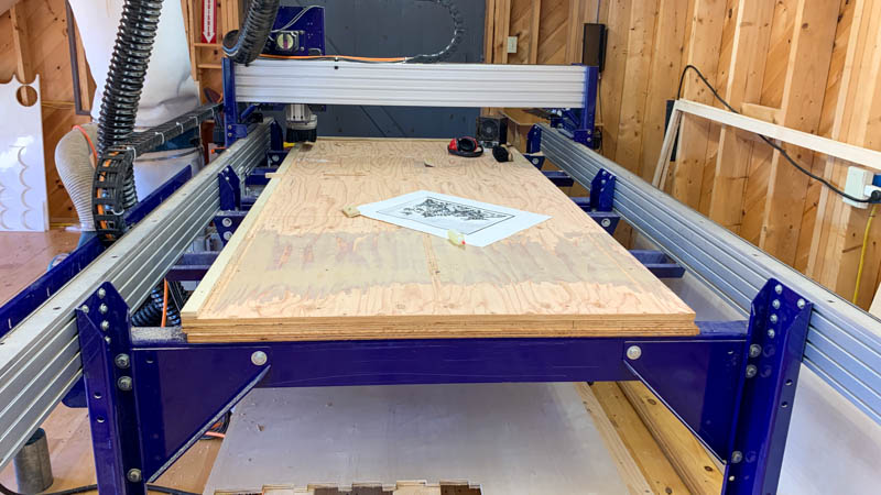
Monday, March 22 - 50 degrees here in Deer Isle so I took the opportunity to get setup out at our seasonal Fab Lab. I had OSB and Plywood delivered to the lab, figuring I would make my first project in the OSB and then switch to plywood for my final project.
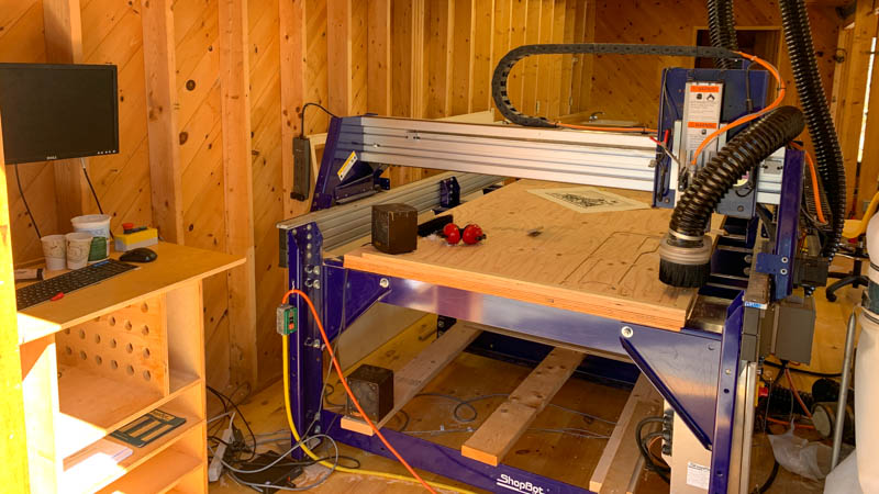
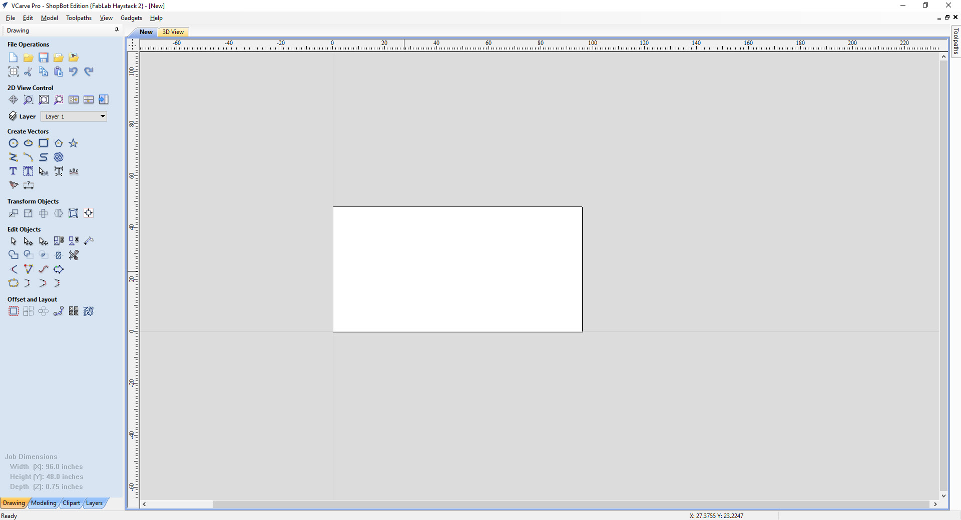
We relocated our ShopBot last summer to a new spot in our lab, and so not everything is completely setup with the machine. I got a new computer setup, which should run a bit faster than the previous 10-year old PC. We use V-Carve Pro to do all of our toolpathing and gcode generation.
Workflow & Testing
Before fabricating the standing desk, I wanted to do a test for both the material milling settings as well as the press-fit tolerance for the joinery. The OSB that I sourced claims to be 0.635, but I know better than to trust what the label on the product says. Wood is notoriously finicky when it comes to thickness, so it is always a good idea to run a tolerance test to make sure all the parts will fit together smoothly.
Design & Export
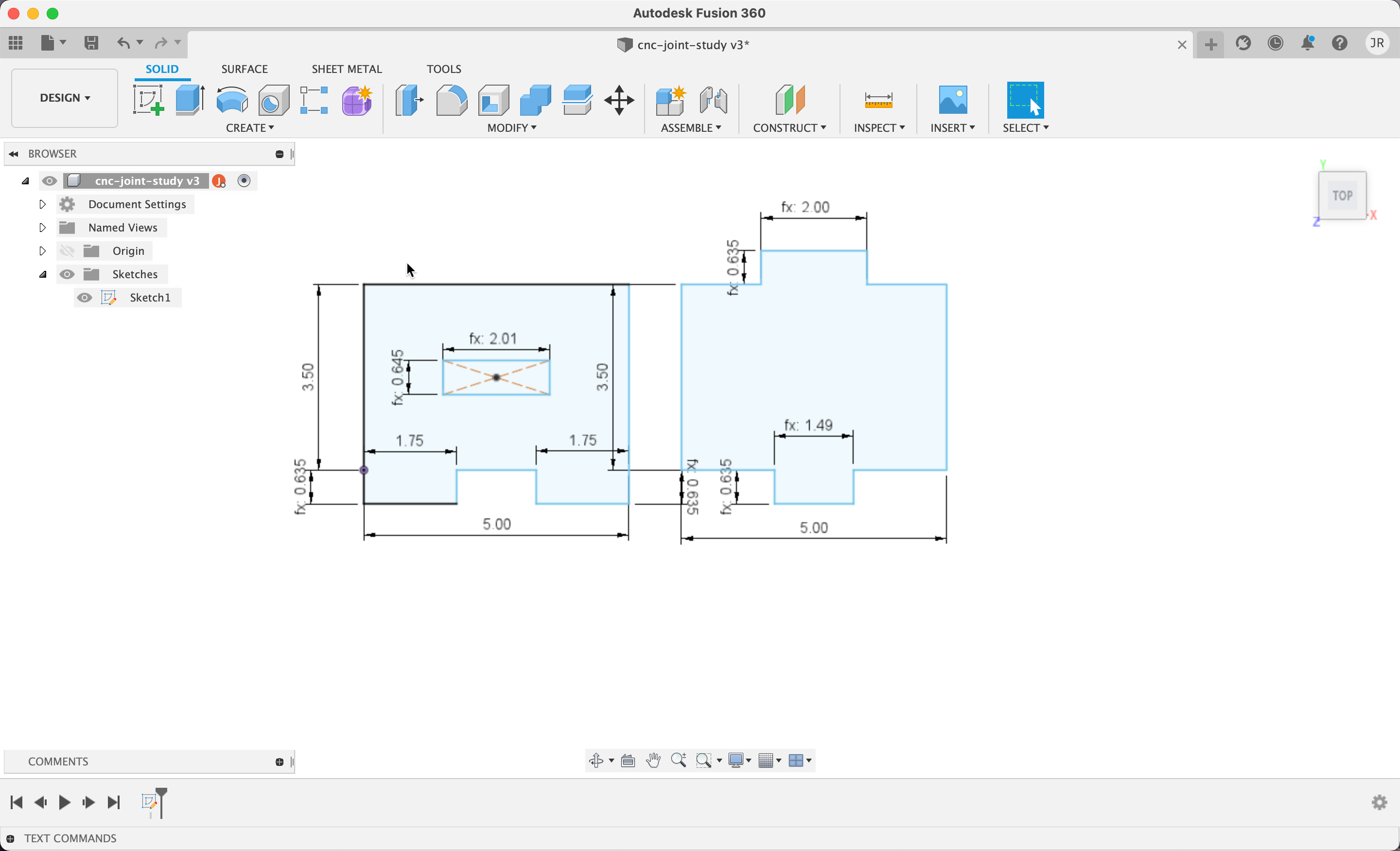
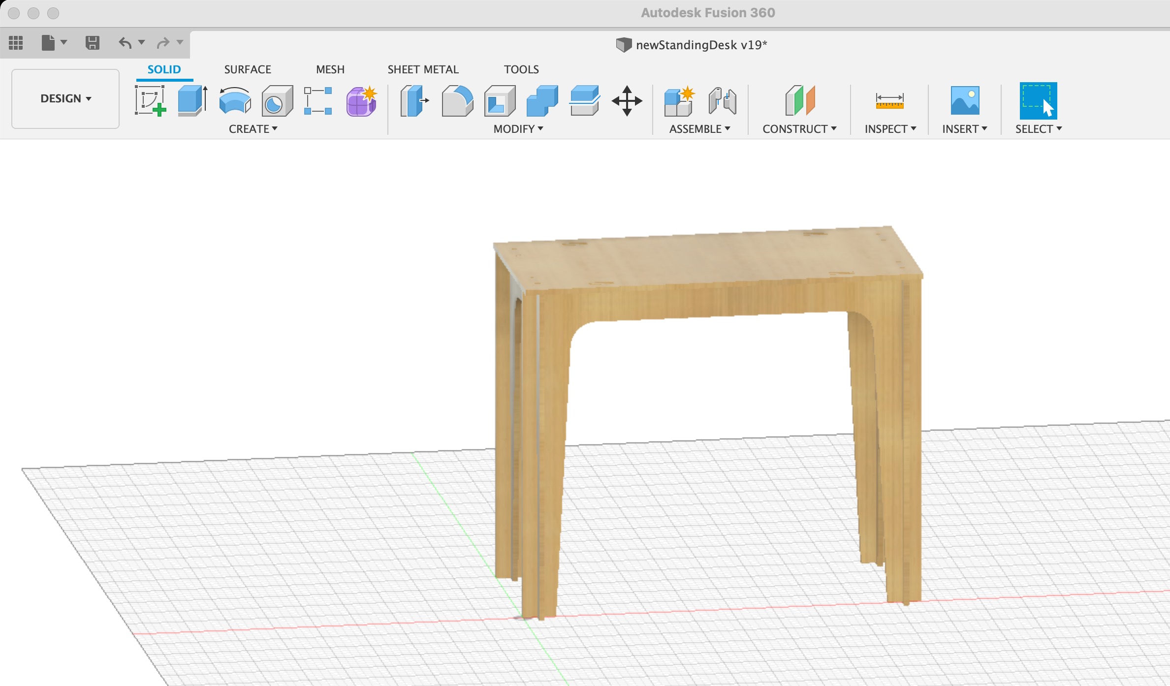
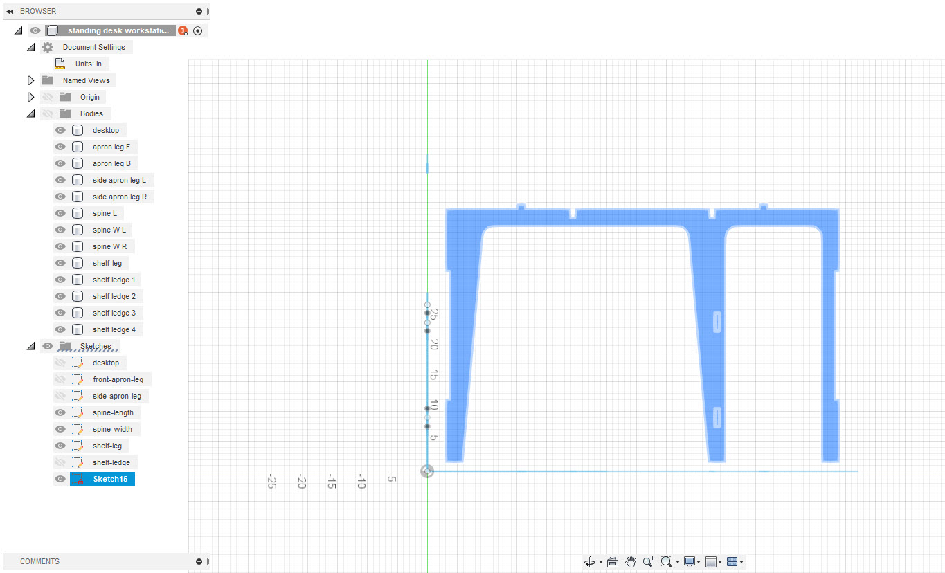
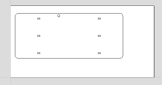
I designed a basic set of parts that would fit together a couple of different ways to try out different assemblies and joint configurations. Once a part is designed in Fusion 360, called a Sketch, it can be exported out as a DXF file format which will then get imported into V Carve Pro for toolpathing.
Loading Material
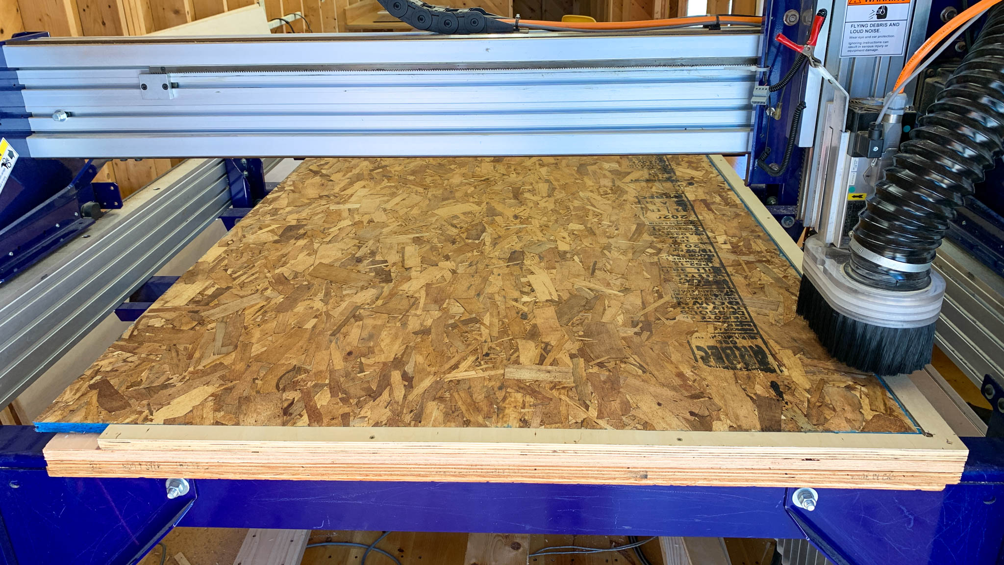
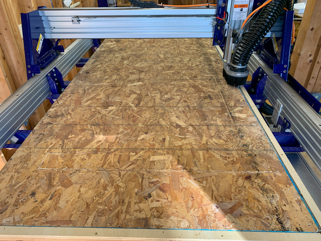
Our bed is setup with a MDF + MDO Plywood spoilboard with a straight edge that creates a frame to square the sheet material up with the machine. This makes setting the XY home easy using the ShopBot’s auto-home script routine. The photo above shows the OSB loaded onto the machine, reading for cutting.
Material Holddown
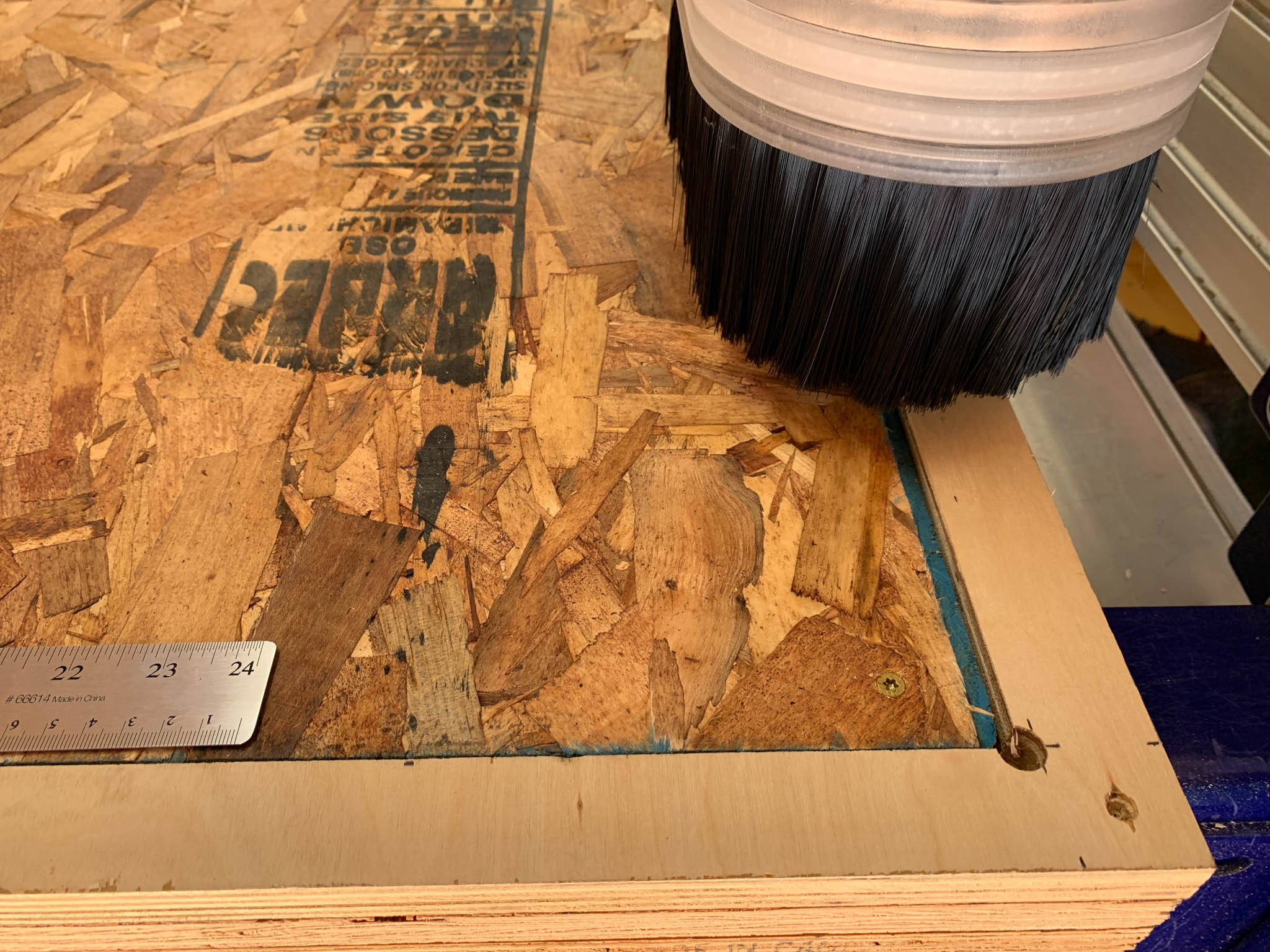
The material is secured, or held-down, to the spoilboard using self-tapping wood screws. These are easy and quick to install using an impact driver. The photo above shows a close up image of the material sitting flush with the XY table frame, near the home position.
Loading Endmill Tool
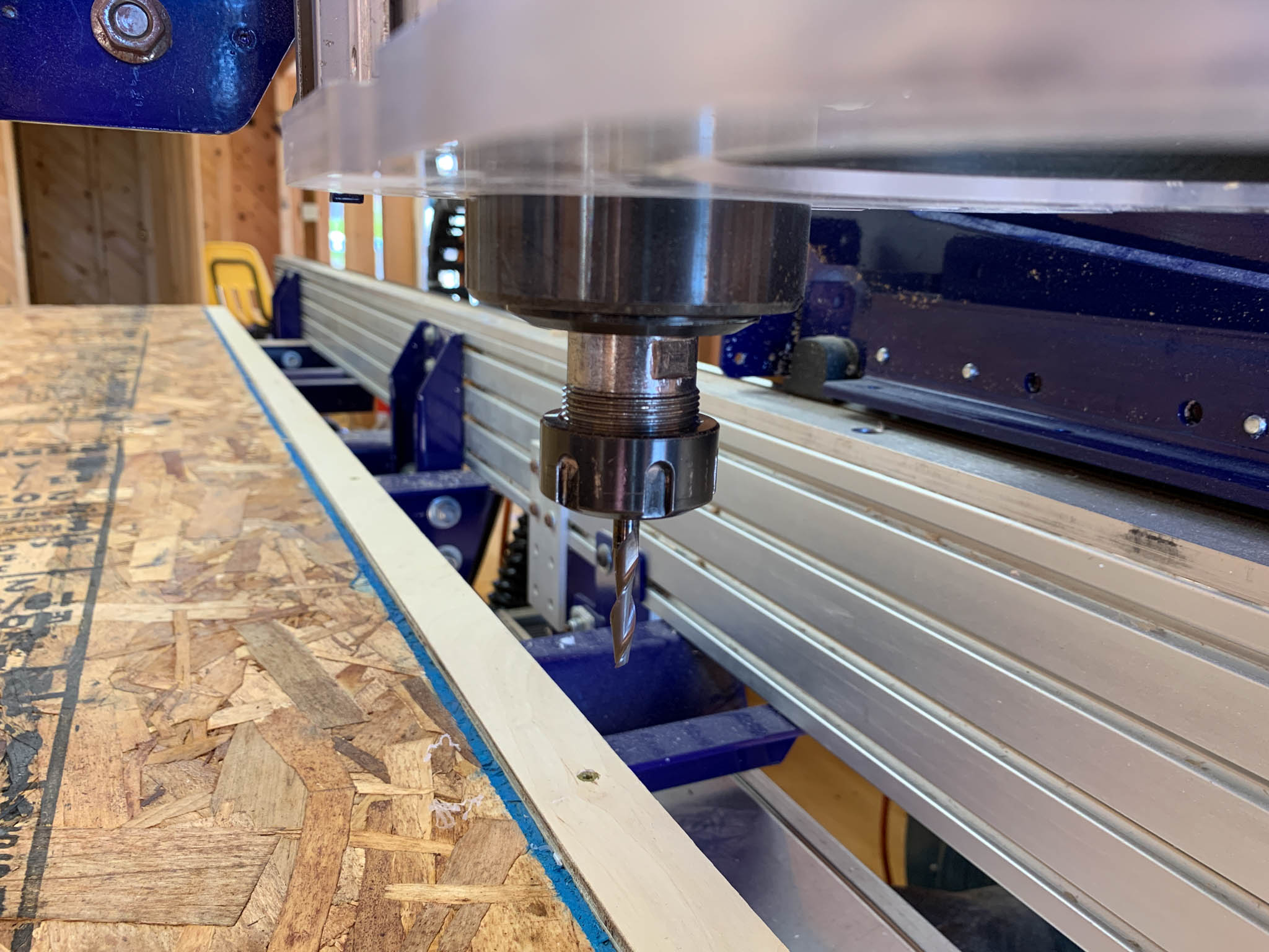
I decided to use a 1/4” downcut 2-flute endmill for the cutting of my parts. This is a fairly common tool for a lot of our applications, it can cut fairly fast without breaking but also has a small enough kerf to produce adequate detail. The install is loaded with an ER25 collet, which is install into the spindle’s collar. The photo above shows a close-up of the tool installed on our machine. After the tool is installed the XY is homed using the homing routine built into ShopBot’s software, and then the Z-axis is homed using the metal plate and another routine. This Z-home routine uses a conductive sensor to complete a circuit when the tool makes contact with a metal plate sitting on the surface of the material. This allows the machine to automatically set the Z-axis home without having fuss too much with the machine.
Cutting Parts
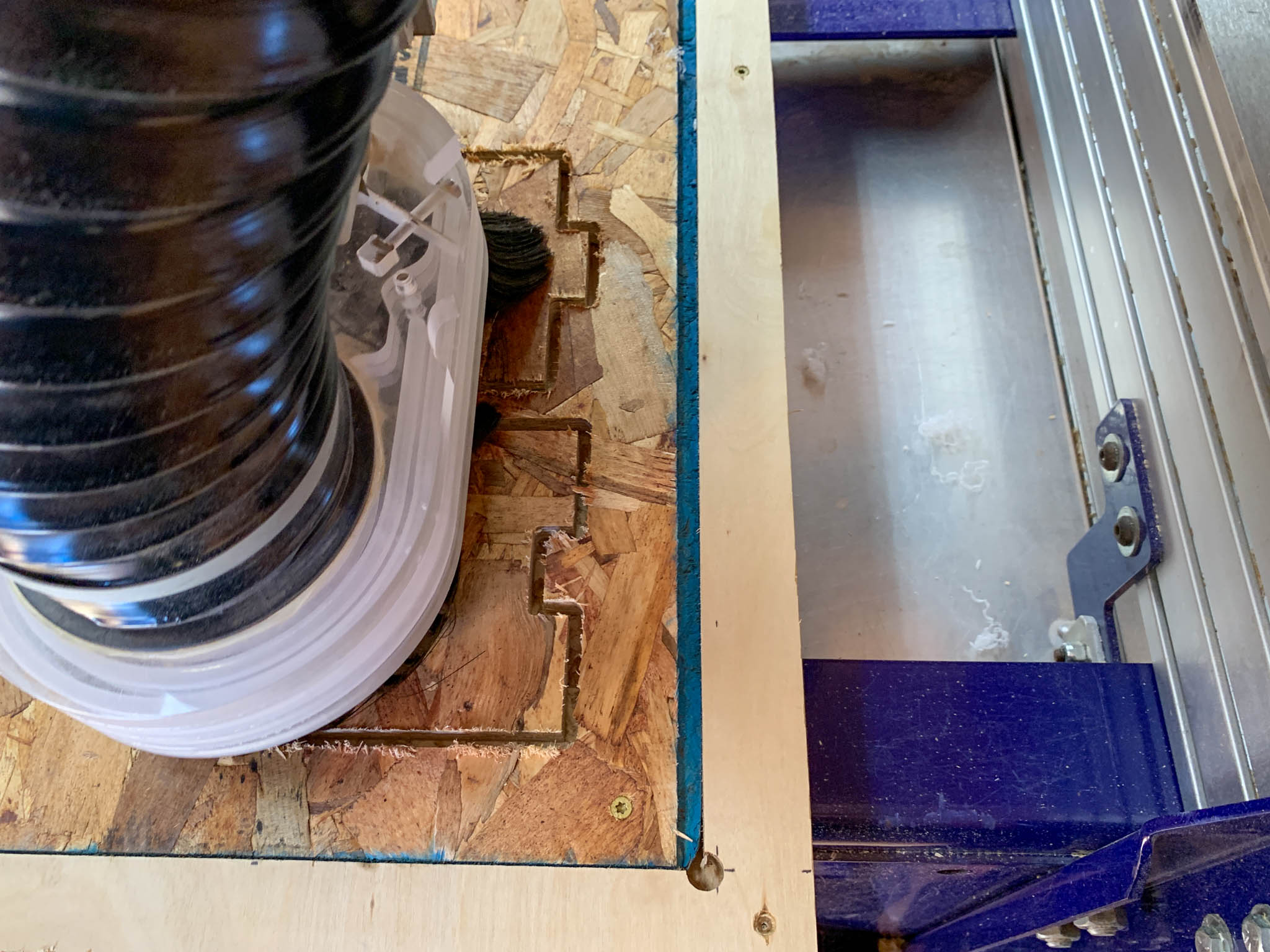
Okay, onto the cutting. V-Carve Pro outputs a Gcode file specific to ShopBot machines, not surprisingly referred to as an SBP file. This gets loaded into the ShopBot Control software and then it is off to the races. The most important thing is to make sure you have turned on the machine’s spindle. The machine will run without spinning the tool if you do not do this and will 100% break your tool upon contact with the material. Turn on the Spindle and run the file.
Finished Parts
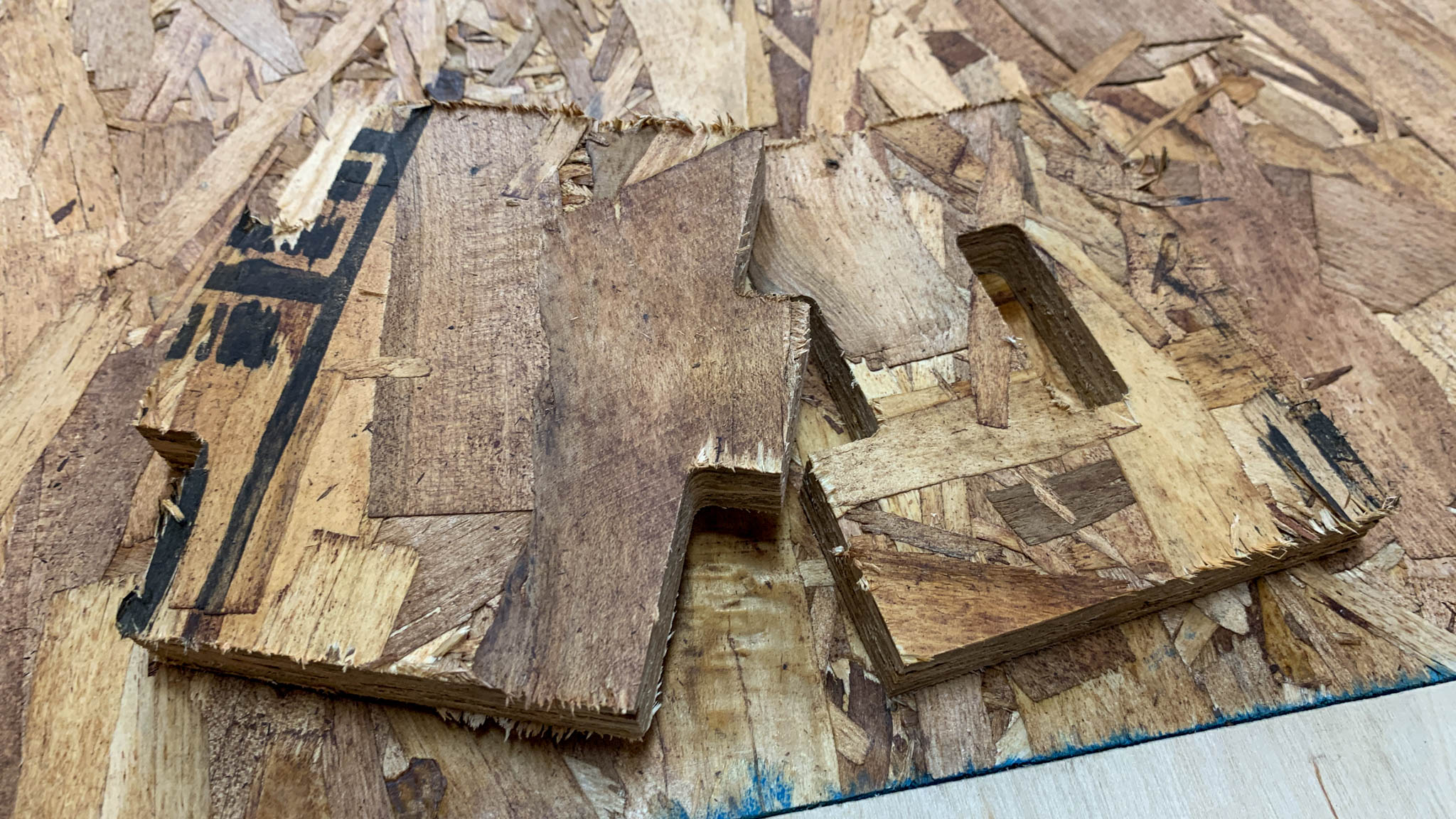
The parts cut out in about two minutes, but there will be some sanding needed to clean up the bottom edge of the parts. This is common when using a downcut tool to cut parts out. That is okay, this is a test and I will plan accordingly for the standing desk.
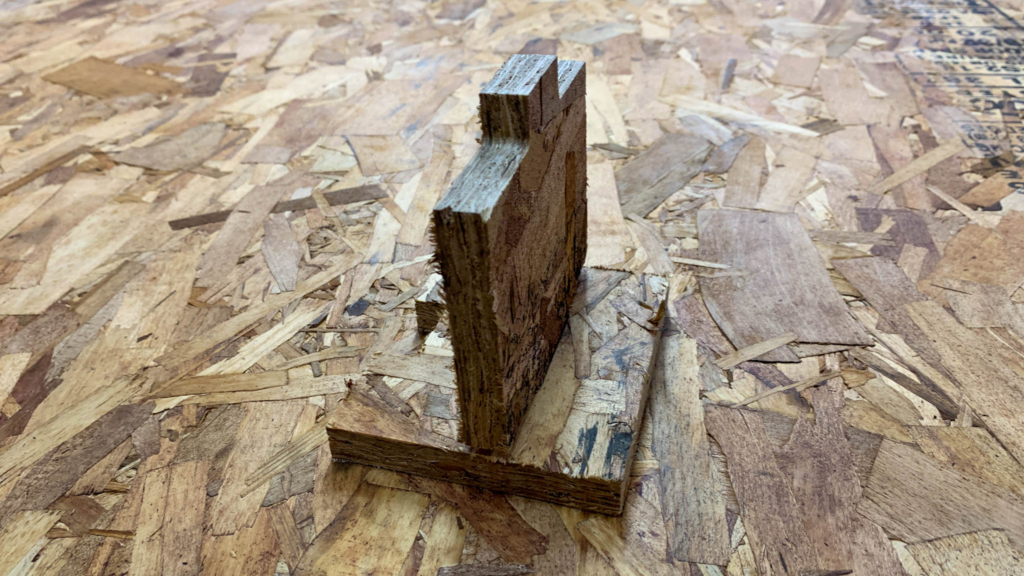
To my surprise, the test joints using my dimensions fit tight and just the way I was hoping. This usually never happens when I design press-fit joinery on the CNC machine, so I must be getting better at this. Anyways, onto the standing desk.
Standing Desk Design
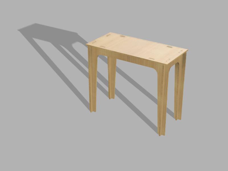
For my “make something big” project, I decided to make a standing height workbench-desk for my home lab. I was inspired by David Yamnitsky’s Standing Desk and my design borrows from his as well as some other inspiration from atFab.
Exporting out of Fusion 360 and Importing into VCarve Pro
CNC CAM Toolpaths with V-Carve
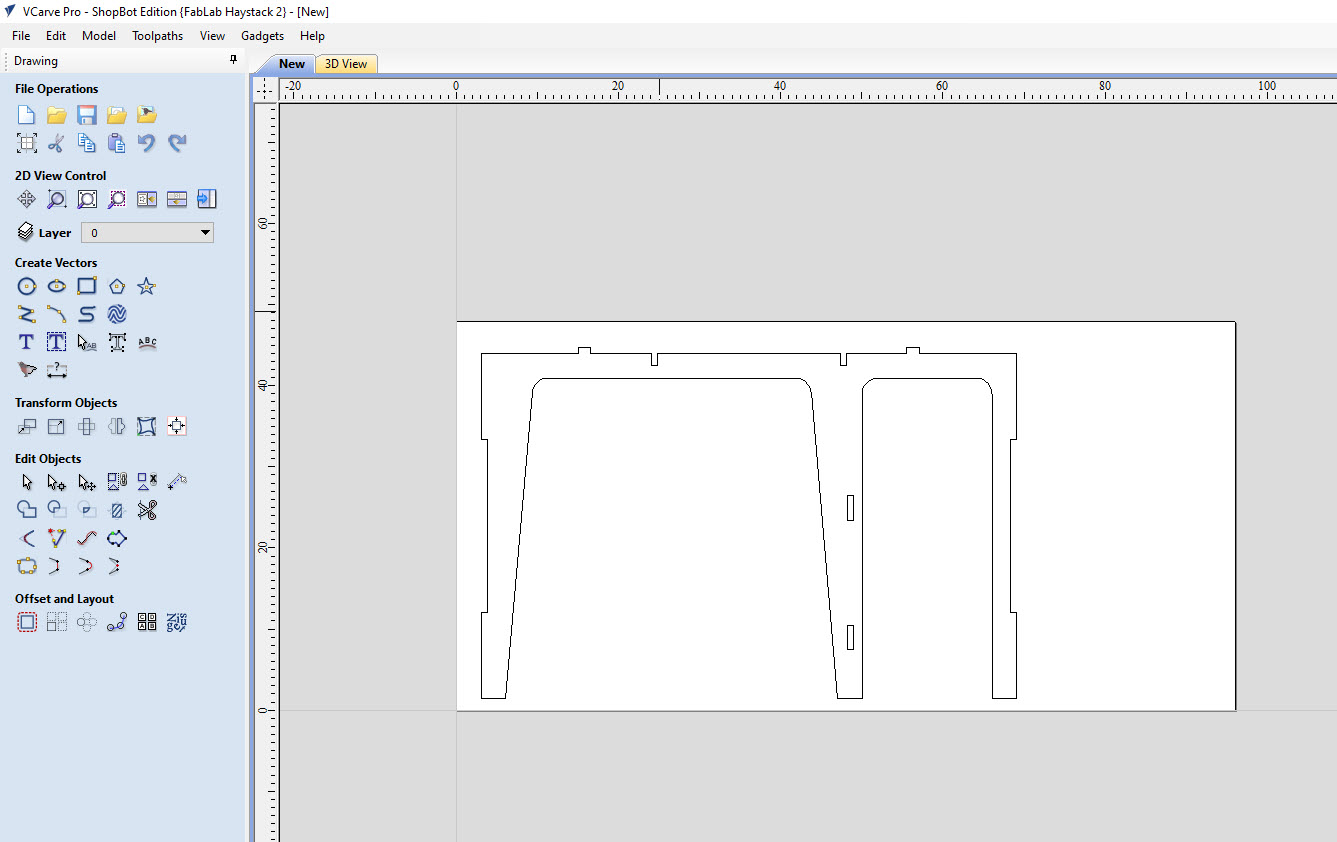
To convert Fusion drawings, or any CAD drawings, into machine instructions, a CAM (computer-assisted machining) program is used to create toolpaths. Toolpaths are instructions for the machine that specify how deep to cut, how fast to cut, where to cut, and so on. Creating toolpaths requires specific knowledge of the material, tool, and design that you are trying to cut. There are more considerations during this step in the project.
Profile
For my project, I kept the toolpath process simple and created Profile Toolpaths which instructs the machine to follow the drawing with the tool, cutting along the line. This is similar to what the laser cutter or vinyl cutter does with an outline or vector drawing. Below are the settings and a description of my approach to cutting this project.
- Tool: 1/4” Compression Endmill. This is the physical tool that is loaded into the machine. 1/4” diameter means 1/4” of material will be removed so you cannot place things closer than 1/4” together when laying out your sheet on the CAM software.
- Cut Depth: 0.25”. This is the maximum distance the tool will plunge and cut into the material at any given time. Since my material is 0.65” thick, the machine will take 3 seperate passes to cut out a part completely from the sheet material. You do not want to try and cut out your part all at once because it would put too much stress on the tool and break.
- Cut Rate (Feed Rate): 3.5 in/sec. This is the rate at which the machine will cut along the line, also known as the feed rate or cutting speed.
- Spindle Speed: 15000 RPM. This is the rate at which the tool will spin and cut through the material. Some materials, like plastic or metal, require low RPM when cutting to avoid overheating and melting in the case of plastic. With organic materials, such as plywood, you can cut at higher RPMs and get more cutting power from the tool, allowing you to cut at higher feed rates.
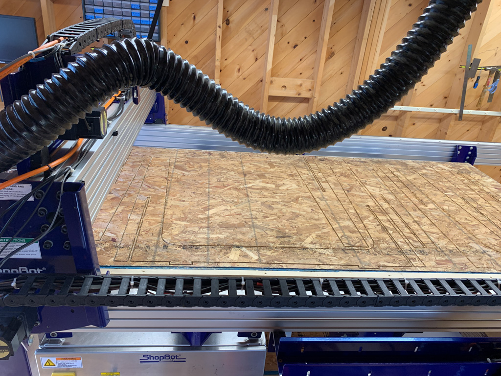
Milling
Material Hold-Down
To prepare for milling the project, I had to secure my material to the bed of the machine. Haystack’s ShopBot is setup with a 3/4” MDO surface that acts as a sacrificial layer. To keep things simple, I used self-tapping wood screws and screwed the material to the bed of the machine at all four corners.
The machine milling out the project, viewed from the side. The machine works quickly, cutting everything out in approximately 30 minutes.
After cutting the parts out, I had to do a lot of clean up and sanding. The OBS material that I was working with is pretty rough, and required a lot of sanding to get smooth and assemble.
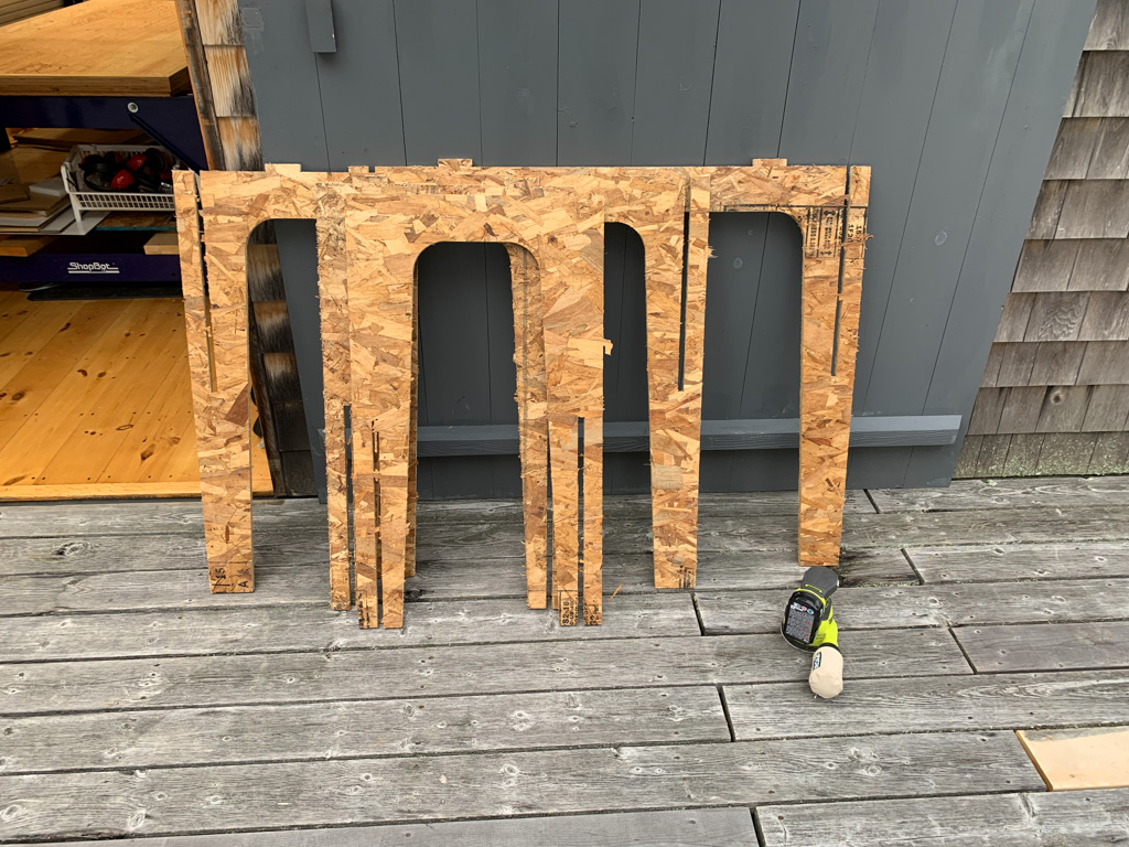
Once I cleaned everything up, I began assembling the legs.
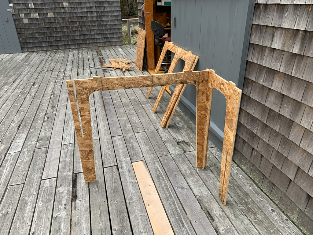
More legs going together. The joints were designed correctly and the fit was snug, exactly what I was hoping for. I did not need to sanding in between the joints to make the parts fit. I did use a rubber mallet to force everything together. No glue or other fasteners were required to do this.
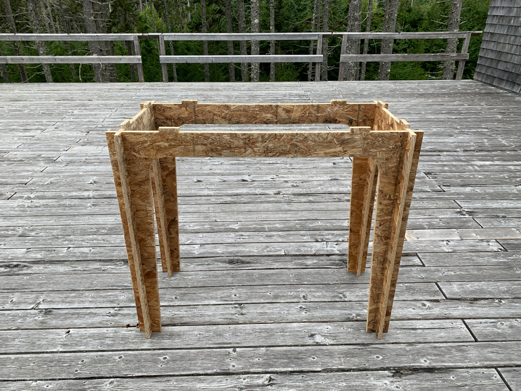
Getting everything ready for the final tabletop. This part required a lot of whacking with the rubber mallet. However, it eventually all fit in together perfectly. I was surprised that it would so well with the tolerance that I designed.
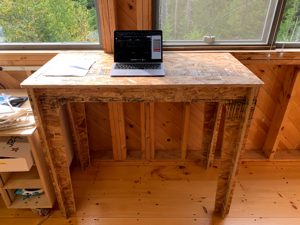
A look at the final assembly. Overall the project was simple to design and cut, I may eventually design something with nicer looking plywood and add some shelves or drawers. The height of the desk was designed to accomodate me, 5‘11”, so it works well as a standing workstation.
Files
- VCarve Pro CAM File
- Shopbot GCode (SBP): Sheet 1 Profile Cuts
- Shopbot GCode (SBP): Sheet 1 Scrap Cuts
- Shopbot GCode (SBP): Sheet 2 Profile Cuts
- Shopbot GCode (SBP): Sheet 2 Scrap Cut