11. Input Devices
This week I worked with an input temperature and humidity sensor, designing a custom board for the sensor, and reading its values. (Apr 07)
11-13 minutes
Sensor Board Design
Due to the use of multiple-input sensors in my final project Aquaponics Tank, I based my work this week around creating a sensor that could eventually be used in my project. Originally, I planned to experiment with measuring PH via a ph sensor we had in our lab, unfortunately, however, this sensor was old and unoperational, so I decided to create a temperature and humidity monitoring board that would be needed inside my tank instead.
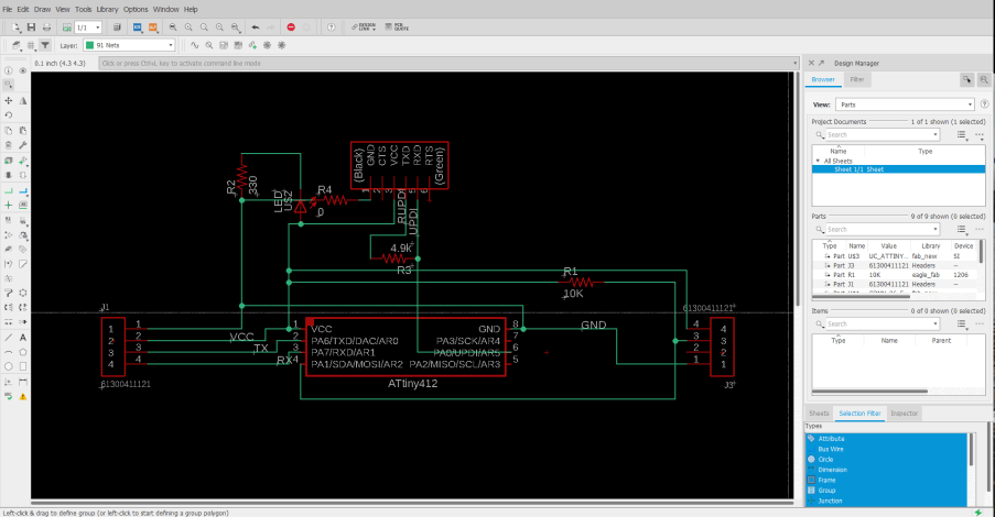
I began this process by reading up on the DHT11 temp and humidity sensor, finding this link on its set up with an Arduino helpful, giving me some useful wiring diagrams. I planned on using this DHT11 Temperature and Humidity sensor on my temp and humidity monitoring board, reading the sensor through an onboard ATtiny 412, and writing the read values to another microcontroller through RX and TX pins. I started in EAGLE, creating a small ATtiny 412 circuit, incorporating a DHT11 Temperature and Humidity sensor, as well as some headers for programming and communication. First, I started a new schematic for the board, keeping in mind the required components while adding them to the schematic. The DHT11 sensor is a four-pin sensor with a VCC, GND, and two data pins. In my case, I communicated with the sensor via one data pin, keeping in mind this pin not only needed to be connected to my ATtiny 412 but also ran to VCC with a 10k ohms resistor. Along with its connection to this sensor, my board’s ATtiny 412 also runs to two separate headers, one for programming via the board’s UPDI pin, and another supplying the board’s power, and RX and TX pins, for future communication between boards. A final little touch to this schematic was a power indicating LED, and this left me with the schematic shown below.
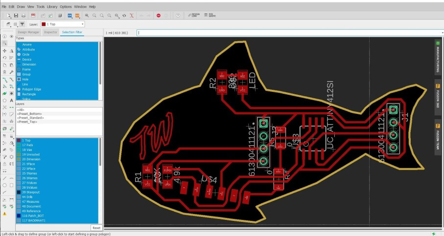
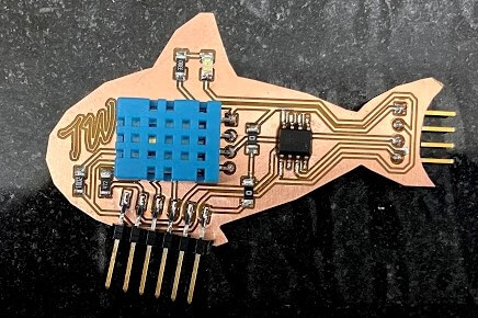
The next step in this board design process was the conversion of my schematic into my temperature and humidity reading board. Keeping with the aquarium theme, I decided to shape this board like a fish, following the same steps I used creating a custom board shape in eagle during week 6. For this board outline, I used the same fish icon I had created in that week’s assignment, importing the shape into the dimensions layer of my sensor board file to create the shape. From here I began the process of laying out the board’s components, in eagle, starting with the mounting position of the DHT11 sensor and ATtiny 412, and positioning around those two components. One thing I had to keep in mind during this layout is the size of the DHT11, as its connection to my board using a 4 pin header, but the body of the sensor itself was much larger than this. I began by positioning the header where I thought the rest of the sensor would fit, and checked this positioning by drawing a square from the corner of the header, so its dimensions were the size of the DHT11. From here I laid out all other components on my board and routed the board’s traces. Due to the small size of this board, the trace routing was a relatively simple task and left me with a nice-looking temperature and humidity monitoring fish board.
Milling and Soldering
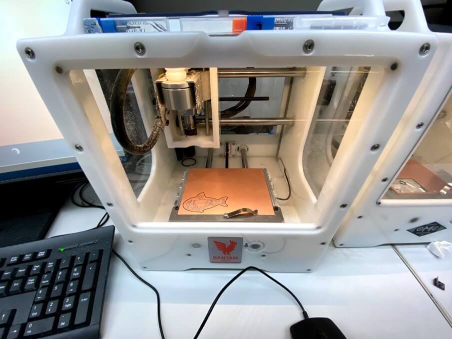
With my board’s design work complete, I began the manufacturing process, starting by milling the board. Here I followed the same steps I used while milling boards previously in week 4. I imported my sensor board file into our PCB mills software, went through the machine setup process talked about in week 4, selected the Traces operation, and ran it with a PCB engraving bit. These traces were run with a .27mm trace clearance value, as it was the largest value I could run without ramping up the time,
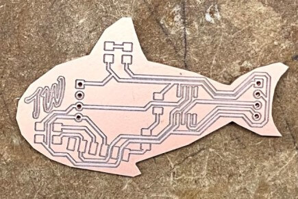
Upon the completion of this trace operation, I next ran the boards holes and outline, by selecting the corresponding operations in the software, and running them with a 1/32” bit. These two operations left me with my milled fish board, ready to stuff and solder.
The soldering process of my fish sensor board was relatively straightforward due to the board’s limited components. I started off soldering this board’s smaller components and microcontroller before moving onto the DHT11 sensor. The practices I followed during this process were the same that I picked up while soldering in my week 4 assignment. However, on the soldering of this board, I began to move away from using solder flux on all of my board’s components. I found that when soldering small surface mount components the flux is a little unnecessary, and leaves an undesirable sticky residue. After this board soldering, I plan on only using solder flux for larger board components like the microcontroller, and therefore reduce any excess sticky residue on my boards.
Programming
Similarly to before starting my board’s schematic, before programming the board, I read up on the DHT11 sensor, referencing the same site as before, found here.
“The DHT11 detects water vapor by measuring the electrical resistance between two electrodes. The humidity sensing component is a moisture-holding substrate with electrodes applied to the surface. When water vapor is absorbed by the substrate, ions are released by the substrate which increases the conductivity between the electrodes. The change in resistance between the two electrodes is proportional to the relative humidity. Higher relative humidity decreases the resistance between the electrodes, while lower relative humidity increases the resistance between the electrodes. The DHT11 measures temperature with a surface mounted NTC temperature sensor (thermistor) built into the unit.” (Circuit Basics)
The sensor relies on the DHTLib Arduino library and can read the sensors data pin into a readable humidity and temperature output. The libraries follow the equation below to derive the relative humidity from the sensor.

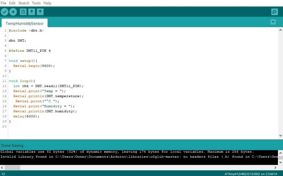
With knowledge of the DHT11’s workings, I began programming the code to read temp and humidity through the DHT11 and print the found values through TX to a serial monitor. I used the sensors reference code found on the Circuit Basics code as a reference and began the coding process. The code starts by including the needed DHTLib library and setting up the DHT11’s connections to my boards ATtiny 412. Next, the code begins serial and then prints the found values to it, with the prefixes “Temp” & “Humidity” in front of their corresponding values. This left me with the sensor reading code below.
#include <Arduino.h>
#include <dht.h>

dht DHT;

#define DHT11_PIN 4

void setup(){
  Serial.begin(9600);
}

void loop(){
  int chk = DHT.read11(DHT11_PIN);
  Serial.print("Temp = ");
  Serial.println(DHT.temperature);
  Serial.print("Humidity = ");
  Serial.println(DHT.humidity);
  delay(5000);
}
At the end of this sensor reading loop, I included a 5-second delay, as the DHT11 can only be read every 2 seconds, so this gives the sensor plenty of wiggle room.
With this code flattened out, I wired my fish sensor board to my in-circuit programmed, made in week 4’s electronic production class, connecting my boards GND and VCC to the programmers corresponding pins, and my sensor boards UPDI to the UPDI pin of my in-circuit programmer. I followed the same programing steps I’ve used for all of my other ATtiny 412 containing boards, like that in week 4, uploading my sensor reading code through my in-circuit programmer using the Arduino IDE’s Upload Using Programmer tool. This code was uploaded successfully to my board, and I was ready to move on to testing and reading my sensor.
Testing & Sensor Reading
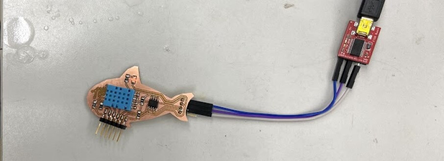
With the programming for my fish board done and code uploaded to the board, I was ready to move onto the reading on my sensor via serial. This fish board is designed to be used in the future to monitor the temperature and humidity inside of my final project aquaponics fish tank. I plan on communicating between this board and my future fishtanks mainboard via serial, and while testing this board, I attempted to mimic this as best as possible by reading the fish board’s sensor through its transmitting TX pin. To begin to read my DHT11 sensor, I wired my fish sensor board to an FTDI chip to allow connection to my computer. I attached the VCC and GND headers from my board’s data out headers to their corresponding pins on the FTDI chip, as well as my fish boards transmitting TX to the FTDI chips receiving RX pin, like shown in the picture below.
From here I was ready to attempt to read my board’s DHT11 through serial, and through the FTDI chips port in the Arduino IDE, I opened a serial monitor to read the output being transmitted from my sensor board. Unfortunately, upon viewing the serial monitor, the window only read -999 as a value for both temperature and humidity, clearly not the right values for the room I was in.
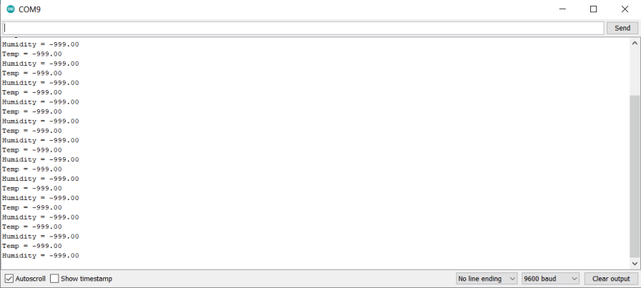
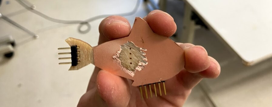
After a bit of error research on this -999 value, I found it was the error code given by the DHT11 when there is a sensor error, leading me to believe my board was shorting at some point. However, after troubleshooting this for a while under a microscope, I found no bridges or cold joints on the top of the board. During this time, however, while I was showing my board to a former Fab Academy graduate, Elaine Liu, she brought up the fact that my board was milled on a double-sided PCB blank, a question I didn’t think would be an issue, until I realized I was using through-hole headers for both my data out headers, and DHT11 connection, and that all of these pins were shorting on the copper back of the board. This mistake of milling on a dual-sided PCB black was pretty easy to resolve, first by removing the through-hole pins, and then using a Dremel to sand down the copper around the through-hole pins, before resoldering them. This removed copper back is shown in the image below.
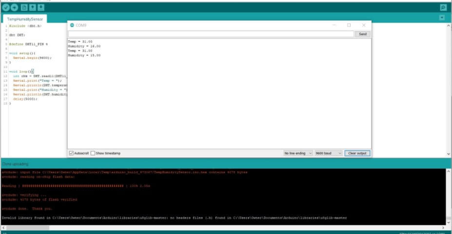
I reattached this resoldered board to my FDTI chip, using the same pins to connect the two as before, and then attempted to read the sensors values again, and this time, it worked! Every five seconds the serial monitor is updated with reading temperature and humidity values from my DHT11, and output the values in a serial monitor through serial, shown below.
Group Work
This week’s group assignment was to probe an analog and digital input device using an oscilloscope. I worked with one of my classmates, Graham Smith to probe both an analog potentiometer and digital button input. Click here to view our group documentation site, with this week’s assignment on it.
Downloads
- Click Here to access and download all of my files from this week