Computer-Controlled Cutting
In this week, we got further acquianted with the modeling software of our choice (FreeCAD in my case), and got introduced to two cutting devices in the lab: the Roland GX-24 vinyl cutter and Epilog Mini/Helix -- Model 8000 laser cutter.
The group assignment for this week is available at the group website.
In a nutshell, the most time was spent figuring out how to not run into problems in FreeCAD and the rest of the time was spent on reading the manuals of the cutters and actually working with the machines.
One software that I left untried was Deepnest in order to pack cuttable pieces in an efficient way and merge common lines to avoid waste of material, time, and also warping the pieces from too many laser passes. This was partially accomplished though using CorelDraw, which proved rather pleasant to work with.
Designing the construction kit
For this week we had to design, lasercut, and document a parametric construction kit, accounting for the lasercutter kerf, which could be assembled in multiple ways. I decided to do the design using FreeCAD. As mentioned before, FreeCAD presented many problems to use. I tried to design the simple parametric pieces a few different ways before succeeding. Among the failed attempts were trying to design the whole part as a sketch with parametric fitting sections, and then padding that, but FreeCAD refused to pad that. Another attempt was to sketch half of the 1/n-th piece of an n-cornered shape, then pad that, mirror that, and then try to polar array it, but FreeCAD would refuse to array a mirrored object. Last attempt was to sketch the entire 1/n-th of the n-cornered shape, and then pad that and polar array that, which worked. Complete parameterization of this design was done such that by only entering the number of corners of the object, the shape would automatically be generated all the way to the end.
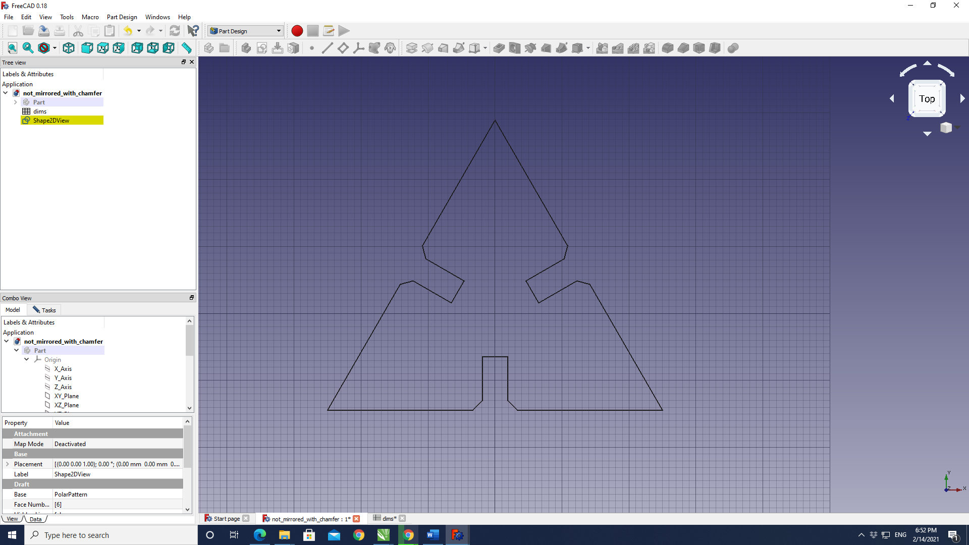
Here's a view of the sketch of 1/3 of a triangle as a starting point. Every one of the dimensions of the shape are defined by a variable (parameter). This shape would automatically change to e.g. a square if simply the number of corners were changed to 4 on the spreadsheet page:

Below the output of the design is shown as the number of corners of the shape is specified as 3:
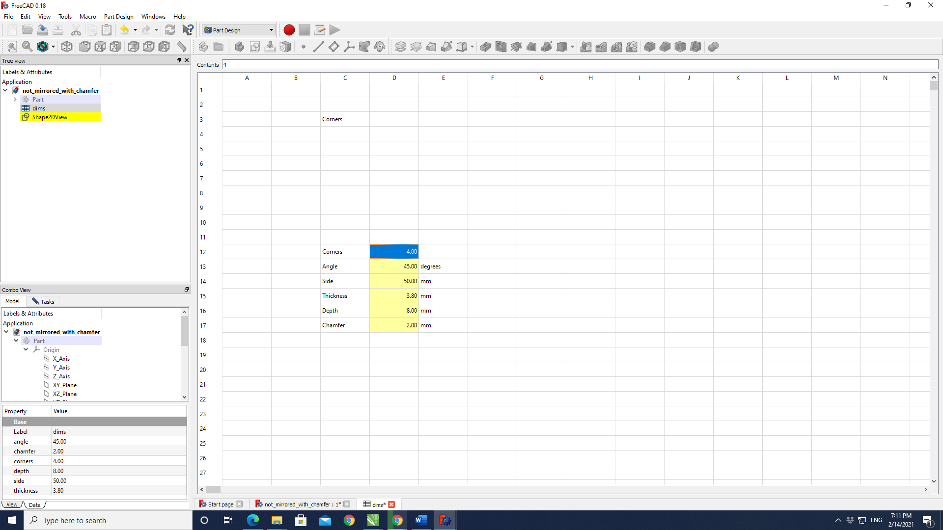
Here the parametric spreadsheet can be seen:
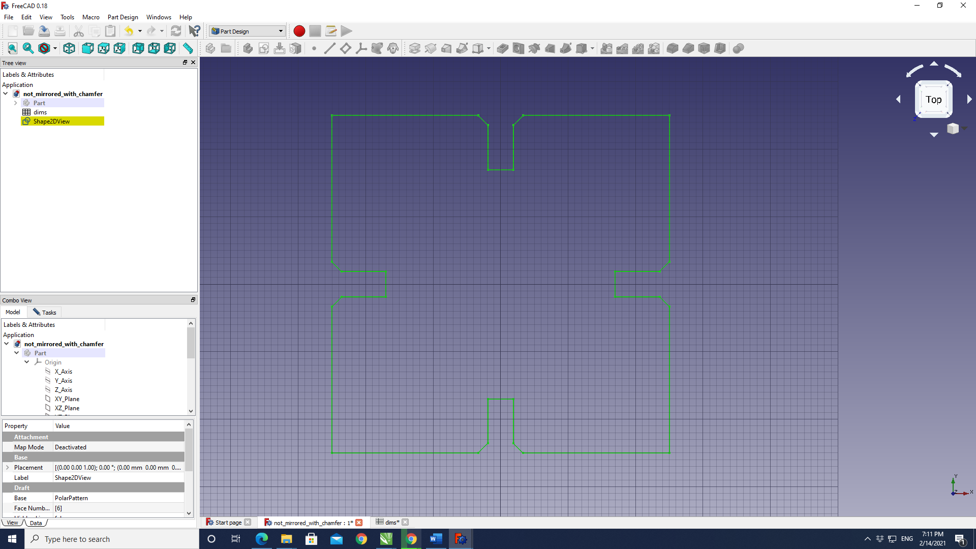
And here the number of corners have been changed to 4:
As the design was completely parametric, with the shape calculating the corresponding angles with the number of corners taken as input, changing the shape was a matter of alternating the number of corners. The number of corners as high up as 20 were tried, and the design responded immediately by generating the appropriate shape.
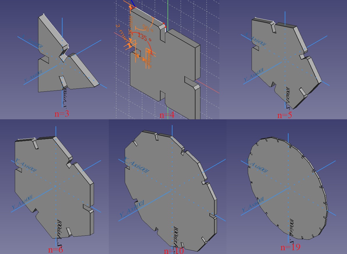
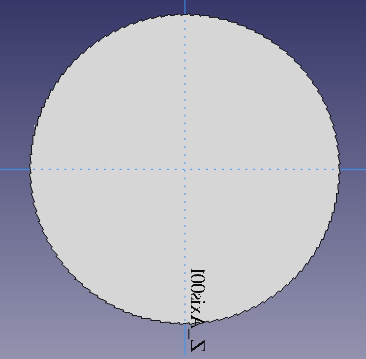
The design was also pushed to its limits by specifying the number of corners as a 100, or attempting to generate a hectogon. This did slow down the program a bit, but eventually a hectogon was generated, albeit without the dips to insert other pieces:
The laser cutter
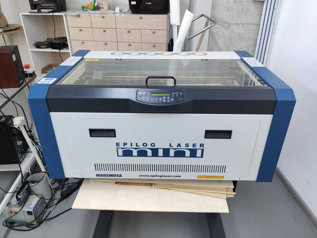
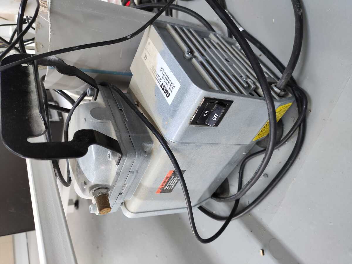
An Epilog Mini/Helix Model 8000 is used at the Fab Lab Dilijan:
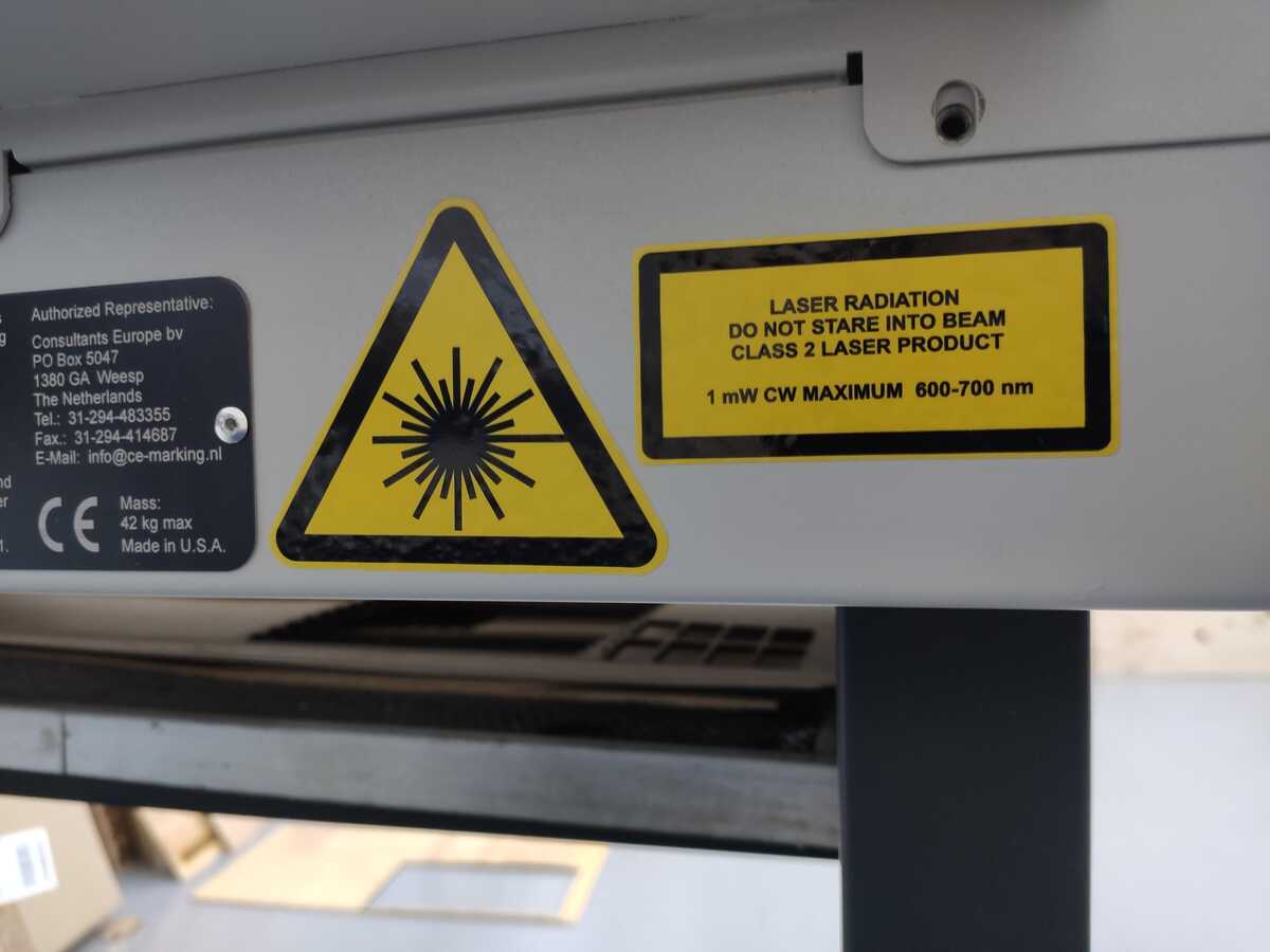
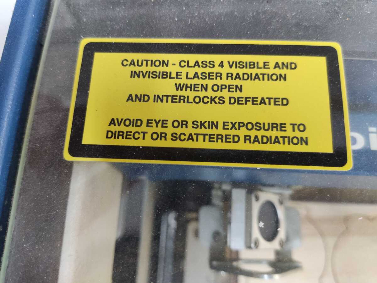
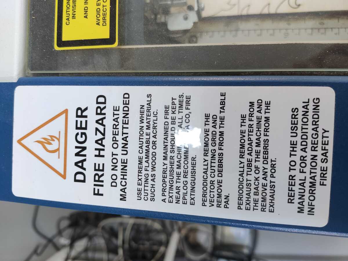
Before using the laser, we were instructed to read the manual and especially familiarize ourselved with the safety instructions therein. The Epilog Mini/Helix Model 8000 laser is a class 3R laser product that uses a high-power CO2 laser. The laser beam is fully contained inside a cabinet that is turned off if the door is opened, which means no special precautions are required to operate it safely. However, the visible output beam of the pointer is accessible to the operator, which is similar to the laser pen-pointers, and can be potentially hazardous if directed to the eye.
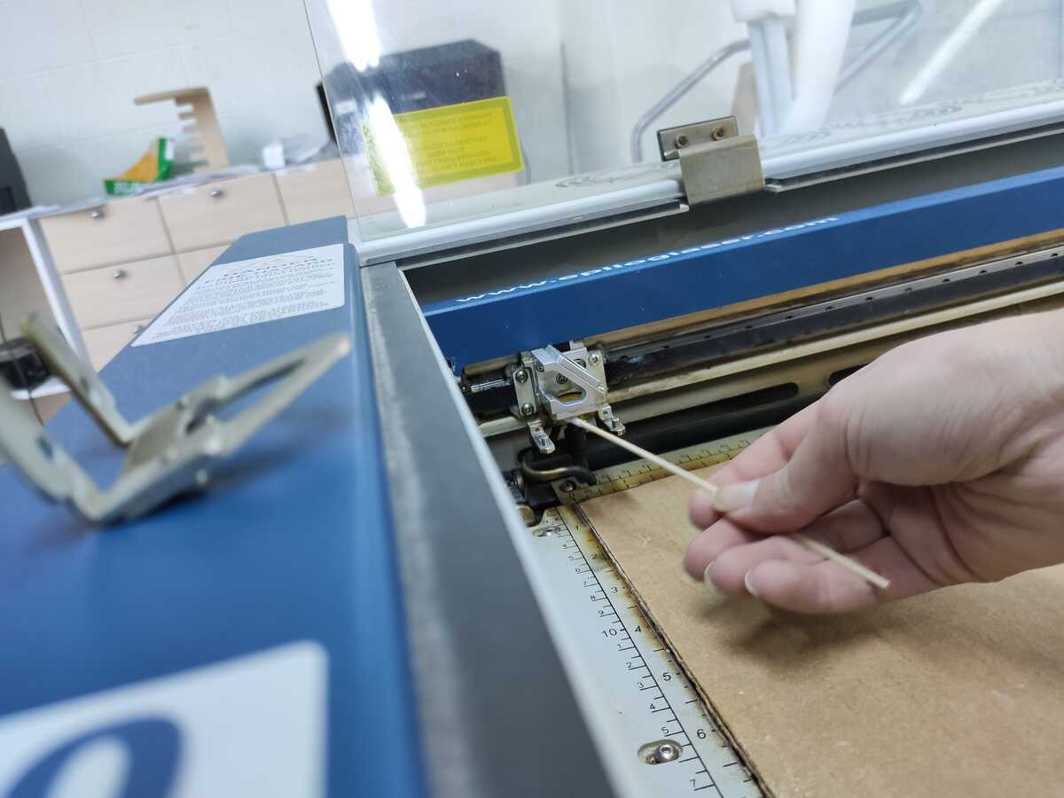
Part of setting up the laser for use includes cleaning the lense, which is accomplished be using a special liquid and applying it with a long swab and also wiping the lense (on both sides) using a lense cleaning wipe:
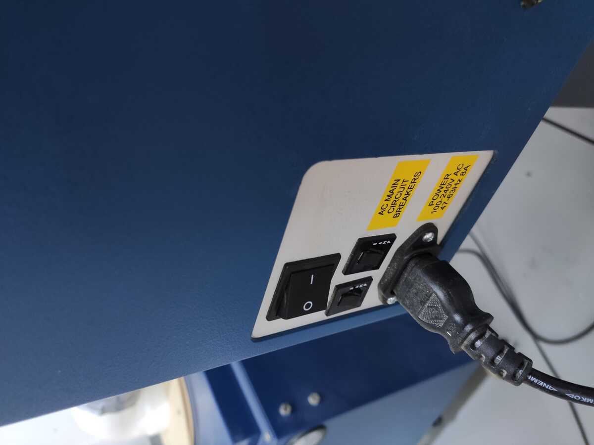
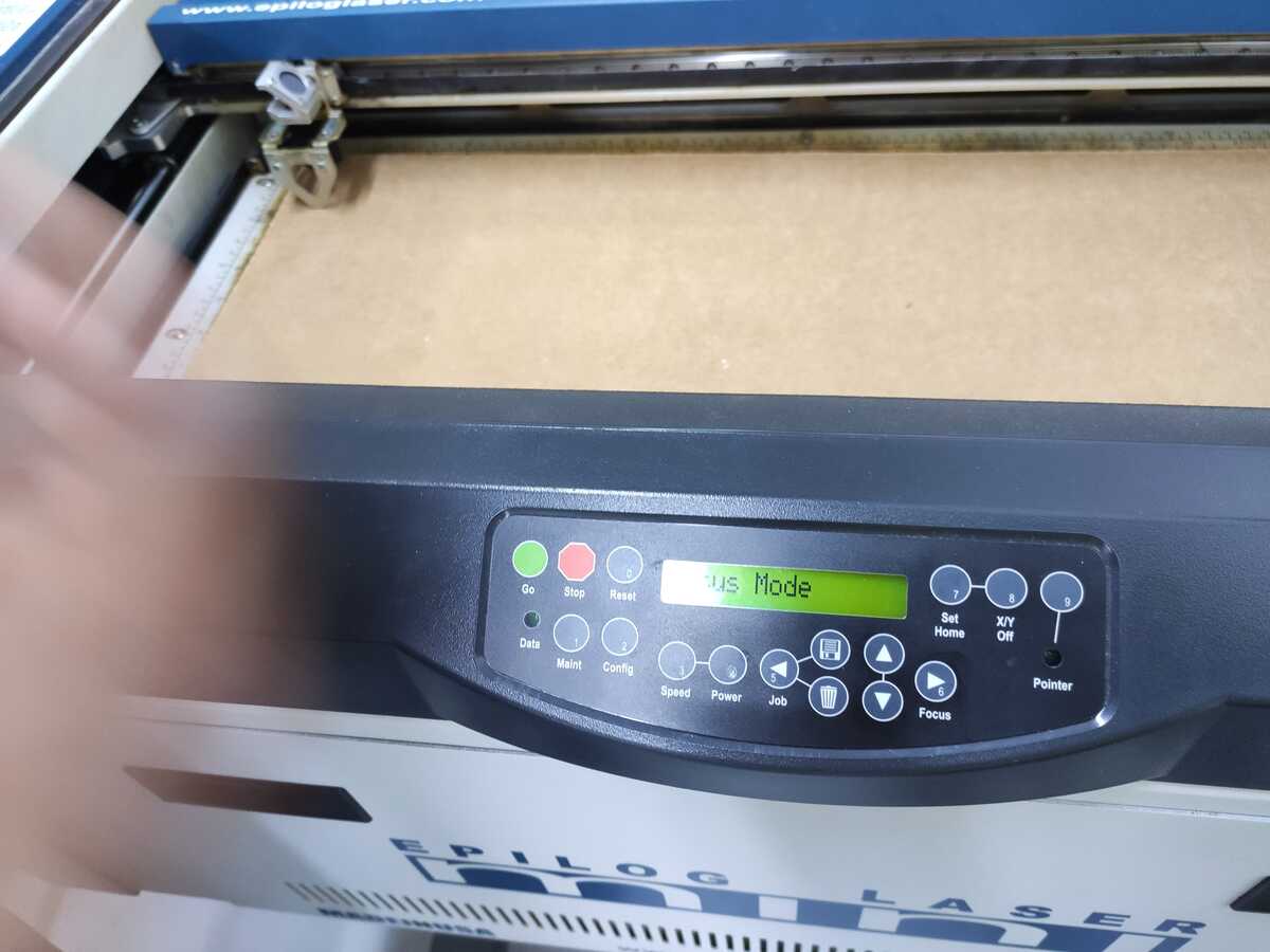
The laser can be turned on with the following sequence:
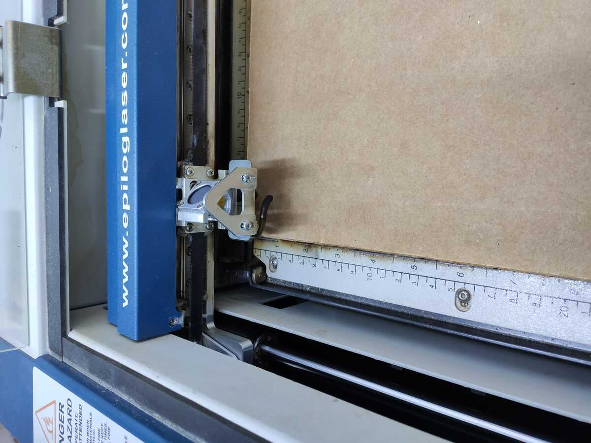
Another important thing that should be accomplished before printing with laser is fixing its focus. In order to do so, the laser has a triangular piece, which is magentic and can be placed on top of the lense holder. By turning the piece down and making sure its tip is just touching the material to be cut the focus is adjusted. Once that is accomplished, the triangular piece should be turned around and stored on top of the lense holder. The left image shows the focusing process, and the right image shows the placement of the piece after focus is adjusted.
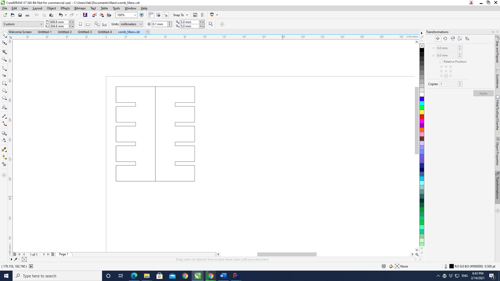
In order to characterize the kerf of the lasercutter, the following comb was created. Below you can see the initial design in FreeCAD before any constraints are applied:
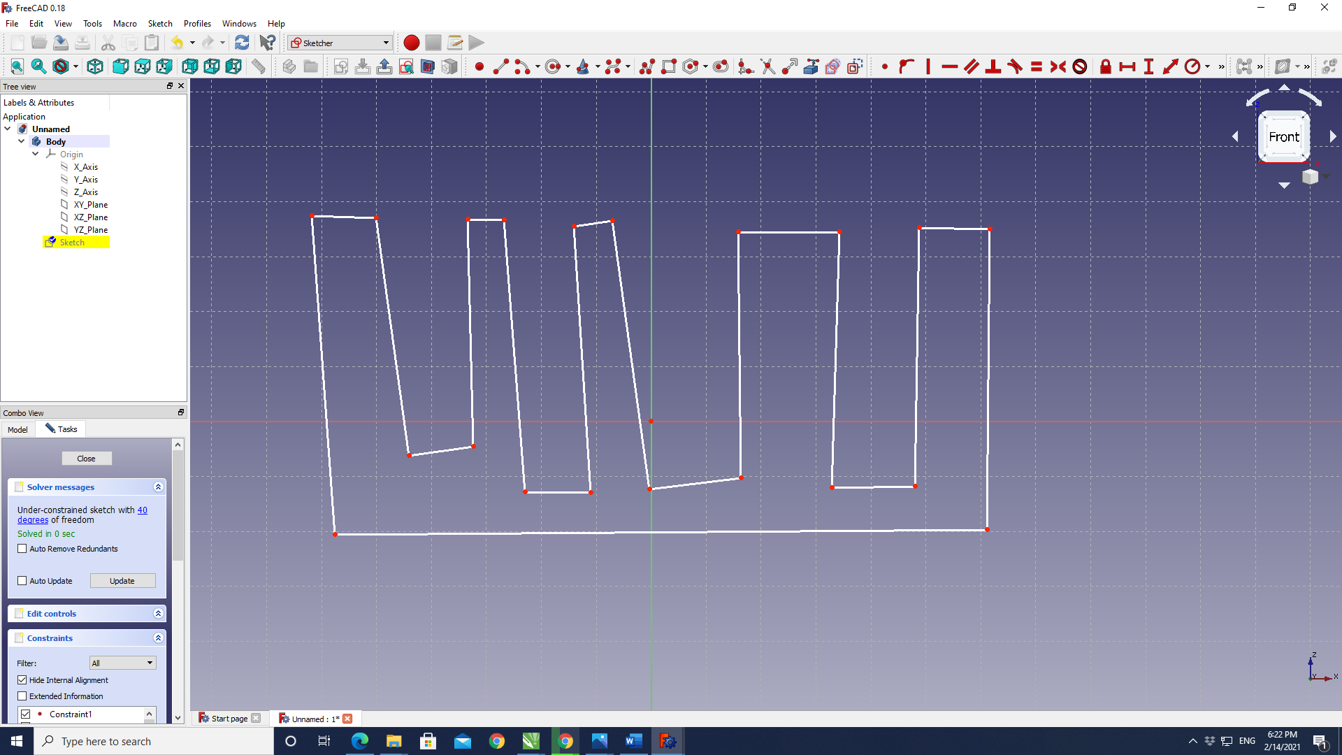
After constraining it, its dimensions were made parametric, with each subsequent dent increasing 0.05mm, starting at 3.80 mm, as the thickness of the cardboard was measured at 3.97 mm with a micrometer and there were 4 dents.
The comb was then exported as an svg and opened with CorelDraw, where two mirrored combs were created to print:
More about the kerf and other lasercutter characteristics can be read at the Dilijan Fab Lab's 2021 website.
The combs were then lasercut and while the 3.80 mm dents were slightly loose, the 3.95 mm dents were almost too tight. I decided to make the pieces a bit tighter as it is a construction kit and playing with the pieces will eventually somewhat bend the edges and make it looser.
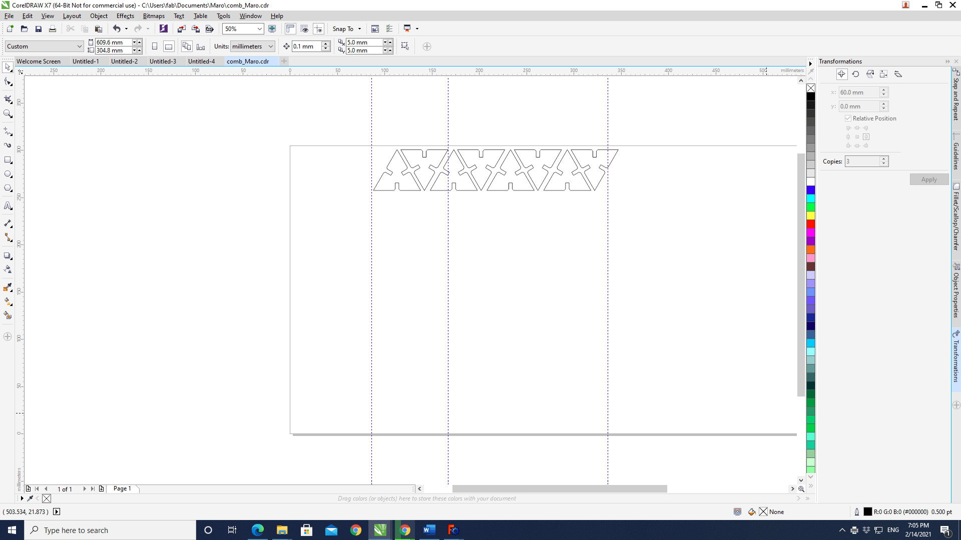
The construction shapes drawn with FreeCad were exported as 2D images, which were then opened by CorelDraw to place in a packed manner and then they were sent to the laser cutter.
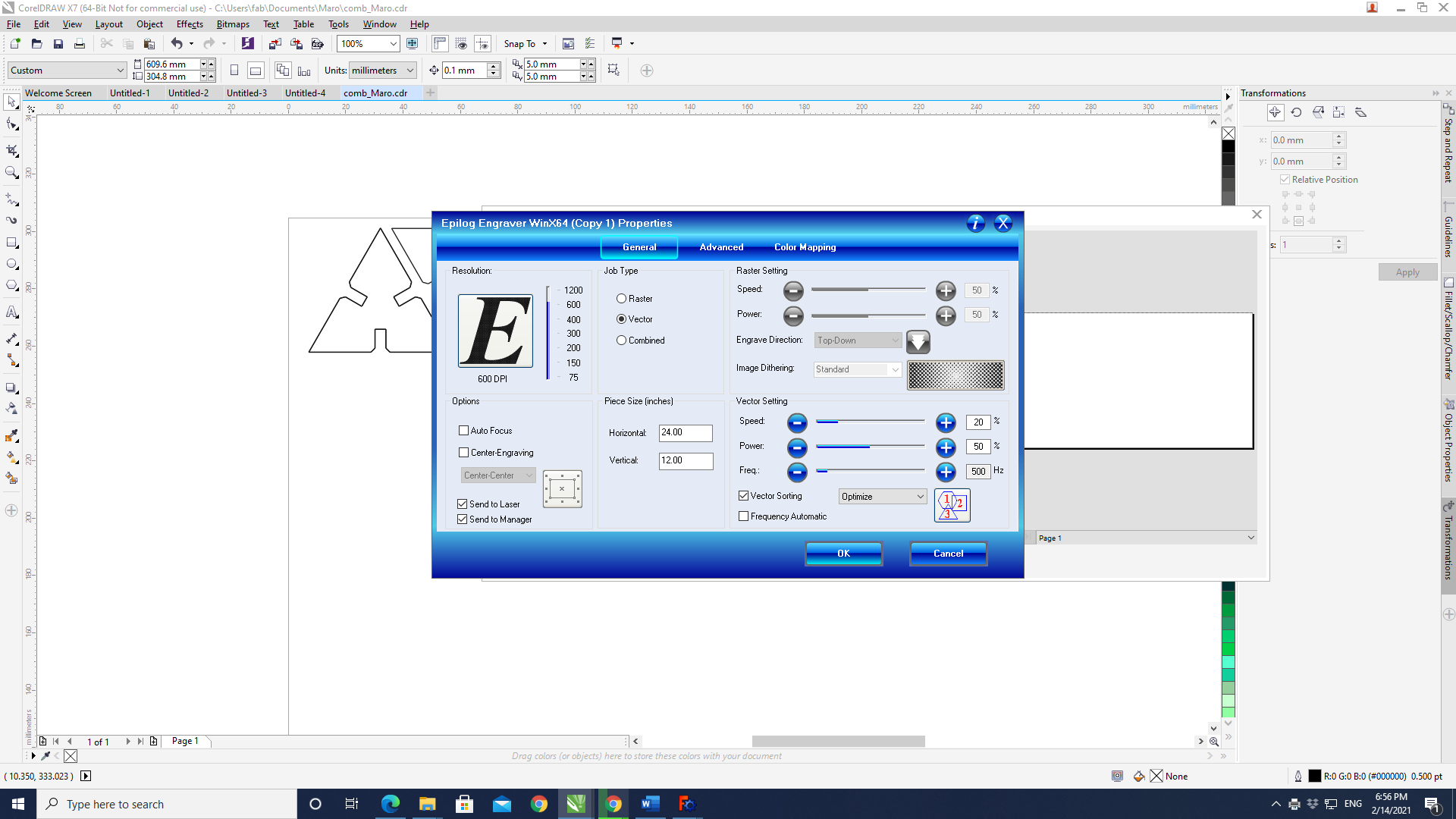
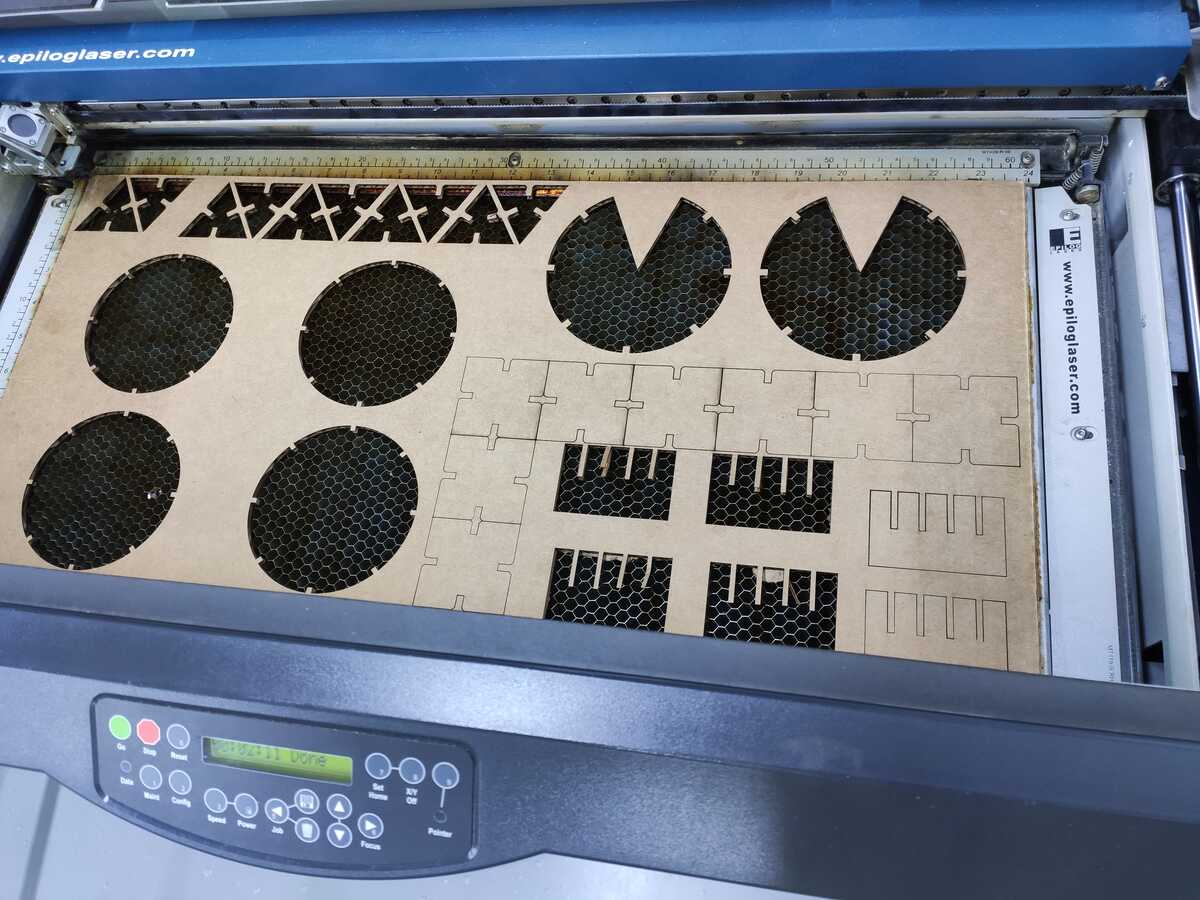
The lasercutter settings could be adjusted through the following window. Initial values were chosen from the device manual, and after some tweeking, the best values for cutting carboard using a vector image were settled on to be 20% for the speed, 50% for the power, and a frequency of 500 Hz.
The shape to be printed was packed in such a way to save material. Sharing an edge would also allow on preserving the cutter besides saving material and energy. Another important thing to remember is to set the thickness of all the edges where the laser is going to pass to 'hairline' in CorelDraw, or 0.01 mm.
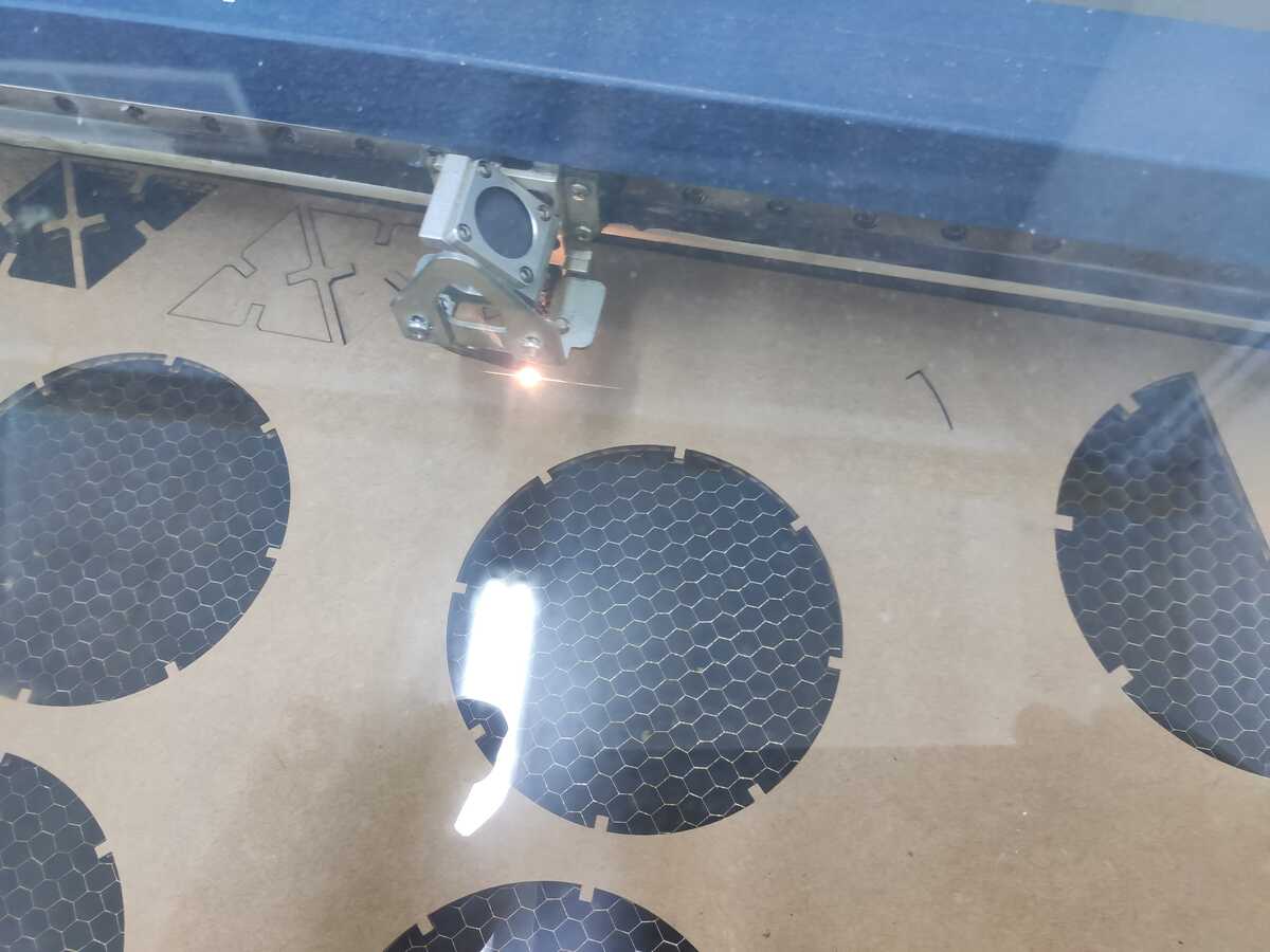
The laser then proceeded to cut out the construction shapes:
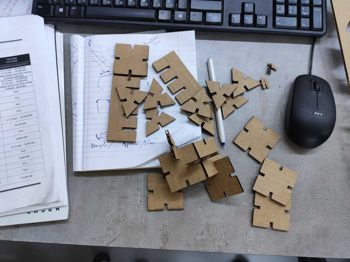
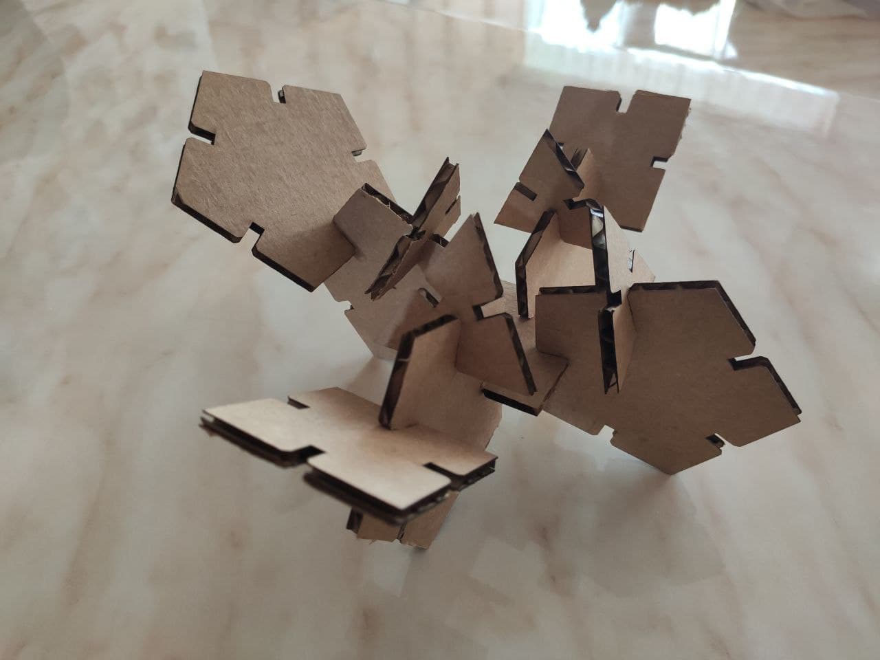
Here the final results can be seen:
Is it a bird?... Is it a plane?...
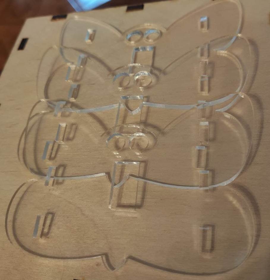
For the final project, I had to use the lasercutter to make the butterfly box cover from acrylic. The details can be viewed on project's page.
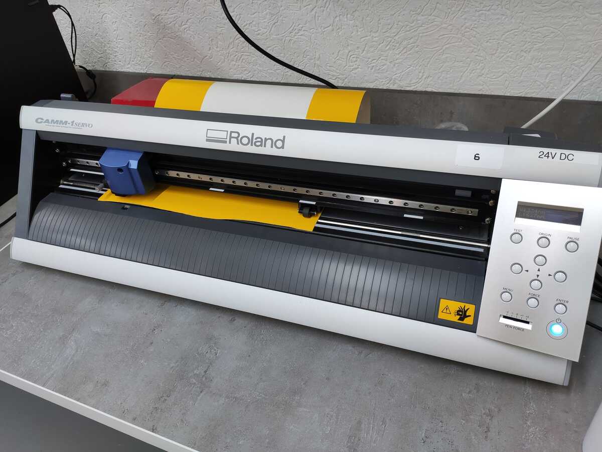
The vinyl cutter
Fab Lab Dilijan uses a Roland GX-24 vinyl cutter. It ended up being a fairly straight forward device, pleasant to use.
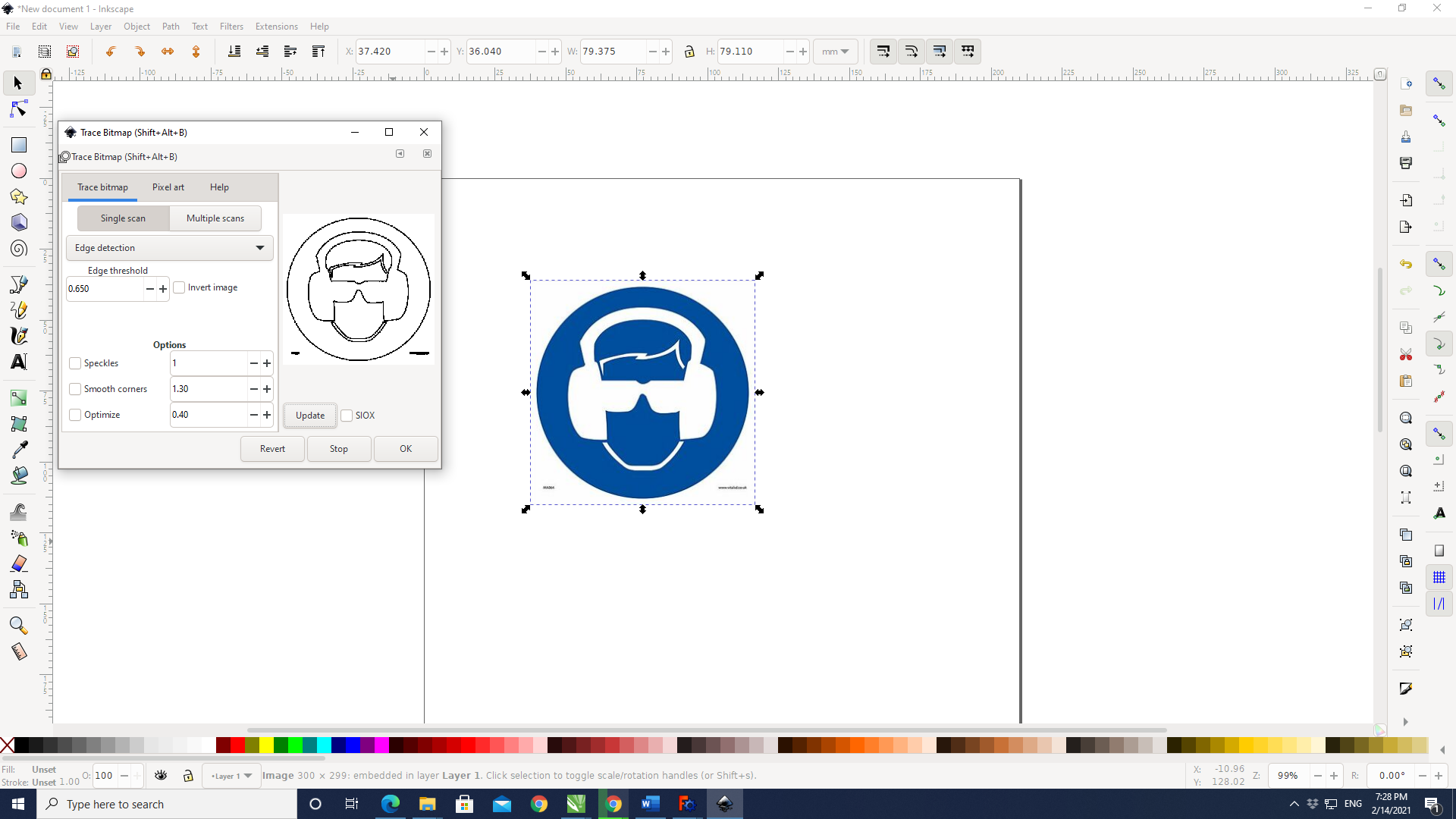
For the sticker, I decided to make one for eye and ear protection at the lab, which could be used for the room where the CNC cutter is located. In order to do so, I downloaded a standard existing protection from the internet, and set about modifying it in Inkscape.
Initially, I used the Trace Bitmap feature of Inkscape to trace the image to convert it to a vector image:
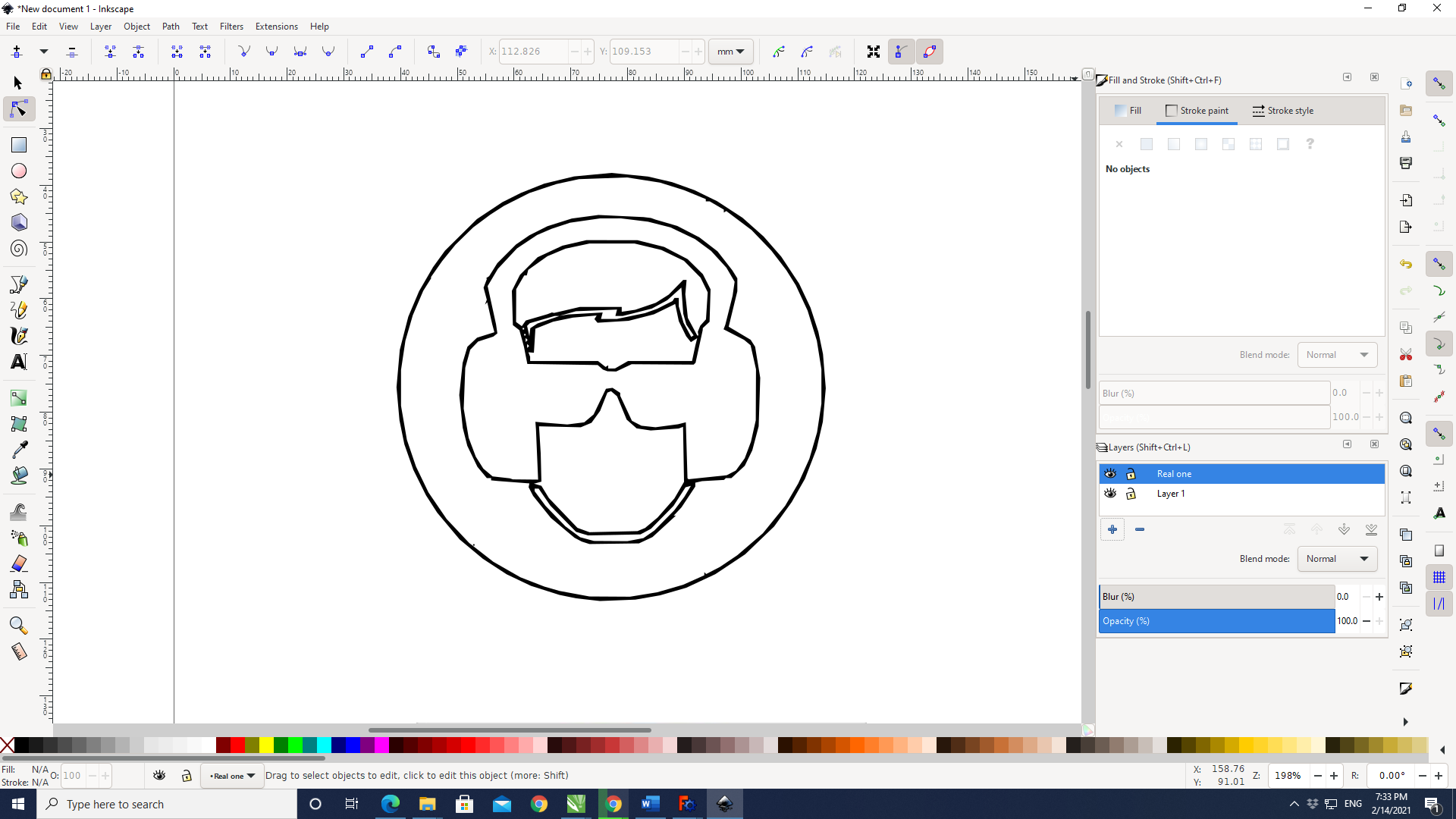
This was the resulting image:
I then changed certain features such as removing the top hair and adding a ponytail.
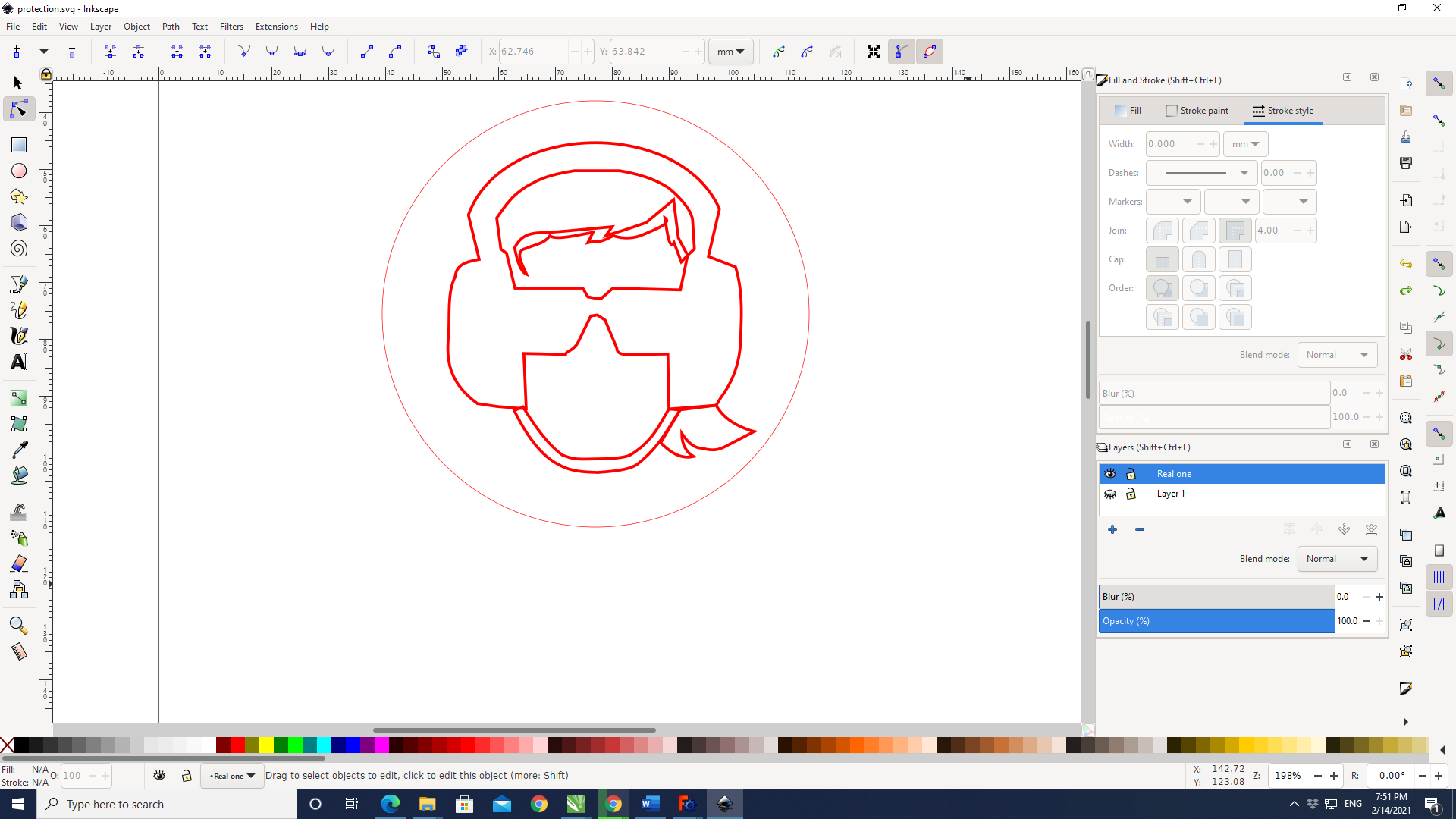
The vector file generated was then saved as .svg and trasferred to the computer attached to the vinyl cutter.
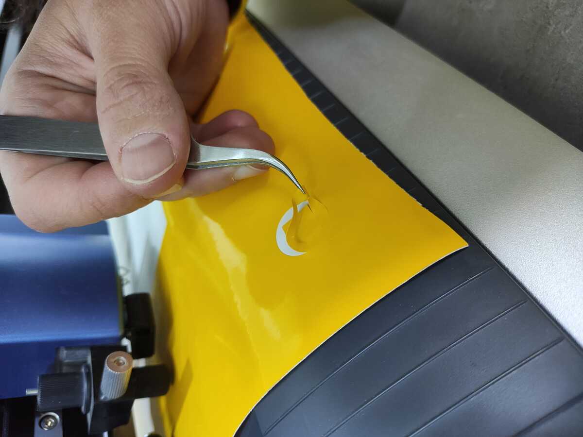
Again, to use the device, we were referred to the manual, especially the safety instructions. Before using the device, we had to do a test cutting, where removing the square around the circle had to be clean, without the two sticking to each other, and then after removing the circle, there had to be faint traces left on the paper beneath. If the test failed in any way, the force of the knife would have to be adjusted:
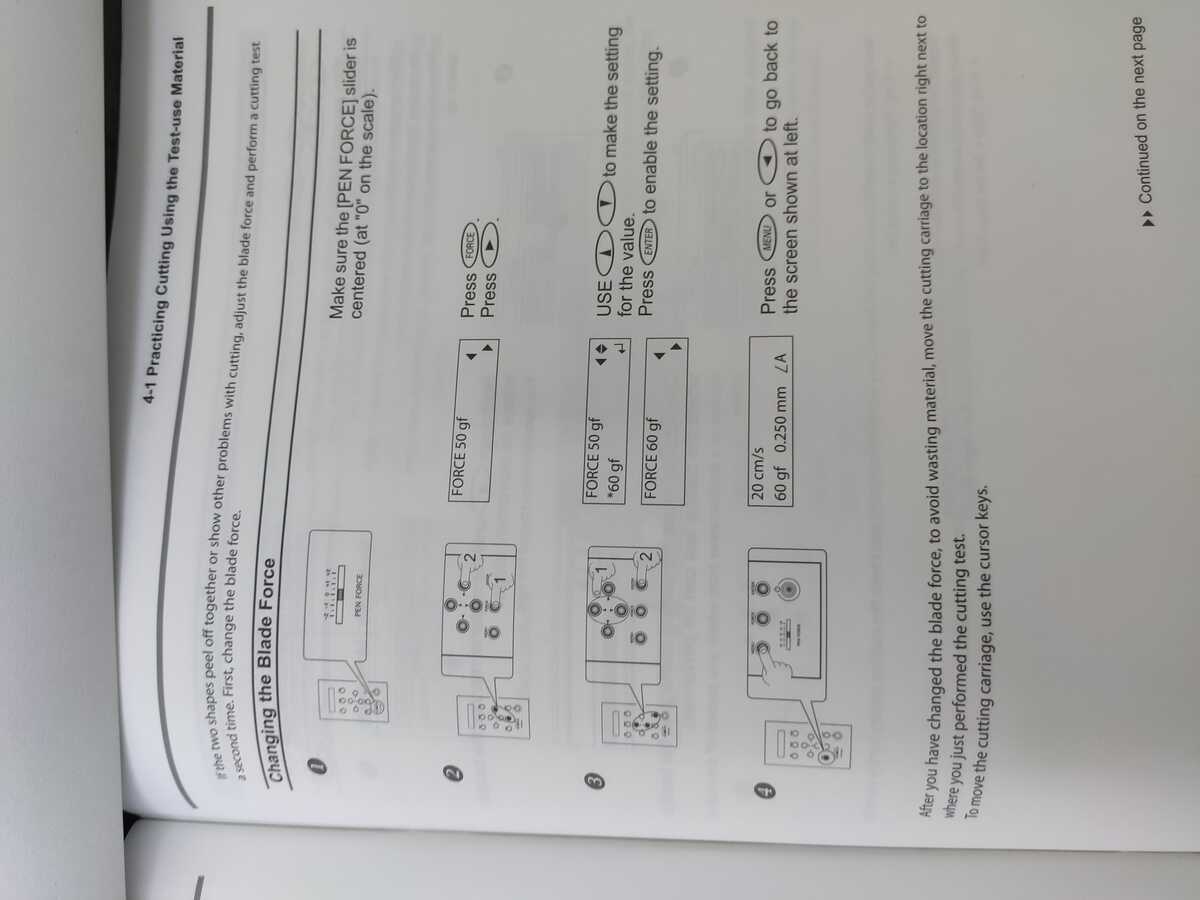
In order to adjust the force of the blade to get the square around the circle out cleanly, we were referred to the instruction manual to tweak it:
The computer attached to the vinyl cutter carries the proprietory software CutStudio which can itself be used to create
an .svg or .dxf design to cut or import it.
In order to set up the correct size for the page, under File -> Cut Setting the dimensions of the vinyl
placed under the vinyl cutter can be directly obtained from the machine (it must be on).
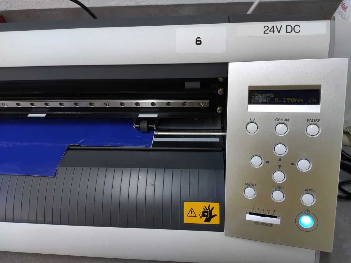
The final blade force for cutting the protection sign was adjusted to be 170 gram-force, and the speed was set as 15 cm/s as can be confirmed from the screen of the vinyl cutter below:
In my case, I simply opened the vector file I had created with Inkscape in CutStudio, obtained the size of the vinyl sheet
from the machine directly into the software, and then cut it using File -> Cutting....
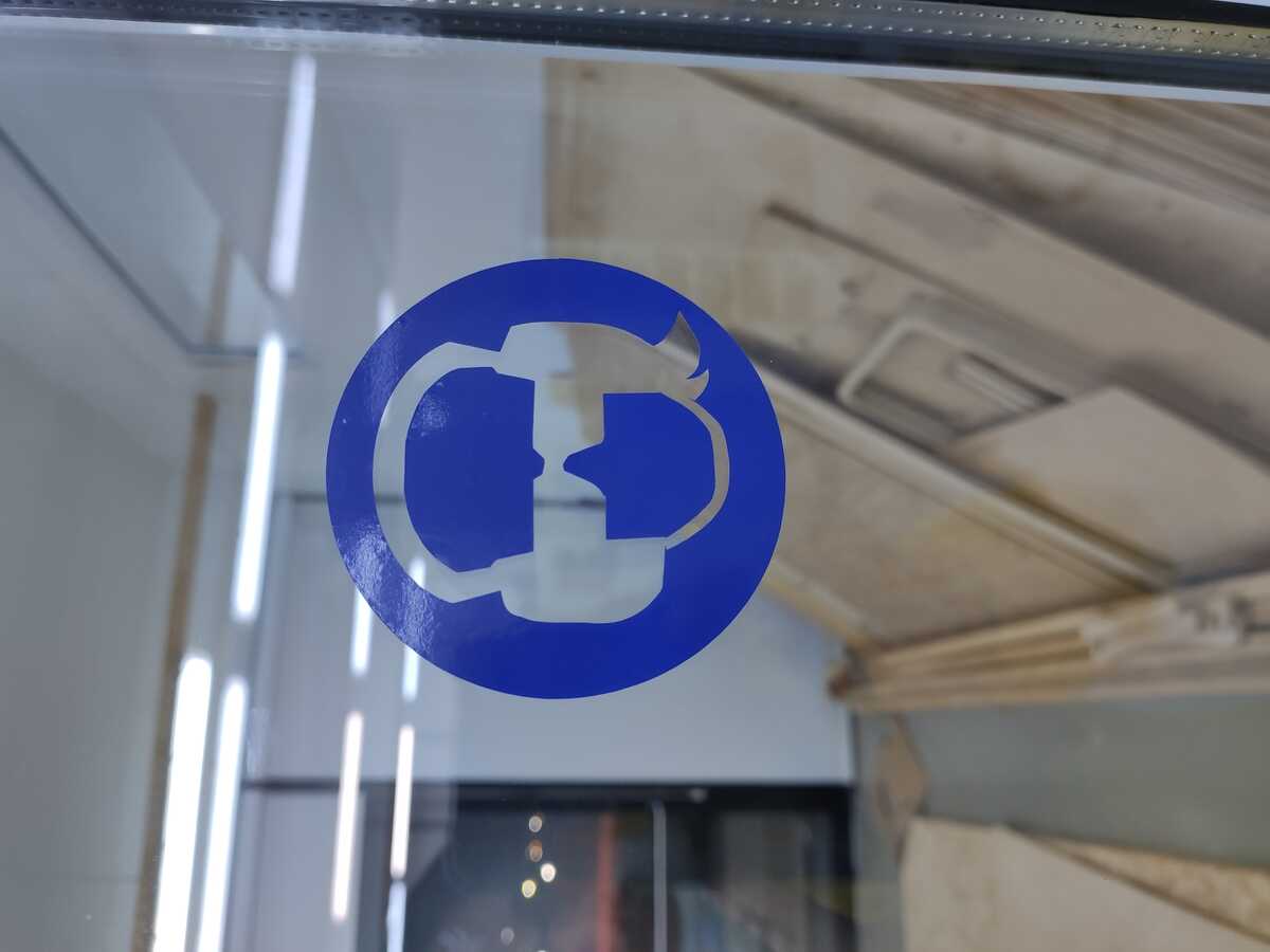
Here is the final result:

Here is the final result proudly displayed at the entrance of the CNC room:
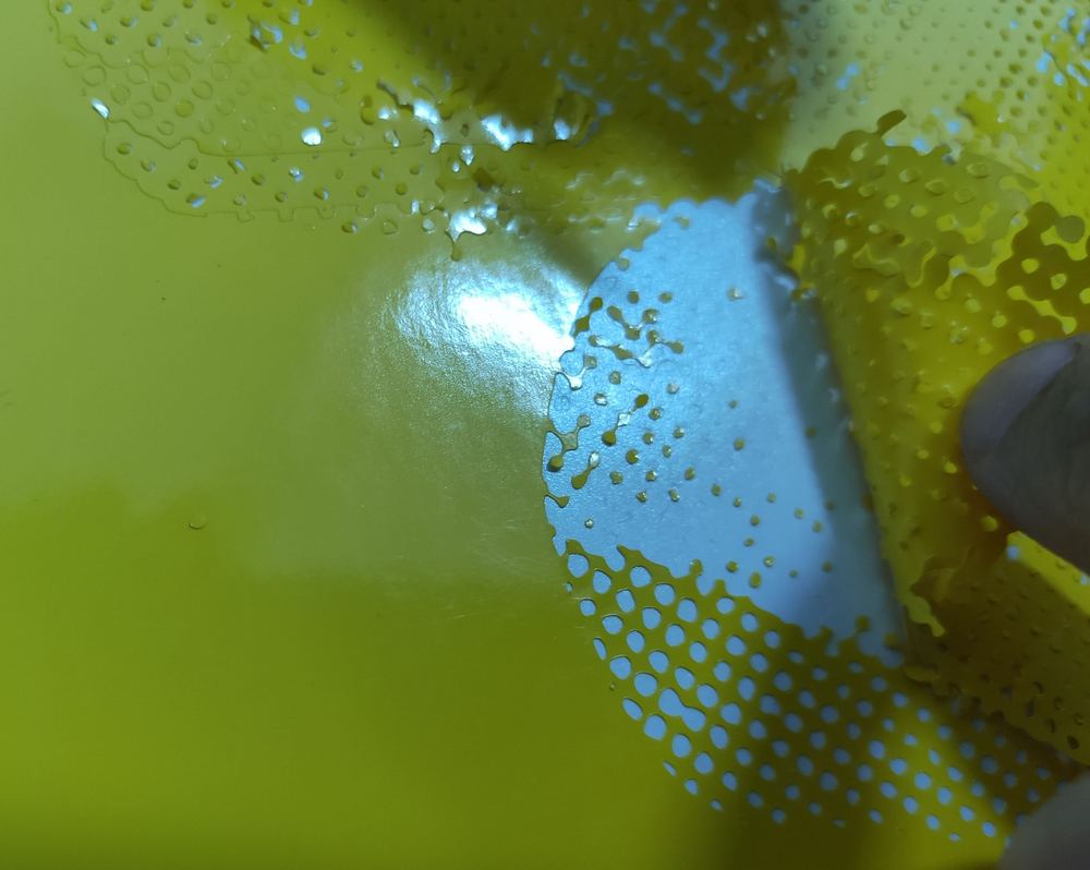
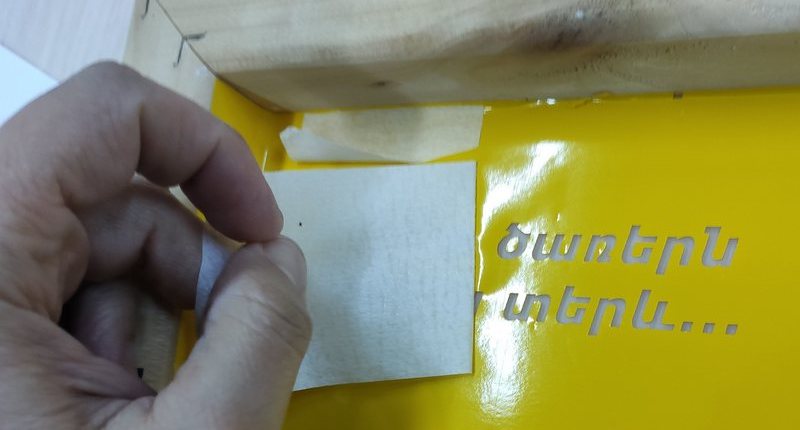
I revisited the vinyl cutter in the wildcard week, where I cut out a halftone image, and a poetry verse. Details can be followed in the corresponding page.
Downloading the files
The files for this week can be downloaded from the following links:
- The parametric construction kit design (FreeCAD file with .FCStd extension, 25 kB)
- Eye and ear protection image (.svg, 38 kB)

