3D Scanning and Printing
The assignment for this week was to design and 3D print something that can only be manufactured additively and not subtractively. So basically something that can't be done by cutting and milling, and would have to be manufactured layer by layer (or in slices).
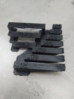
For the group assignment, we had to test the design rules for 3D printing, which can be viewed here.
Things that could be manufactured additively but not subtractively could include (but not be limited to):
- Any closed hollow object,
- Any object inside a closed object,
- Separate pieces that are inserted into each other or linked with closed ends, so one cannot be detached from the other such as hinges, joints (such as ball joints), sliders, etc.
- Any object with an artifact (hole, trench) inside that is perpendicular to and accesible only from another narrow path.
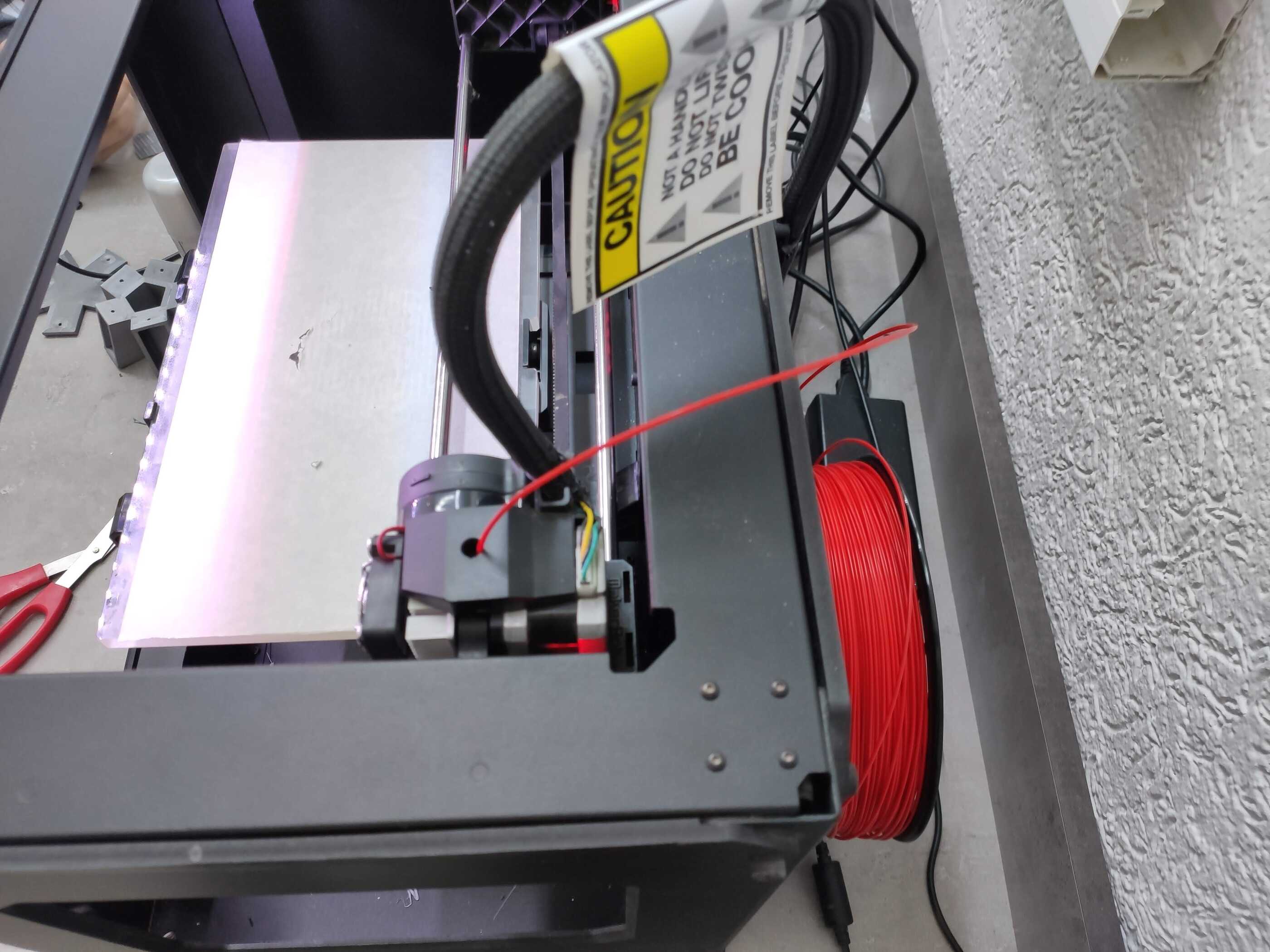
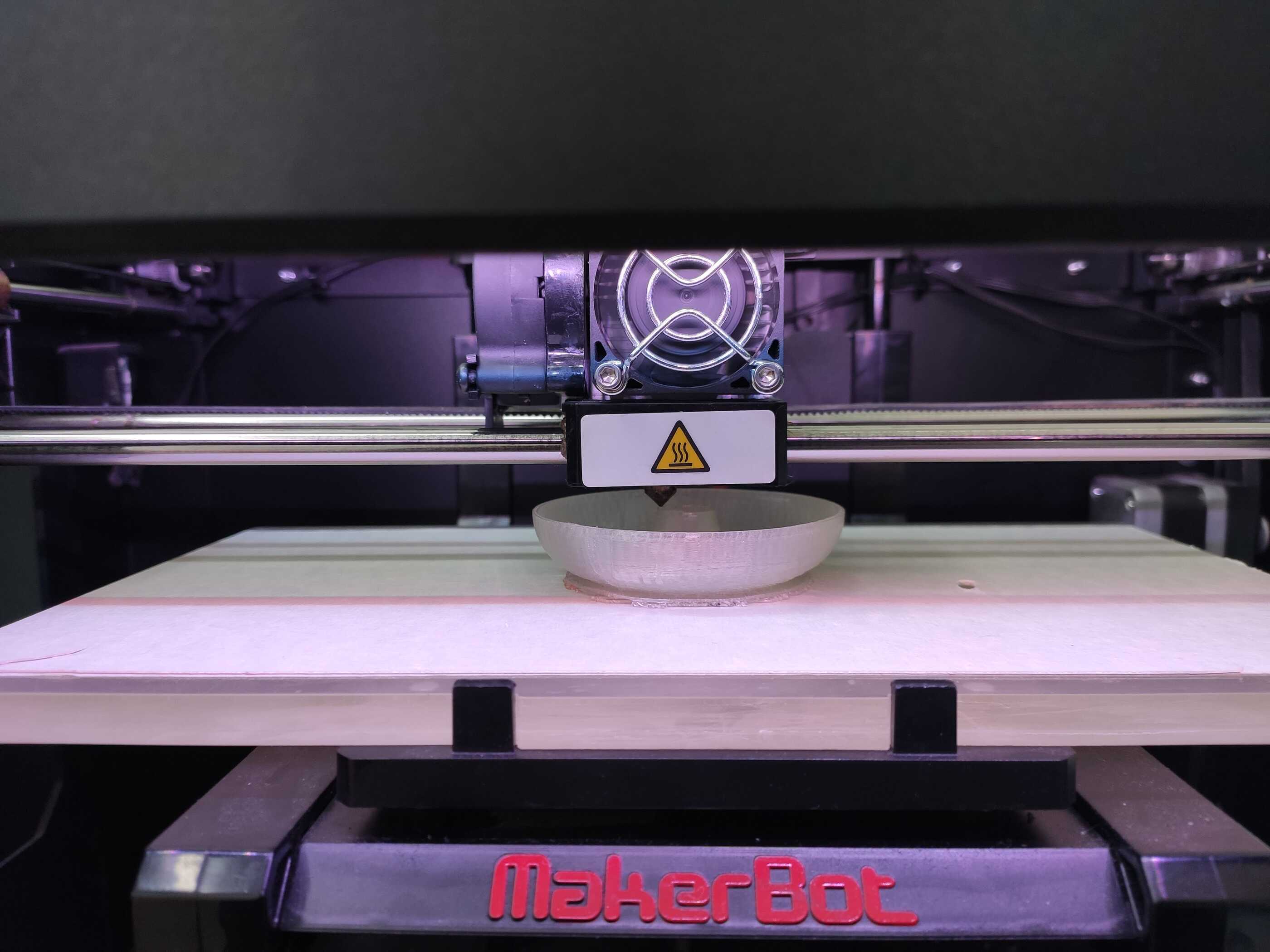
Description of the printer
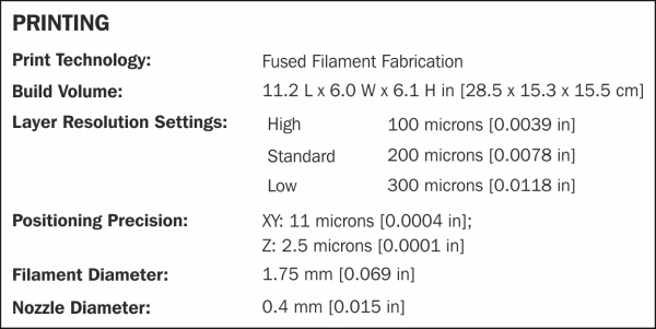
Dilijan Fab Lab uses two MakerBot Replicator 2 printers. They can build pieces up to 28.4 L x 15 W x 15 H cm (32.39 cm diagonal). They use nozzles with a diameter of 0.40 mm, which should be kept in mind in terms of what is the thinnest layer that can be achieved with such a printer.
Before using the printers, and from time to time, the leveling of the printing tray has to be adjusted through three adjustment screws tightening and loosening three screws underneath the tray and using a piece of paper to gauge the friction between the printing nozzle and the tray. The main menu of the printers has a command to guide through the leveling process.
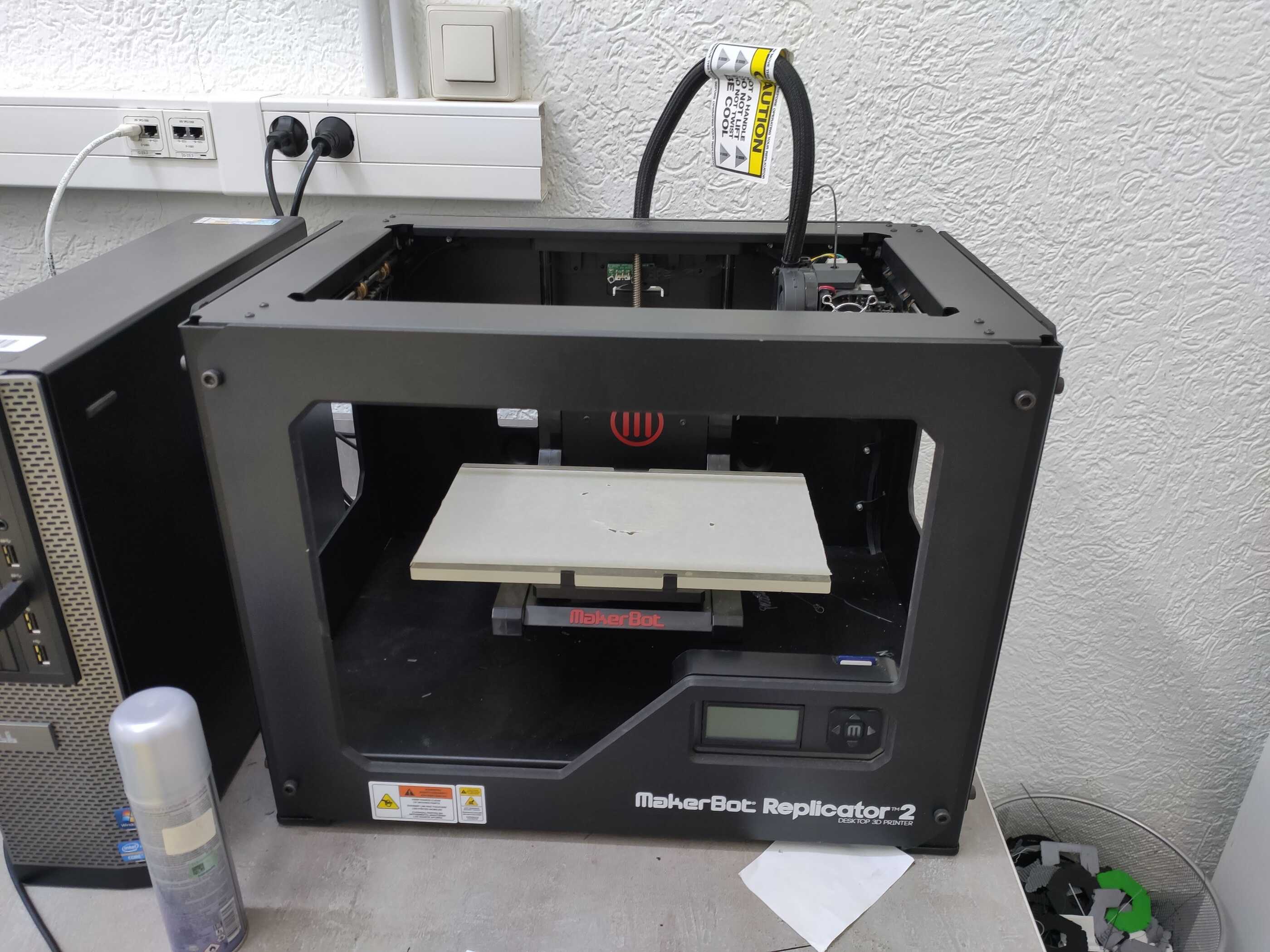
The printing material available in the lab is PolyLactic Acid (PLA), a bioplastic, in various colors.
The roll for the PLA is located behind the printer and the PLA should be rolling off of it in a clockwise manner.
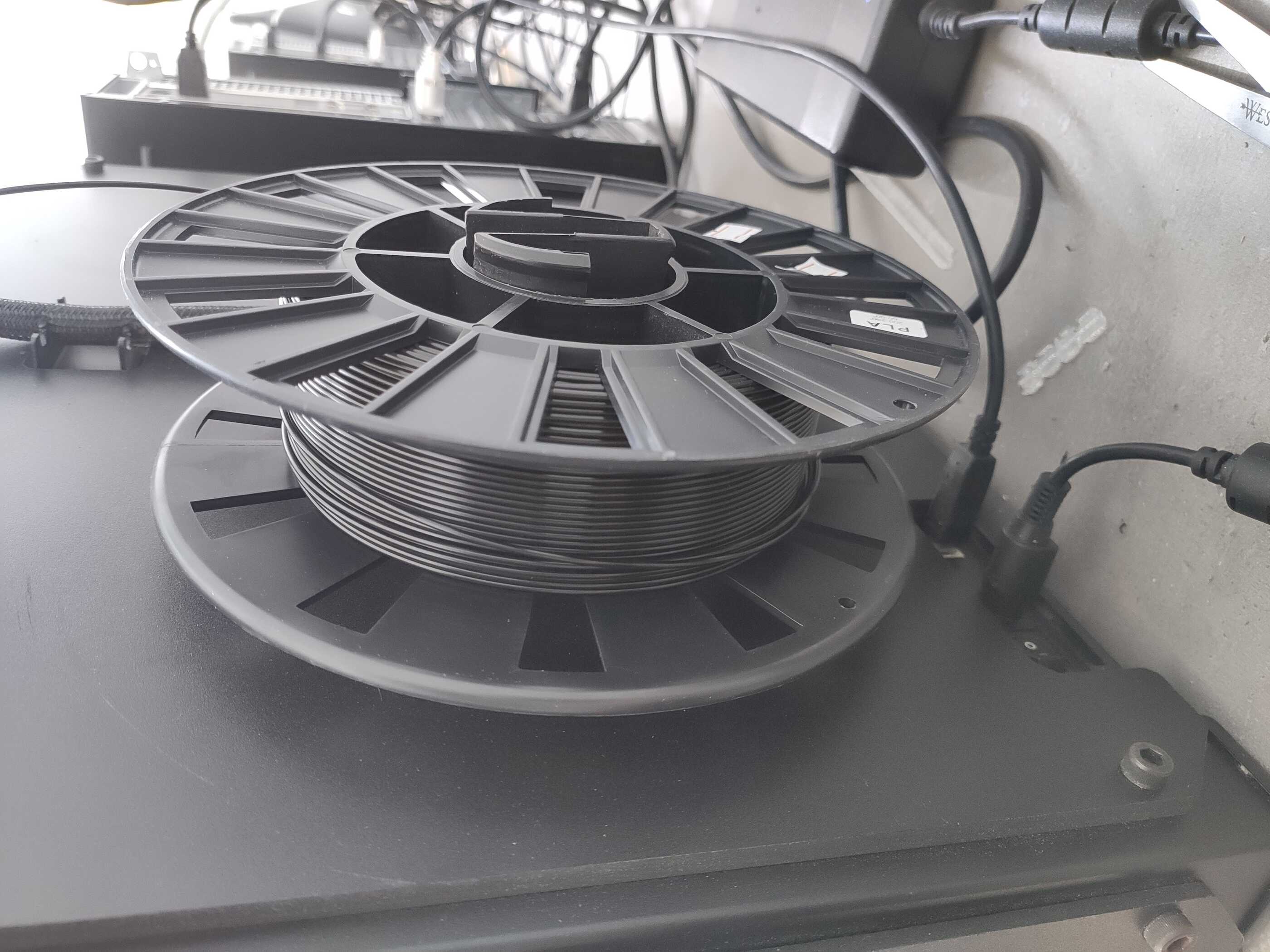
The PLA can be changed using the Unload and Load functions of the menu under Changing the Filament. During both operations, the printer heats the nozzle above 200°C to prepare it for extraction or insertion. The filament should then be pulled out and the new one inserted until the motor starts tugging on it, and then continue insertion for a few more seconds.
The printers have their own software, the Makerbot, which is a slicer, and can take .stl triagnular files and convert them to G-code for printing layer by layer. The software provides various settings, can create supports, and can show a preview of the slicing and estimate the time it would take.
To test the printers, the following was printed, which as can be seen, was not so successful in bridges and azimuthal angles between the layers.
Making an STL file from scratch and printing it
During the corresponding lecture, Neil Gershenfeld challenged us to write an .stl file (instead of generating it with a CAD software) and printing something with it. I found the challenge to be amusing and decided to read and see whether I could attempt that.
The two main 'tutorials' that I found online explainaing what an .stl file was and how to create it were this page and this page (from fabbers.com), especially the latter.
An StL (“StereoLithography”) file is a triangular representation of a 3-dimensional surface geometry. The entire surface is divided into triangles (which can be a lot when the file is generated by a CAD software). The triangles are defined in the file by the coordinates of their three vertices and the surface normal of the triangle pointing outward. The file does not contain any units or other information and the dimensions can be adjusted through the printing software.
The main rules to write an .stl file are as follows:
- Each triangle should share two vertices with another triangle.
- The vertices of the triangles should be input in a counterclockwise fashion when looking from the outside.
- The vertice coordinates should be positive-definite, so no negative or zero coordinates allowed.
- The vertice coordinates should be input in scientific E notation as e.g. 1.23456E+789.
Yes, these are pretty much the only rules. In fact, having to input the normal is really redundant since it could be calculated using the right-hand rule from the three vertices specified in counterclockwise order. Perhaps its input is required to make manufacturing faster and put the load of calculating the normals on the program that generates the .stl.
Stl can also be in ASCII or binary format.
Here's a sample showing how the code would look like in the ASCII format:
solid example

                        facet normal 1.42658E+000 1.03647E+000 -2.40399E+000

                            outer loop

                                vertex 4.5E+000 3E+000 1E+000

                                vertex 3.46353E+000 4.42658E+000 1E+000

                                vertex 4.73205E+000 5E+000 2E+000

                            endloop

                        endfacet

                        facet normal -0.54491E+000 1.67705E+000 -3.04457E+000

                            outer loop

                                vertex 3.46353E+000 4.42658E+000 1E+000

                                vertex 1.78647E+000 3.88168E+000 1E+000

                                vertex 2.58418E+000 5.9563E+000 2E+000

                            endloop

                        endfacet

                    endsolid example
Here 'facet' refers to each individual triangle. First the normal is specified. Note that the normal coordinates are the only ones allowed to be negative or zero.
Once I found out what the rules were, I decided I could give it a try.
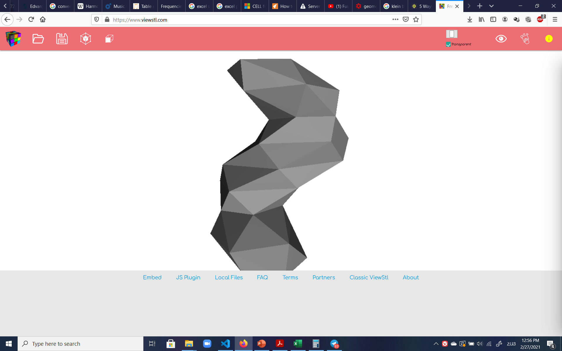
For the design, I decided to start from a pentagon base, and have nine pentagons on top of each other. Each pentagon's vertice would be connected to the corresponding vertice of the pentagon right above it. This would of course create five tetragons on each layer, and since the .stl required triangles, each tetragon would alo be divided into two triangles.
To make it more interesting, I decided to vary the sizes of the pentagons in each layer. I also decided to rotate each pentagon 30 degrees counterclockwise parallel to the same plane as the pentagon below it (in other words, the azimuthal angle wouldn't change throughout).
To make it extra interesting, I decided to have some translation motion of each layer, but in a way that would constitute a rotation along the z axis as the layers went up; in other words, a helical motion of the structure by 45 degrees in a clockwise manner.
I used Excel to perform all the calculations for the translational and rotational motions of each layer. Then I used the concatenate function of Excel to generate the code, and then pasted it in Visual Studio Code to get rid of extra quotation marks, fix the indentation, and save it as .stl.
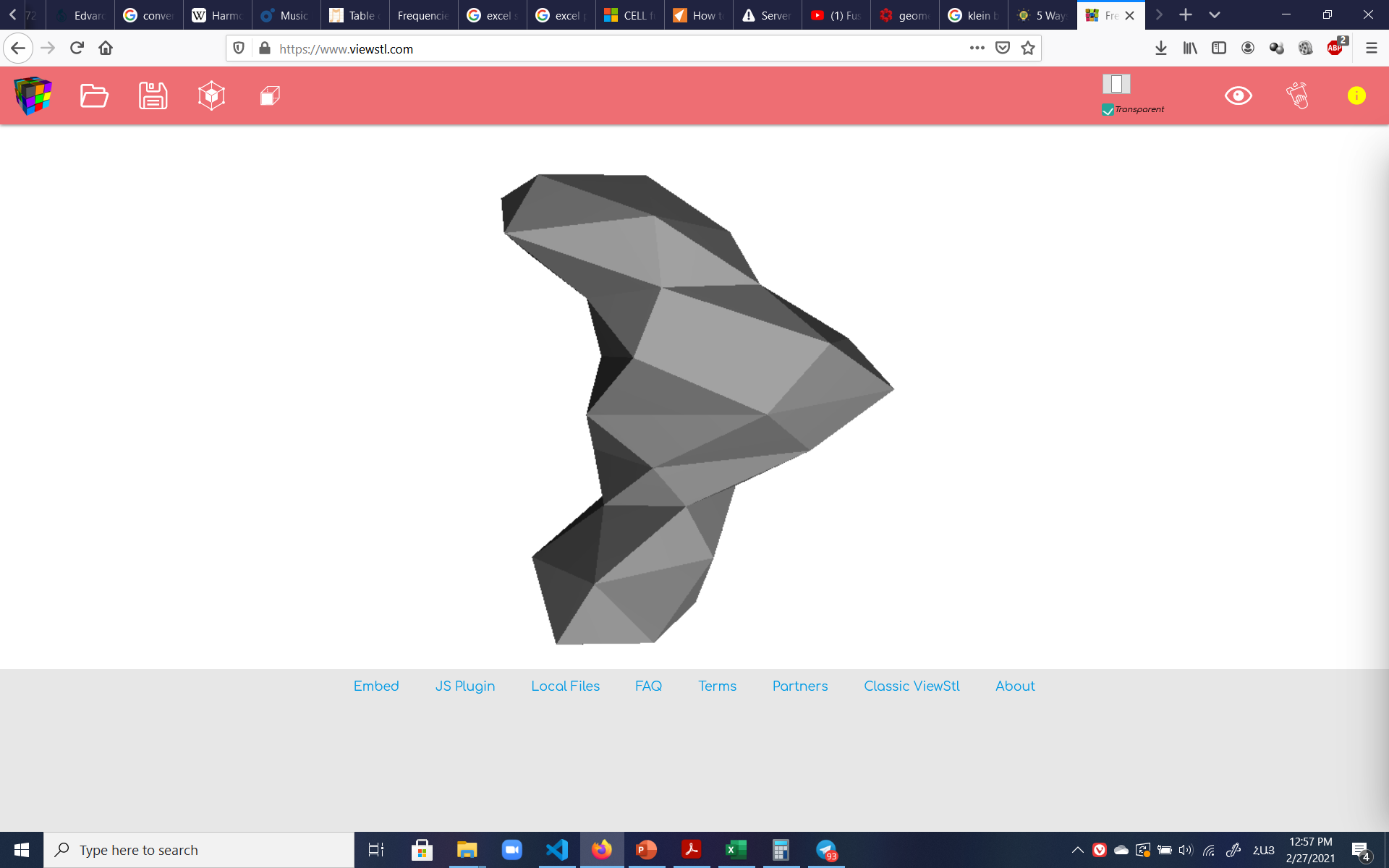
The final .stl file could be previewed and rotated online at viewstl.com:
I then took the file to the printers to be printed. Initially, the software wouldn't open the file (which the online previewer had previewed), until I realized I had forgotten a couple 'vertex' lines in the concatenation function of Excel and had to go back and regenerate the code. But once the typo was fixed, the .stl was read and printed like a charm.
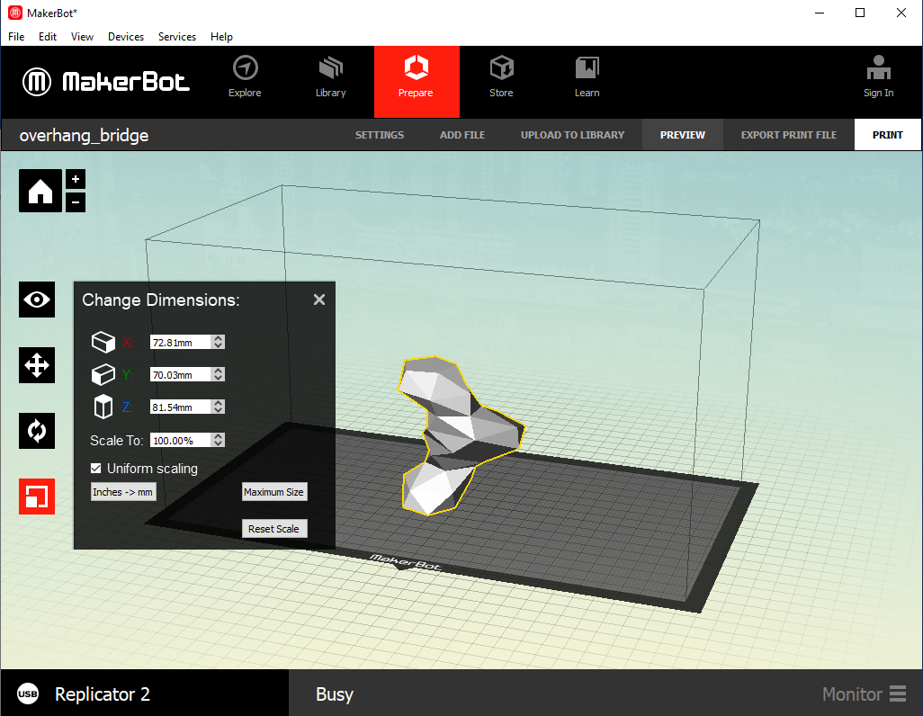
Here the slicer software allows the dimensions of the file to be set:
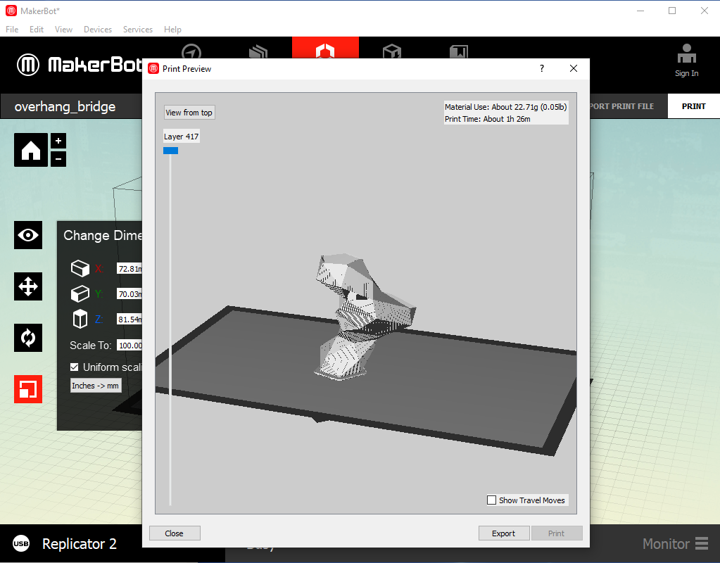
And here the slicer allows preview of the slicing and the print time estimate to be seen:
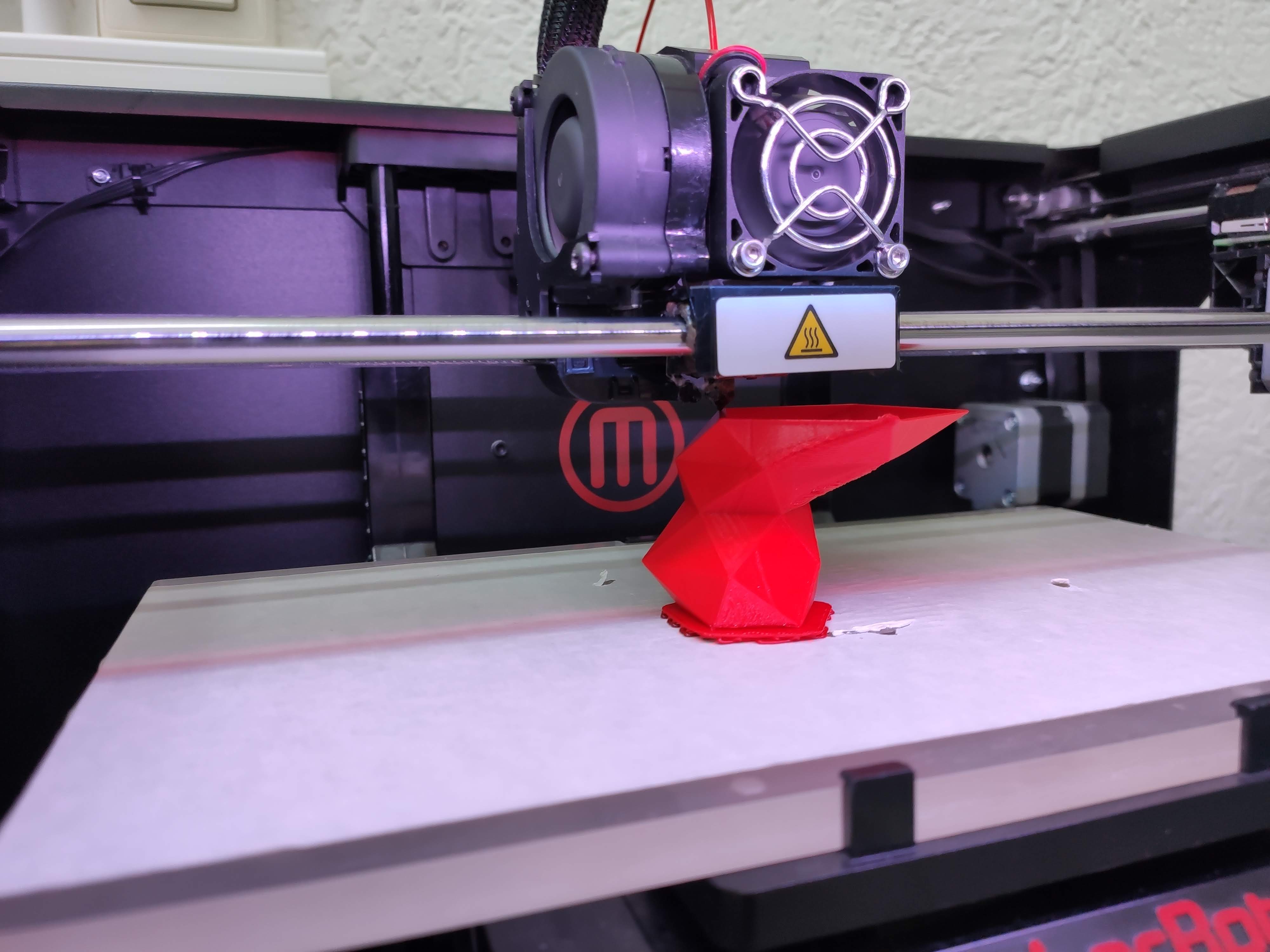
Here the beautiful 9 layer monster of triangles in being printed:
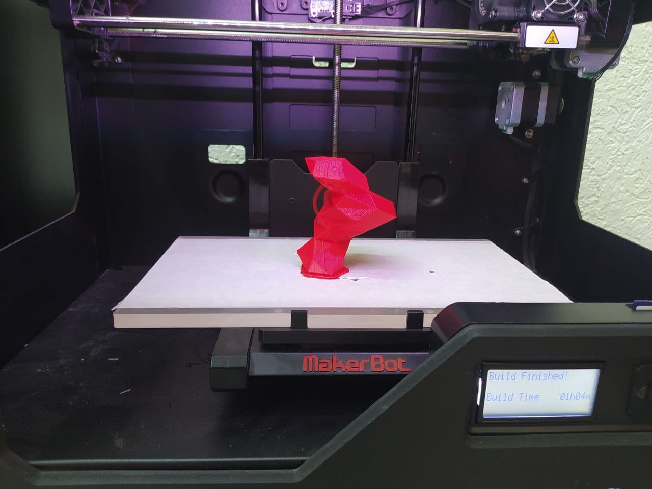
And lo and behold, here's the final result. From this angle, I was told it looks like the profile of a deer:
All the details of the calculations for creating the file are included in the Excel file whose link is at the bottom of the page.
Printing a Klein bottle
My next idea was to print a Klein bottle. Yes, you could say I have a slight obsession. Since the Klein bottle has only one surface, with the inside and the outside of the bottle touching, I think it would be hard to manufacture it subtractively. I believe subtractive manufacture of a Klein bottle would be possible if one had a device such as those used in laparsocopic surgeries where one had a machining tool in the end of a tube that could be inserted to remove material from the inside with excellent control, so in other words the machine equivalent of the legendary sister and brother duo who carved part of the Geghard Monestary inside a mountain in Armenia.
Since to my knowledge such a device does not exist (yet), it remains an affair for additive manufacturing.
I got help from the following video with the elegant design of Etienne K in designing the bottle using Fusion 360:
First, a couple sketches were created using Fusion 360:
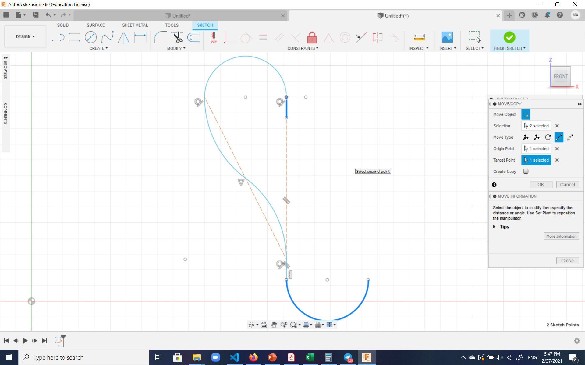
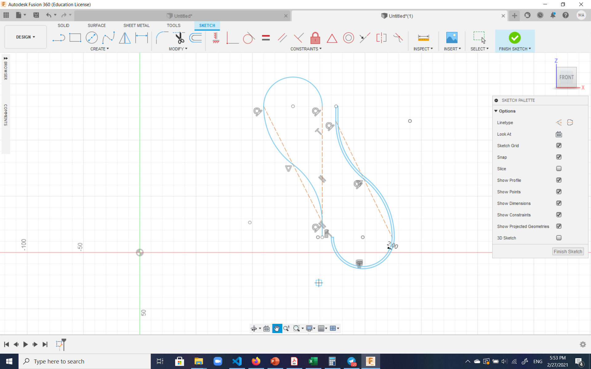
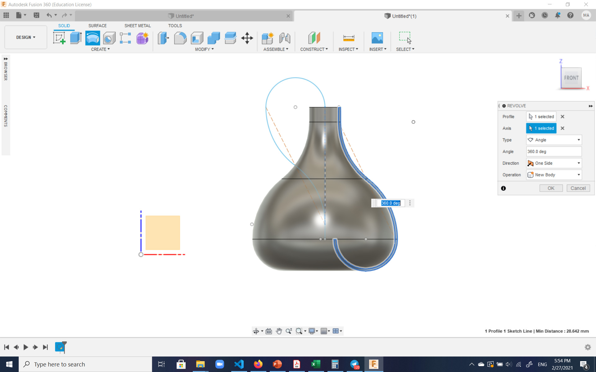
Then the body of the bottle was created by revolving the corresponding sketch:
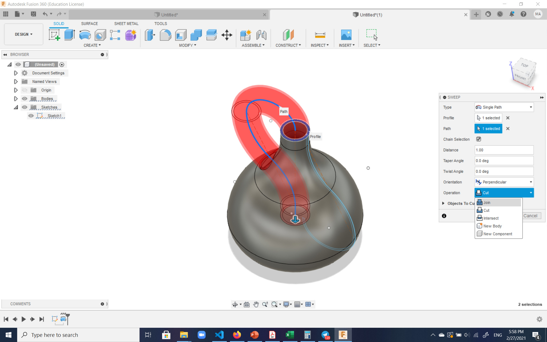
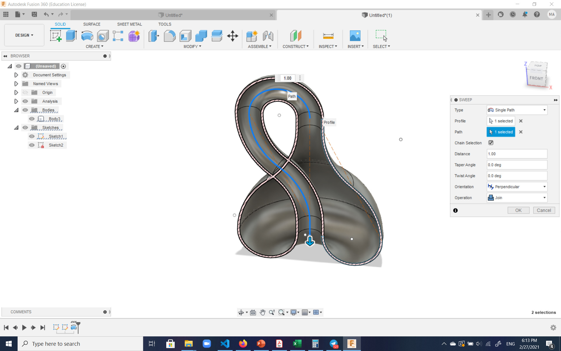
And finally, the bottle was inverted and attached to itself such that the inside and outside surfaces of it would become one. The was accomplished by sweeping one of the surfaces of the existing body along the sketched path:
In this cross-section one can see how the inside and outside surfaces of the bottle become one:
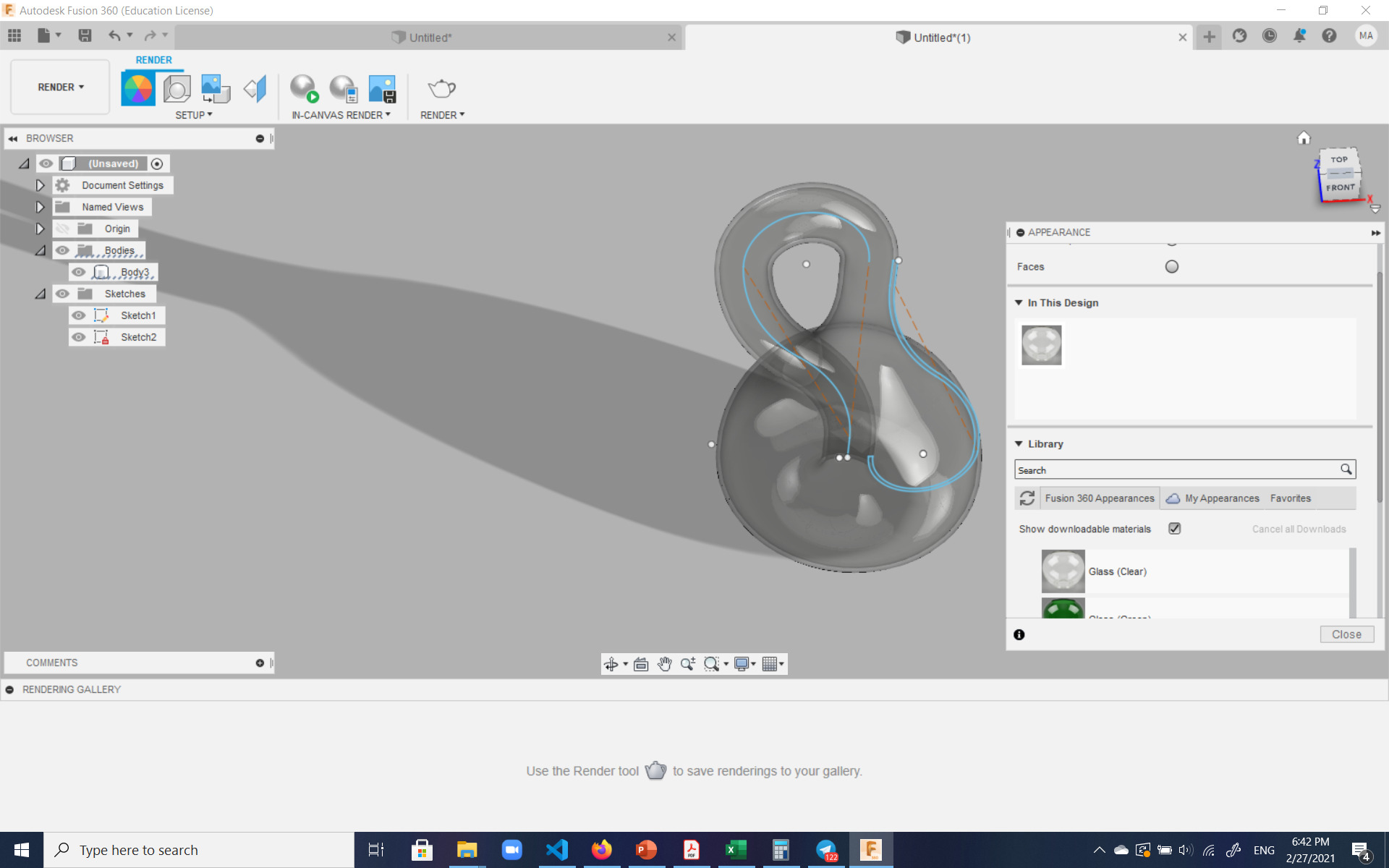
And here's the final beauty, rendered as glass:
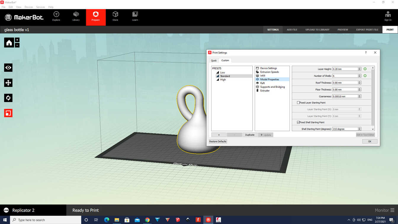
The corresponding .stl file was then exported from Fusion 360 to be input into the slicer program to print. The bottle was actually printed twice. Once as is with 6 shells, and once a smaller version with only 3 shells with my son's name embossed on it:

The settings in the slicer were set to 0.20 layer height.
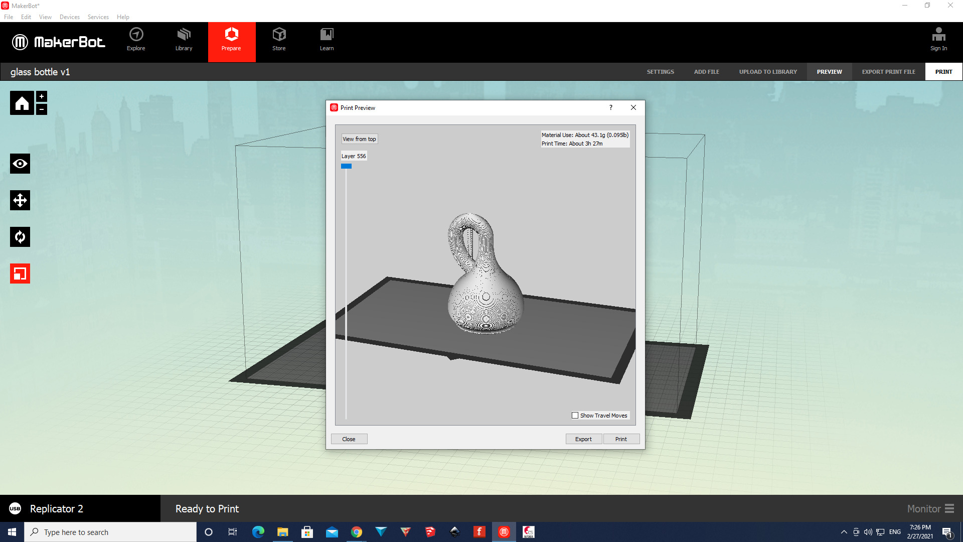
Here the preview of the first print can be seen. The program automatically created supports as shown:
And here this topological wonder is being printed. Additively. Layer by layer.
Here the final result can be seen with the supports still attached. These were not too hard to remove and were manually broken off.
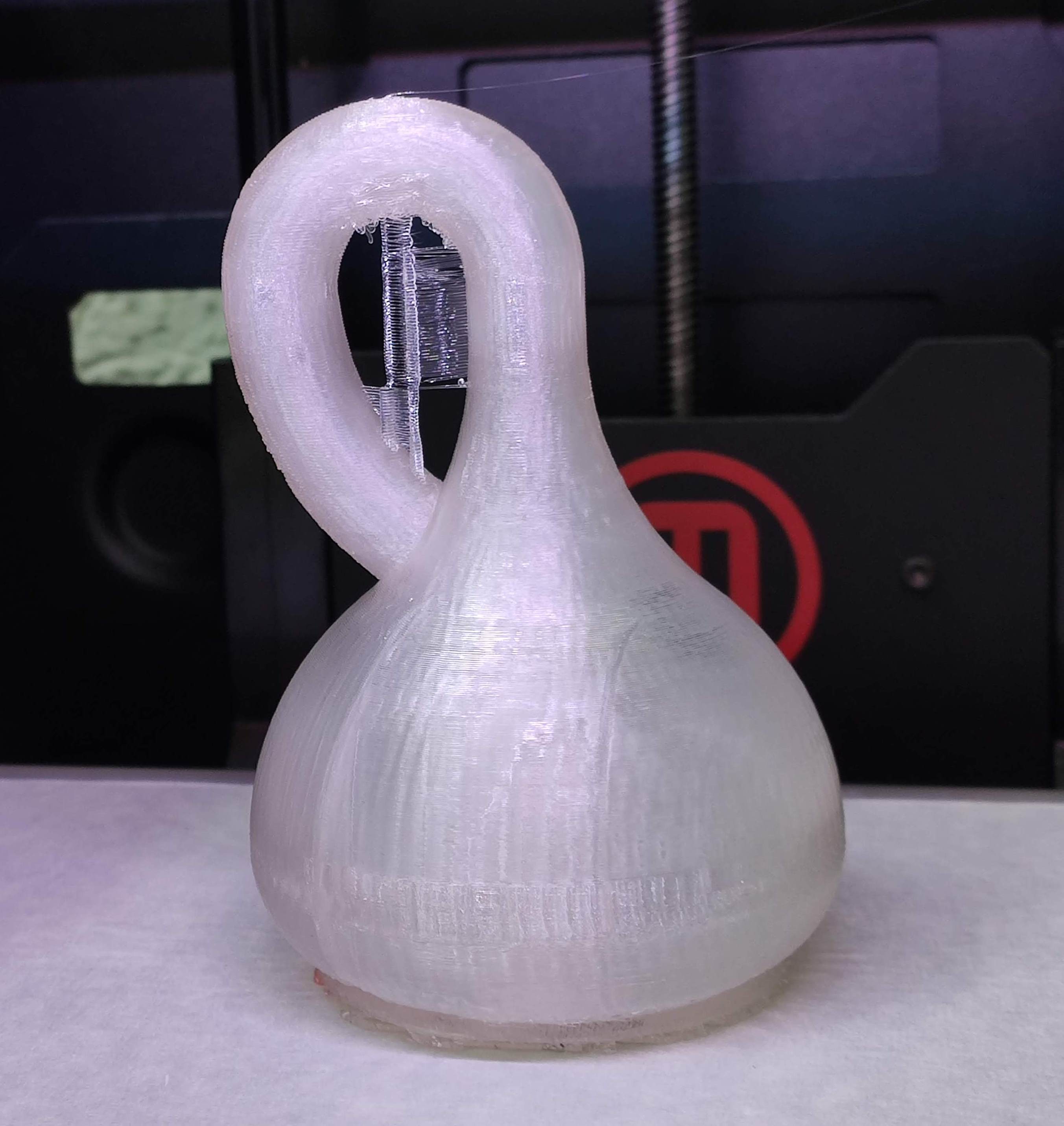
And here there is some light experimentation going on with the bottles. I had knowingly chosen an older and embrittled PLA to print as it was transparent for the inside to be seen. A fair amount of transparency is still to be desired, though. The left one is the smaller one with 3 shells and no support (the name is embossed on the other side and ended up making a hole there). The right one is larger with 6 shells and was printed with support.
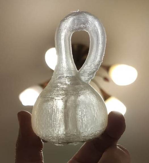
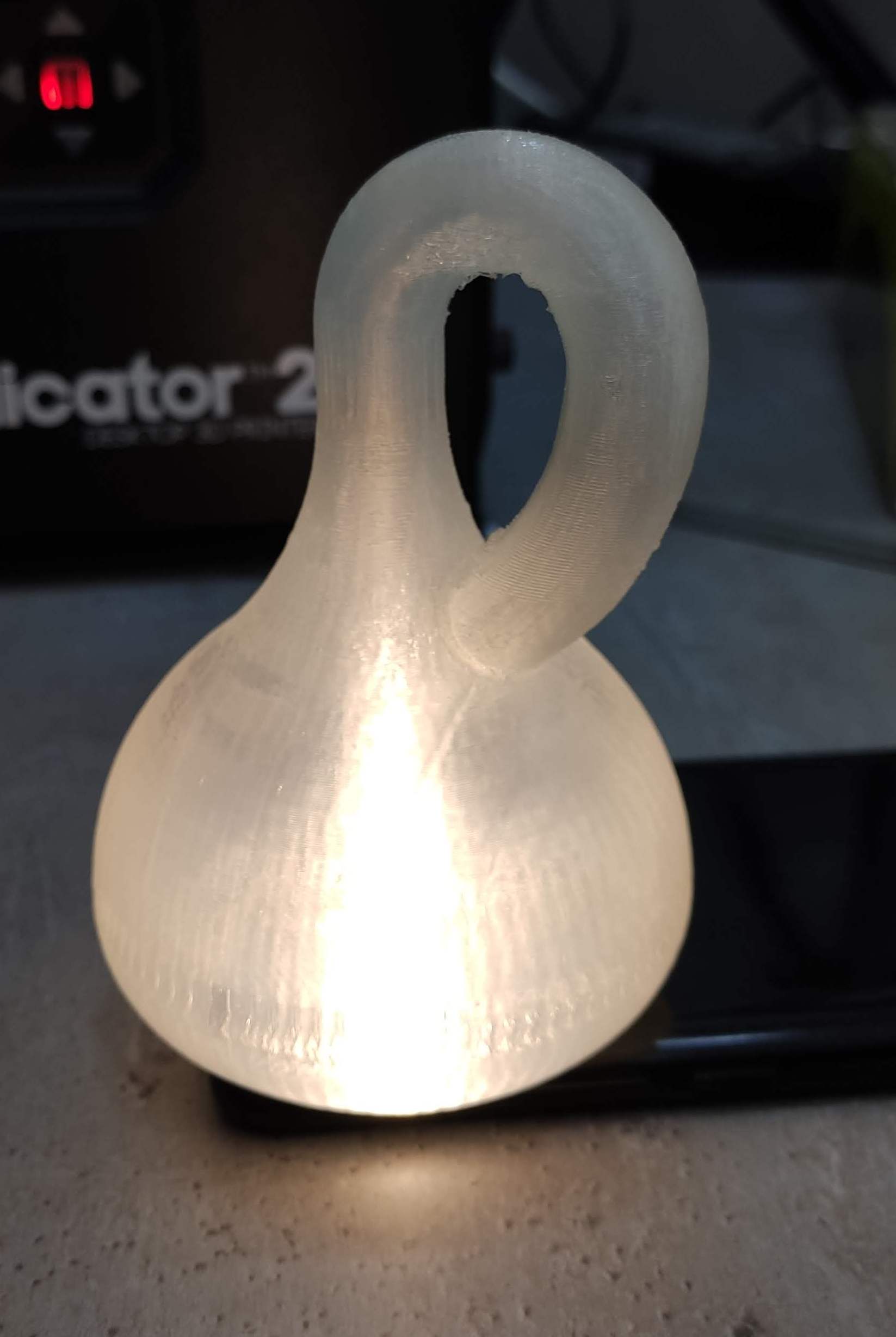
Isn't she a charm?
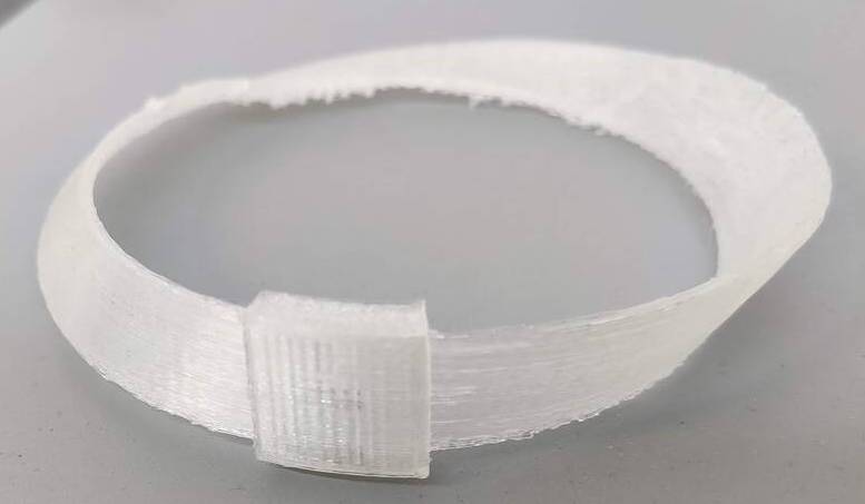
Printing a Möbius strip with a matador running around it
I had this idea of printing a transparent Möbius strip, with a sliding piece on top, and embossing a bull on the strip itself, and a matador on the sliding piece, so that the matador would have a chance to go around the strip once and arrive at the bull again as his own mirror image, not being able to fight the bull.
So where does the inspiration for that come from? The inspiration comes from my teenage years,
where my introduction to topology took place through two of my favorite human beings, two
personal heroes that I think have been widely underrecognized and under-appreciated:
mathematician (and mathemagician)
Martin Gardner and
physicist George Gamow.
Both had this genius of explaining complex subjects in a clear way accessible to the teenager I was back then.
I only had one book of George Gamow's: Mr. Tomkins inside Himself: Adventures in New Biology which he co-authored with the biologist Martynas Yčas back in 1968. The amount of fantasy in writing such a book is off the charts, and I am saddened that most kids today grow up without knowing such treasures exist.
Without further ado, here's the part from the book where he explains why...
It is not advisable for a matador to run around a Möbius surface
"Your engagement was broken!" exclaimed Mr. Tompkins. "But why?"
"Because," said Wilfred sadly, "I was too much involved in mathematical
problems and did not realize their possible biological consequences.
As I told you, I was working on problems of topology, particularly
on the Möbius twist, invented a century ago by the Swedish
mathematician Möbius."
"What is a Möbius twist, and how could it result in breaking up the
engagement of two young people who are in love?" asked his perplexed
father.
"Let me have a piece of paper, a pencil, scissors, and some glue,"
said Wilfred.
Though rather astonished by this request, Mr. Tompkins provided
the required materials. Taking the piece of paper, Wilfred cut from
it a ribbon a couple of inches wide and, twisting the ribbon a half-turn,
glued the ends together to form a ring.
"This is a Möbius ring," said he. "Unlike other rings, which have
two sides, an inner and an outer one, it has only one side. You cannot
paint this ring white on the inside and black on the outside or make
it of silver and gold-plate it on the outside, because it has only one side,
and if you begin painting it, starting from some point on either side,
and go all the way around, you will find that the entire ring becomes
the same color."
"I can understand, of course," said Mr. Tompkins, "that engagement
and wedding rings play an important role in marriage, but how could
a Möbius ring have broken your engagement to Vera, and put you in
the state you are in now?"
"It was all due to her father objecting to our marriage because I
could make no contribution to his shoemaking business. However,
one sleepless night it occurred to me that making right and left shoes
required two sets of machinery. Couldn't one make them all for the
left foot, let us say, and then turn one-half of them into right-foot shoes
by using some topological trick? This would surely reduce the cost
of production."
"But what has the Möbius twist to do with it?" asked Mr. Tompkins,
getting interested.
"Well, you see," said Wilfred, "if you go around the Möbius ring,
objects change their 'parity,' as the physicists put it today. Let me demonstrate
this using the twisted band I have just made for you."
He took out his fountain pen and sketched on the Möbius ribbon
a picture of a matador facing a bull, with a scarlet muleta and a sharp
sword in his hand.
"You know, of course," he said, "that a surface, according to Euclid,
has no thickness, so that drawings made on one side of it are just as
visible if one looks at them from the opposite side. It would be better
in this case to use transparent cellophane. As I have drawn it now, the
matador is facing the bull in the correct way and has every chance to
put his sword through the bull's heart. Now imagine that the matador
bypasses the bull and takes a run around the Möbius ring and returns
to the arena. When he returns to the original spot and faces the bull
again, he notices that he is standing on his head. This, of course, is no
way to fight a bull. But since the matador cannot leave his two-dimensional
surface, he must turn 180 degrees in the plane, in which case he
will have turned his back to the bull. Again not very convenient for
fighting the bull. Thus it is not advisable for a matador to run around
a Möbius surface!"
Mr. Tompkins was very much disturbed; his boy, who had always
been so bright before, now seemed to be talking nonsense.
"But what has all this to do with your break-up with Vera?" he asked.
"Oh, quite a lot," answered Wilfred. "You will have noticed that
after the matador has traveled around the Möbius twist, he has become
the mirror image of what he was before. Well, one sleepless night I
conceived the idea that the Möbius twist, well known in the case of
surfaces, could also exist in three-dimensional space. According to the
famous German mathematician Bernhard Riemann, who lived about
a century ago, three-dimensional space can be curved in the same
way as an ordinary two-dimensional surface. In fact, Einstein's entire
general theory of relativity is based on Riemann's geometry. If there
are Möbius twists in two-dimensional surface geometry, as I have just
demonstrated to you with this paper strip, there should also be similar
twists in three-dimensional space which turn objects traveling around
their vertices from right-handed modifications to left-handed ones. Also
I remembered reading that a biological expedition to the upper region
of the Amazon River had found two kinds of snails, whose
shells were mirror images of each other. Could it be that there is a
Möbius twist axis crossing the surface of the earth somewhere down
there? There, the two kinds of snails might have been originally identical,
but could have become mirror images of one another because
some of them had migrated around the Möbius vortex.
"If this were true, one should be able to turn left-handed gloves,
shoes, and automobiles manufactured in Great Britain into their
right-handed replicas merely by sending them around the Möbius
vortex.
"The next morning I appeared at Mr. Sapojnikoff's factory, and after
two hours' waiting was admitted to his luxurious office, where six
telephones sat on his otherwise empty, ping-pong-table-sized desk.
" 'Have a cigar,' said he. 'It is a real Havana—Castro or no Castro.
What have you to say?'
" 'Sir,' said I, 'I suppose that you are aware of the fact that each
man as well as each woman has two feet: a right one and a left one.'
" 'So what?' asked Mr. Sapojnikoff, taken by surprise.
" 'Doesn't it make the production of shoes more expensive because
two different sets of machinery are required to manufacture right and
left shoes?' I asked. 'Wouldn't it be simpler if one could produce shoes
for only the right foot or the left?'
" 'And let all the people jump on only one foot, or what?' grumbled
Mr. Sapojnikoff, now persuaded that I—the candidate for his daughter's
hand—was really nuts.
--From Mr. Tompkins inside Himself: Adventures in New Biology by George Gamow and
Martynas Yčas (1968), pp. 67-70.
Back to creating the strip
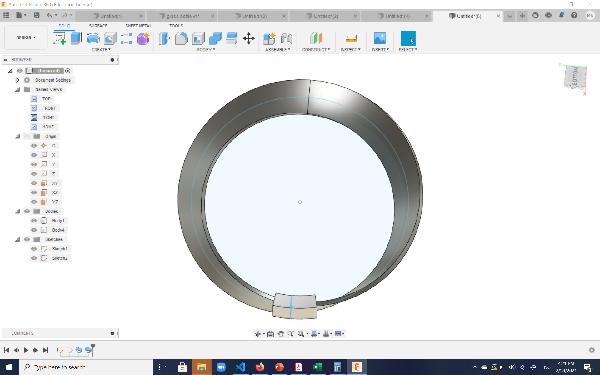
I designed the Möbius strip using Fusion 360, and ran into some problems during which I consulted this video which was helpful.
The design was accomplished by sweeping a rectangle surface along a circle. The hardest part to make sure it was a rectangle and not a paddec cube, and secondly, that the path went straight through the middle of the rectangle, so that when twisting 180° along the sweep, the edges of the rectangle would end up touching.
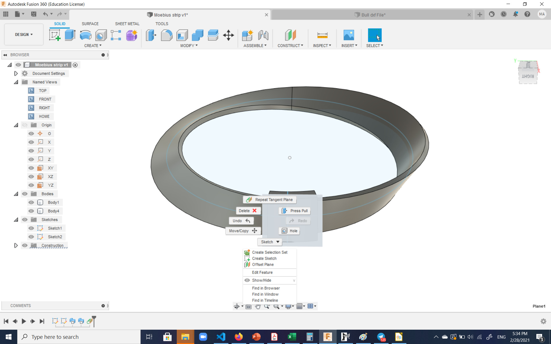
After designing the strip itself, I tried to build the sliding part adding two rectangular offsets in the sketch of the strip, and then partially sweeping them:
Here a possible problem would be that considering the curve of the slider and the curve of the Möbius strip itself, and the fact that the PLA implementation would be a hard body, the slider might run into some problems sliding around it. For the beginning though, I left a 1 mm margin from each side between the slider and the strip.
Next I wanted to emboss the image of the matador on the slider and the bull on the strip itself, to show case what happens when the matador goes around the strip half-way until he arrives to the bull, whom he can now not face face-to face. Since drawing those in Fusion 360 were quite challenging, I downloaded the following dxf files from the internet to import to Fusion 360 and emboss. However, trying to import just the bull image froze the Fusion software, and I had to close the program.
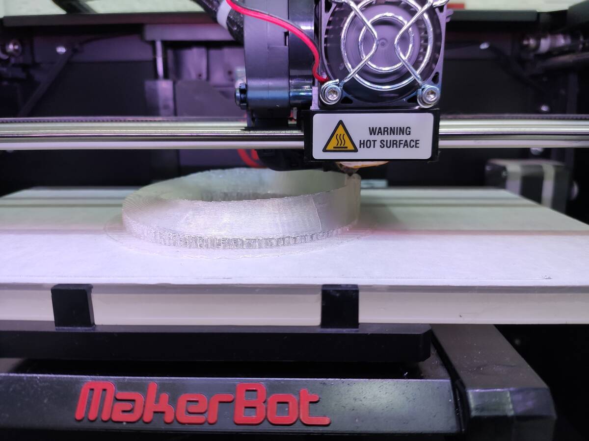
Before trying the embossing again, I decided to print the strip and the slider using transparent PLA, and see what can be achieved. The transparent PLA at the lab is older and has possibly absorbed some humidity and is a bit brittle, so not the best PLA available to print, but for this experiment, it was important that I tried the transparent one.
I set the number of shells to 3 and set out to print, with a 0.22 layer height to give it a bit of speed. The program created lots of support, which was due to the slider touch the z origin which had made the rest of the strip hang in the air. This was the result:
I tried to remove all the support and the raft using my hands, which was unsuccessful and led to breaking the strip, and then used two pliers, which were mostly succesful. The bottom part was still rough at many points. The slider, unfortunately, was stuck and could not slide. Improvements will have to be done to the design before attempting a second print.
As for improvements, I'd probably need to increase the distance between the strip and the slider. But that may not be enough, as I'll need some sort of minimal support between the two. So the slide probably has to be on the lower platform, where the rest of the strip will have to resting on further supports. If the slider does happen to detach but can't slide on the strip, I'll probably need to scale up the strip (but not lengthen the slider) so that the straight slider can easily slide over the curved of the strip.
Photogrammetry
I had a few attempts at 3D scanning. I decided to take photographs and use Meshroom to perform photogrammetry to attach them together.
Initially, I took photos of my son with my phone and tried that, but due to the fact that he could not stay still, the results were not very good.
Then I decided to take photos of a child's foot taken by Joseph by a Canon camera for creating orthotics and try photogrammetry on them. The result was as follows:
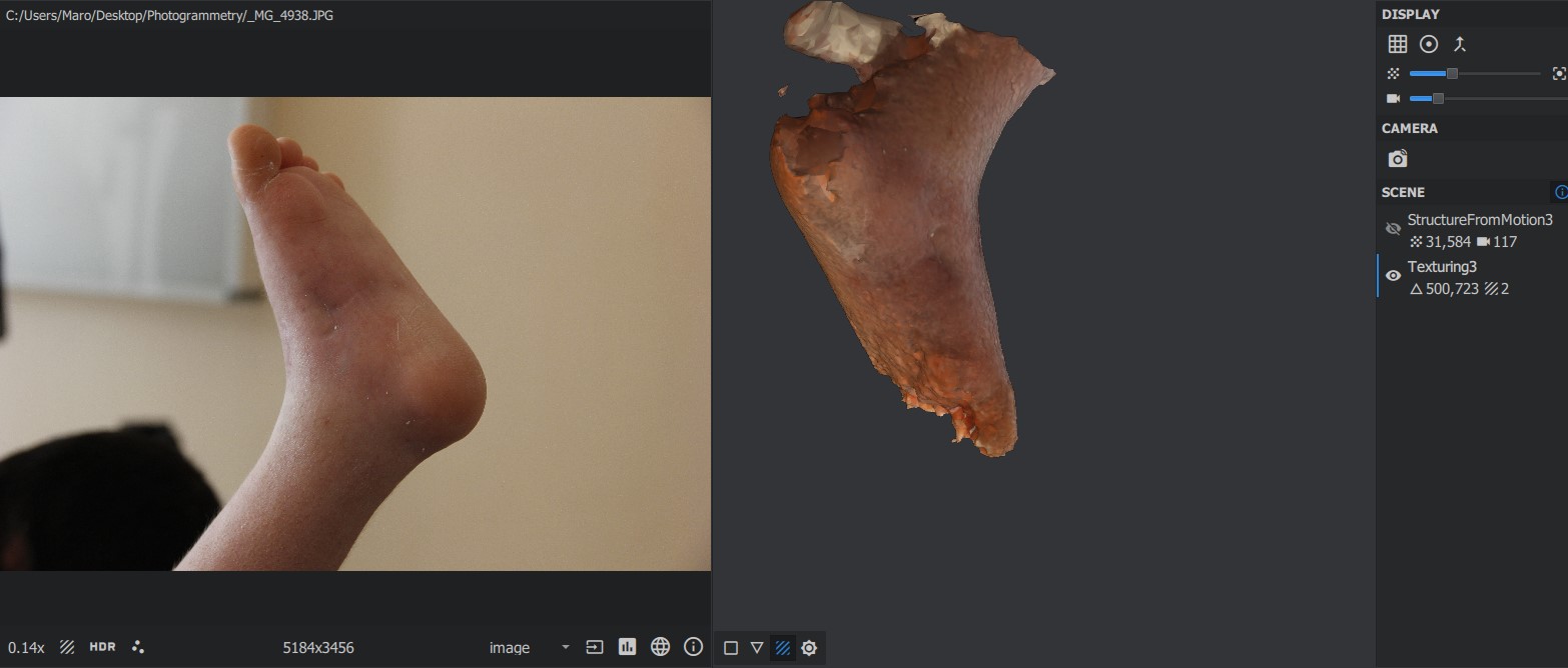
The resulting 3D file is included below.
Later in the course, I had access to the Artec Eva 3D scanner through the Oqni organization. Thanks to the organization making the device available, I was able to 3D scan arms and legs.
For an example of a successful 3D scanning of an arm which was completed later, please checkout the scanning section in the Wildcard week assignment.
Downloading the files
The files for this week can be downloaded here:

