Computer-controlled machining
For this week, we had to design something 'big'. And for the group assignment part, we had to do the lab's safety training and test runout, alignment, speeds, feeds, materials, and toolpaths for our machine. The group assignment can be found at the corresponding page.
Ideas for what to design
First, I had to come up with what to design. I worked on three different ideas as described below. Children's slide was my favorite by far; however, did not meet the lab's requirement to use one plywood sheet per student. The infinity cube was quite intriguing, but with 1.6 cm maximum thickness of plywood, might not have been quite feasible. So I ended up designing a deer-hear clothes' hanger.
A children's slide
Safety of a slide
I tried to find some information regarding what angles of a slide are safe. Per the Michihan State Handbook for Public Playground Safety the following design criteria are recommended to make a slide safe:
- For a free-standing slide, the recommended length of the platform to facilitate going from a standing to a sitting position is at least 56 cm (22 inches).
- The platform should be horizontal and have a width at least equal to the width of the slide.
- Guardrails or protective barriers should surround a slide platform.
- handholds should beprovided at the entrance to all slides to facilitate the transition from standing to sitting and decrease the riskof falls. These should extend high enough to providehand support for the largest child in a standing position, and low enough to provide hand support for the smallestchild in a sitting position.
- At the entrance to the chute there should be a means tochannel a user into a sitting position. This may be a guardrail, a hood, or other device. Whatever means is provided, it should be of a design that does not encourage climbing.
- Slides should not have any spaces or gaps between the platform and the start of the slide chute.
- It is recommended that the average incline of a slide chute be no more than 30 degrees. No span on the slide chute should have a slope greater than 50 degrees
- Straight slides with flat open chutes should have sides with a 10 cm (4 inch) minimum height extending along both sides of the chute for the entire length of the inclined sliding surface.
- The sides should be an integral part of the chute, without any gaps between the sides and the sliding surface.
- The exit region should be essentially horizontal and parallel to the ground and have a minimum length of 28 cm (11 inches).
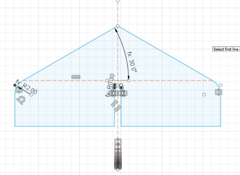
The design
I went as far as designing the slide chute and the side guardrail before finding out that we could only use one sheet of plywood and the slide would at best require two. The design of the platform, the platform guiderails, the hood to guide the child to sit, the stairs and extra base plank remain to be completed.

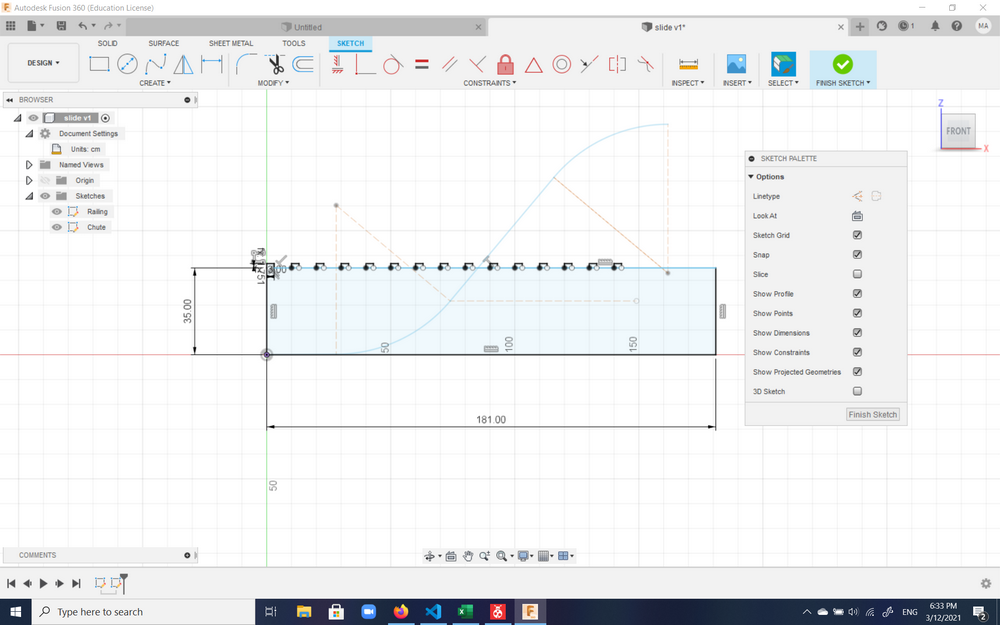
The design was of course parametric with the following parameters:
As I moved on to other designs, this remains as something I'll complete in my spare time at some point.
The infinity cube
Another idea to try was the infinity cube. In this case, two of the dimensions have to be equal and the tricky part it to design such joints that will function in rotation of 90 degrees around one axis as well as another by cutting in one direction only (without rotating the plywood). As the thickest plywood sheet to be used was 1.7 cm and the mill to be used was 6 mm, it was questionable whether in case of T-bone joints the remaining 5 mm (2.5 mm from each side) of the joint would be enough to keep the wood together, as well as how flimsy would a structure of ~70 cm length be with sides that are 1.7 cm thick. So this idea was forgone for the next, though I might try to create it at a smaller scale just to experiment with the joints (an interesting geometry thinking game).
An important rule of thumb in case of our 6 mm end bit to keep in mind is that the components being cut should be at least 1 cm away from each other and 3 cm from the sides.
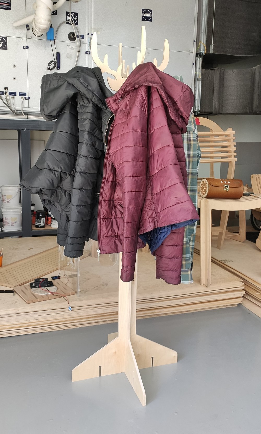
The deer hanger
The design
This was the final idea settled upon. It is a simple clothes hanger with a head resembling a deer portrait.
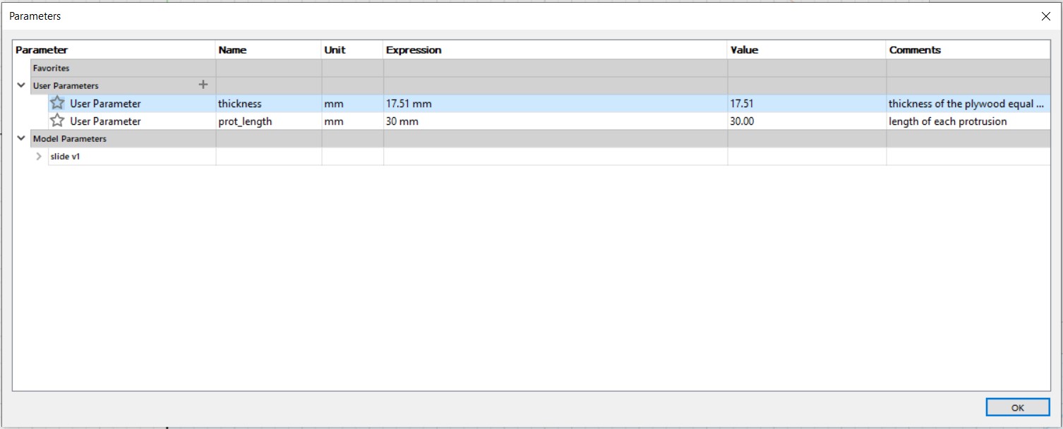
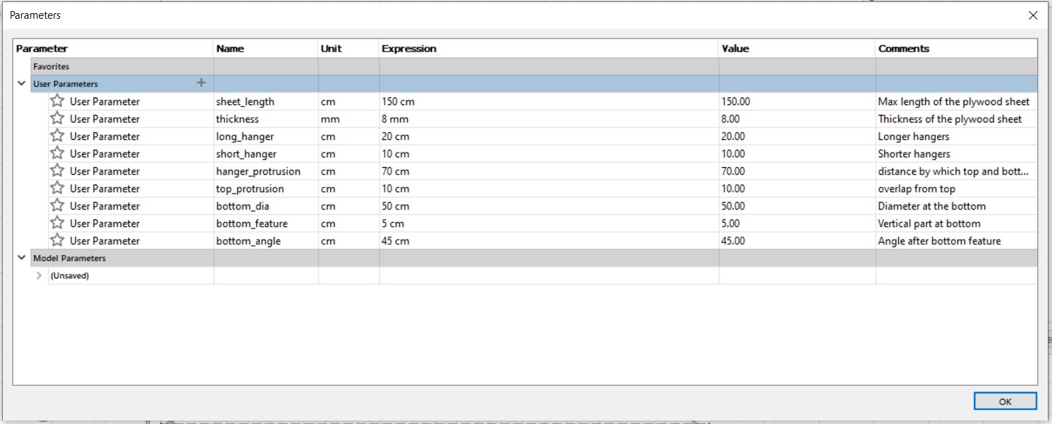
The bottom part of the hanger was designed first. The design was parametric with the following parameters:
Then a deer head had to be fixed to the top.
This .stl file
was downloaded from the internet, opened in Fusion 360 from File -> Open...
and since it was a meshing body, sketch of half the outline was traced using Fit Point Spline and the next half
generated through the Mirror function.
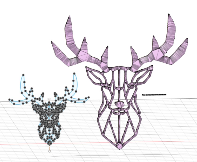
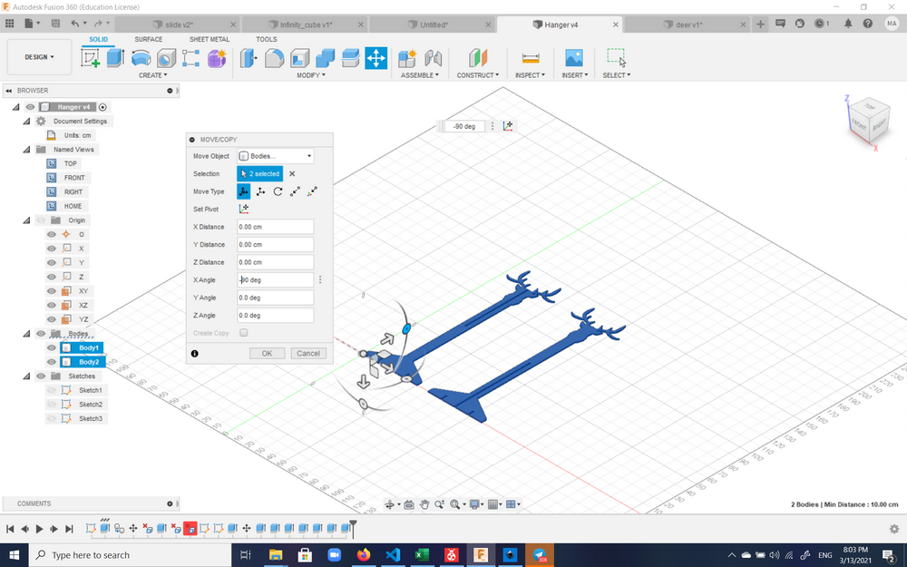
The sketch was then resized and copied into the hanger design file.
The rest of the hanger was designed. For stabilizing the bottom part, four stabilizers were designed.
Here the final sketch can be seen:
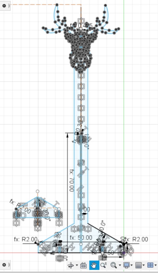
And the final design including the tolerance comb was generated:
Generating the .sbp file
The CNC machine to be used in the Dilijan Fab Lab is a ShopBot.
In order to cut there, either a g-code or .sbp file can be used.
Fusion 360 allows direct generation
of the .sbp file through its Post Process function.
In order to prepare the file to be printed, first of all the Workspace was changed from
Design to Manufacture.
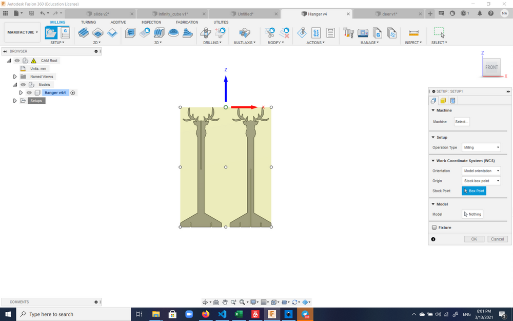
Then a new setup was created. This can be done either by right-clicking on Setups from the
Browser and selecting New Setup or from clicking Setup under Milling.
Here the stock size where it would be milled would be configured. The workable area of ShopBot was 1.2x1.5 m, while the size of a whole sheet of plywood was 1.5x1.5 m. Plywood sizes varied with 1.6 cm being the thickest.
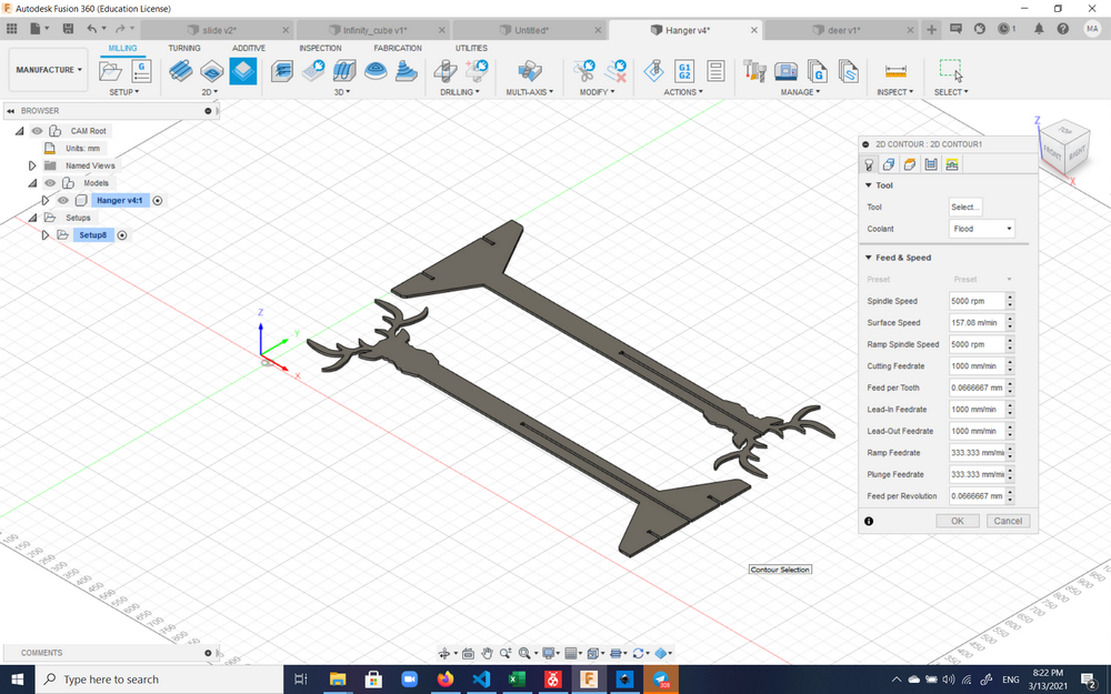
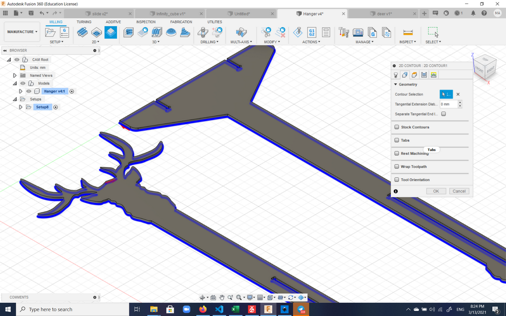
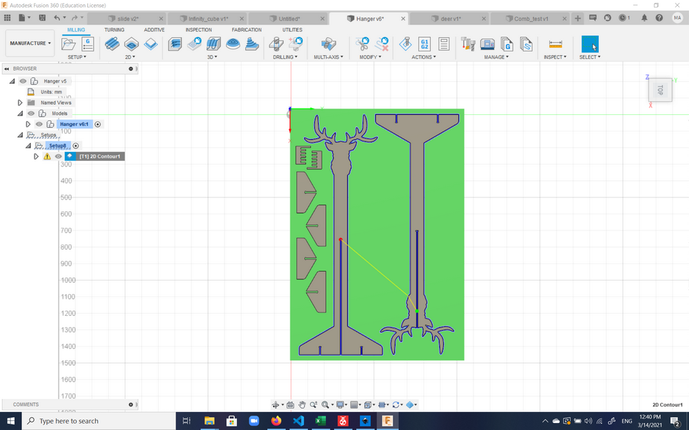
After the setup, a milling process would have to be defined, and in this case 2D contour was
chosen as the hanger would only be cut all around and groves or motion of the mill in the 3rd dimension (up and down)
would not be needed.
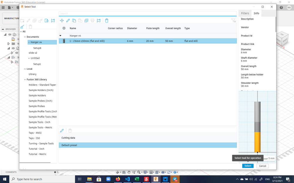
For this process, the correct tool bit had to be selected. In this case that would be a flat end mill:
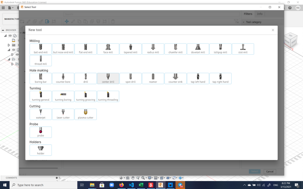
Then the characteristics (diameter, length, etc.) of the flat end mill had to be specified. Here the diameter and number of flutes are important to specify. The other characteristics are not as important if the mill is being changed manually.
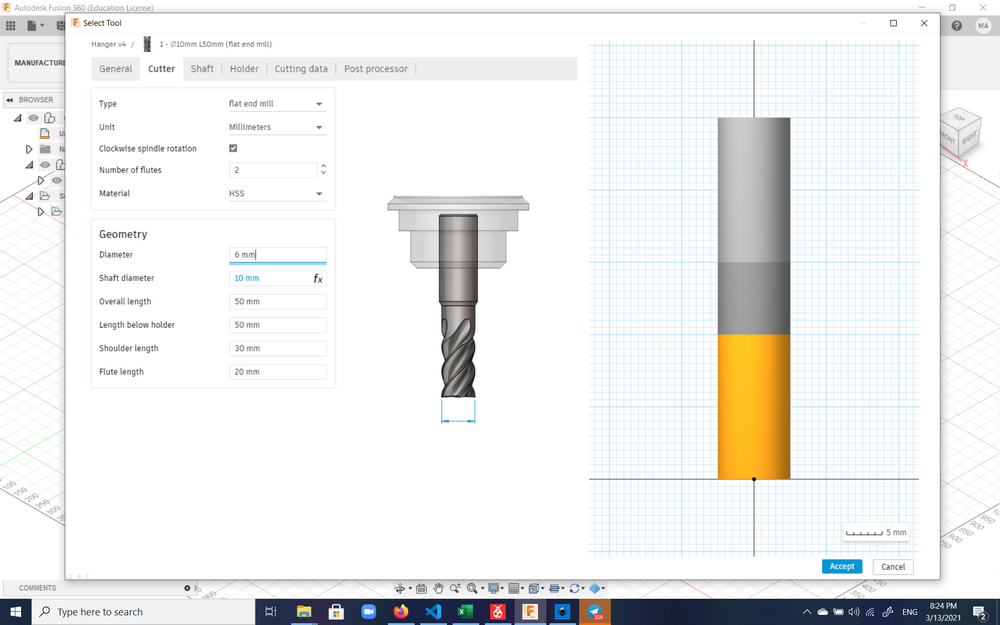
The defined tool would then have to be selected:
Then the bottom contours of the objects to be milled had to be selected to set up the process:
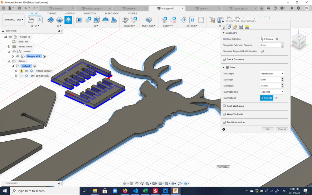
Now, in order for the plywood sheet to remain where it was and not to move, precautions had to be taken. One such precaution was to screw parts of the board that were not part of the hanger to the board. Another thing that could be used, especially for smaller pieces such as the stabilizers where screwing them in could ruin the aesthetic, was to use 'tabs'. Tabs are thin sections of the plywood that are left unmilled/uncut, and can later be broken off manually and filed/sanded. Fusion 360 provides the option of selecting the location of the tabs on the contour manually.
Then cutting could be simulated using the Simulate button/command.
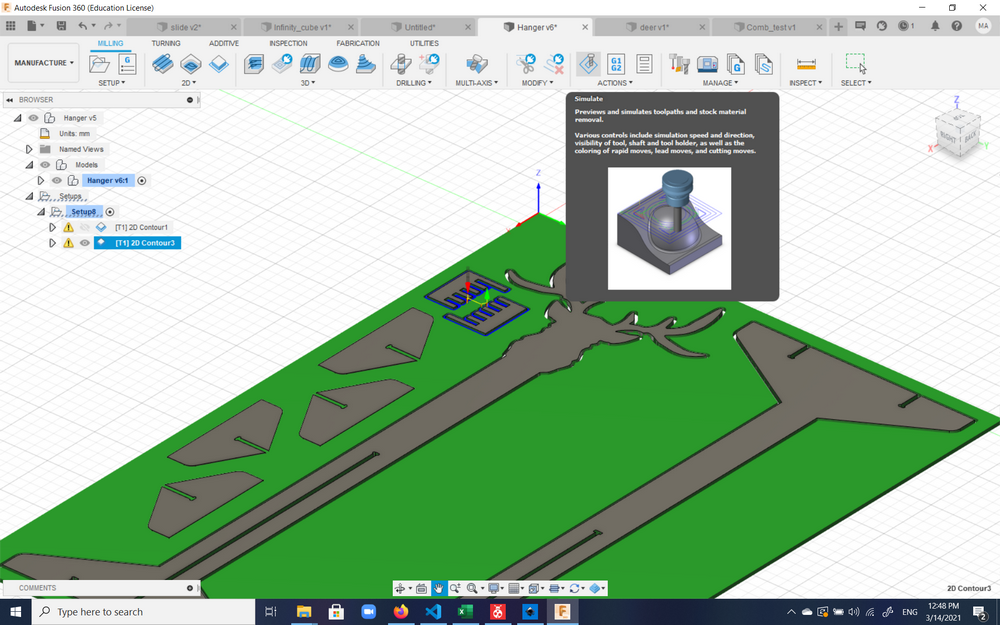
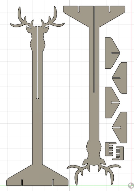
The pieces of the hanger were nested near each other as much as possible to cut down on the amount of plywood used and keep it reusable as much as possible.
The .sbp file could now be saved and transfered to the computer connected to the ShopBot to be milled. ShopBot of course comes with its own software which can open the .sbp file and work with it.
Preparation for milling
Fab Lab Dilijan uses a ShopBot for Computer Numerical Control machining purposes.
Before milling with the machine, it is of utmost importance to familiarize oneself with the ShopBot User's Manual, especially the safety section. Before beginning, one should take note that there is an emergency stop button located at the computer desk of the CNC machine:
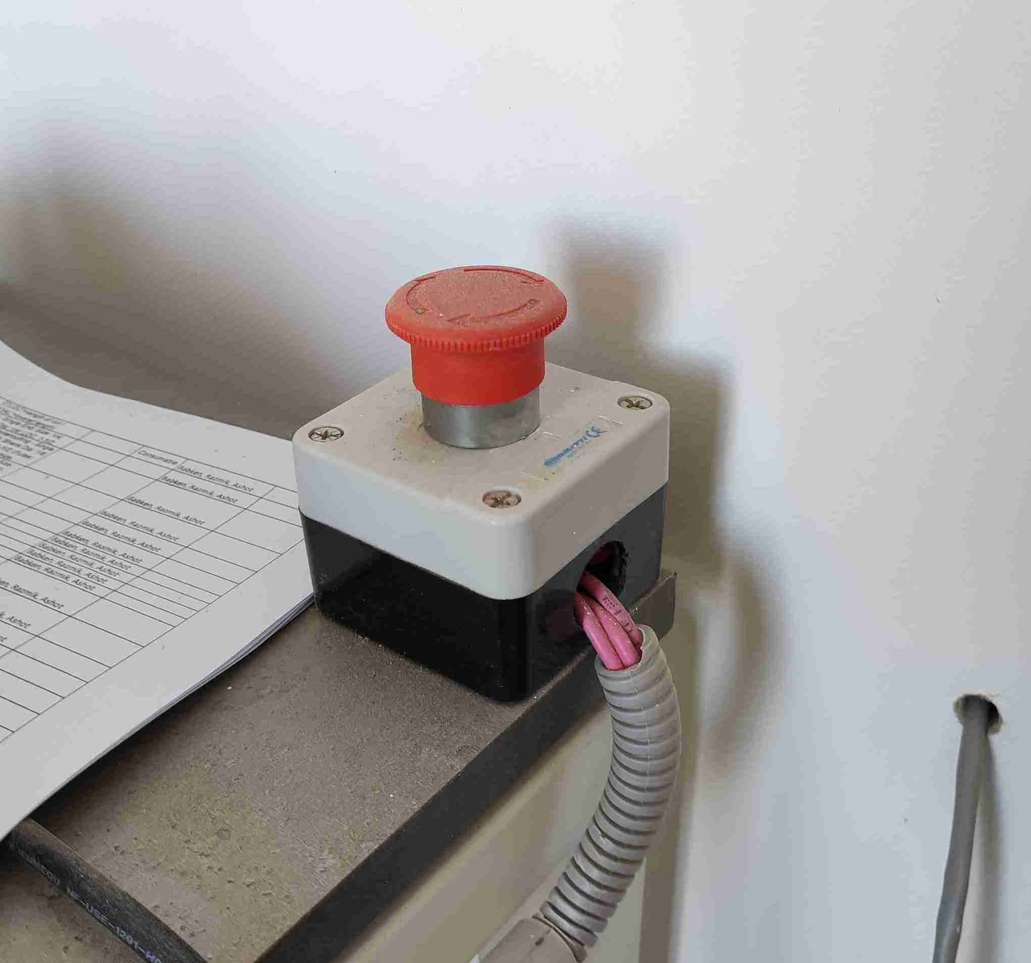
which will stop the machine by cutting off the supplied electricity to the machine and the area around, including the spindle, dust collector, and computer connected to the machine. There is a similar button outside of the CNC room in the main Fab Lab area which serves the same puspose. There are other soft and hard means to stop the machine which will be discussed in the Turning on the ShopBot section.
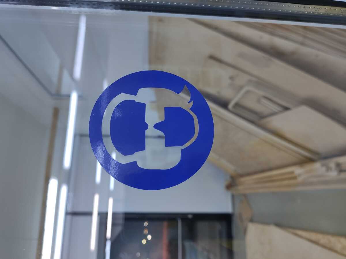
Eye and ear protection must be worn at all times when the machine is operating. Most of the noise is generated by the dust collector, but if something goes wrong, there may be even higher decibels of noise that the ears must be protected against. Also, in case an incident happsn and a piece of wood or broken mill flies off, eyes should be protected. Personally, I prefer to use a face mask as well to avoid breathing in the dust. In case of plywood, the dust is non-toxic. Though in case of OSB or MDF the dust might include adhesives or resin binders as well.
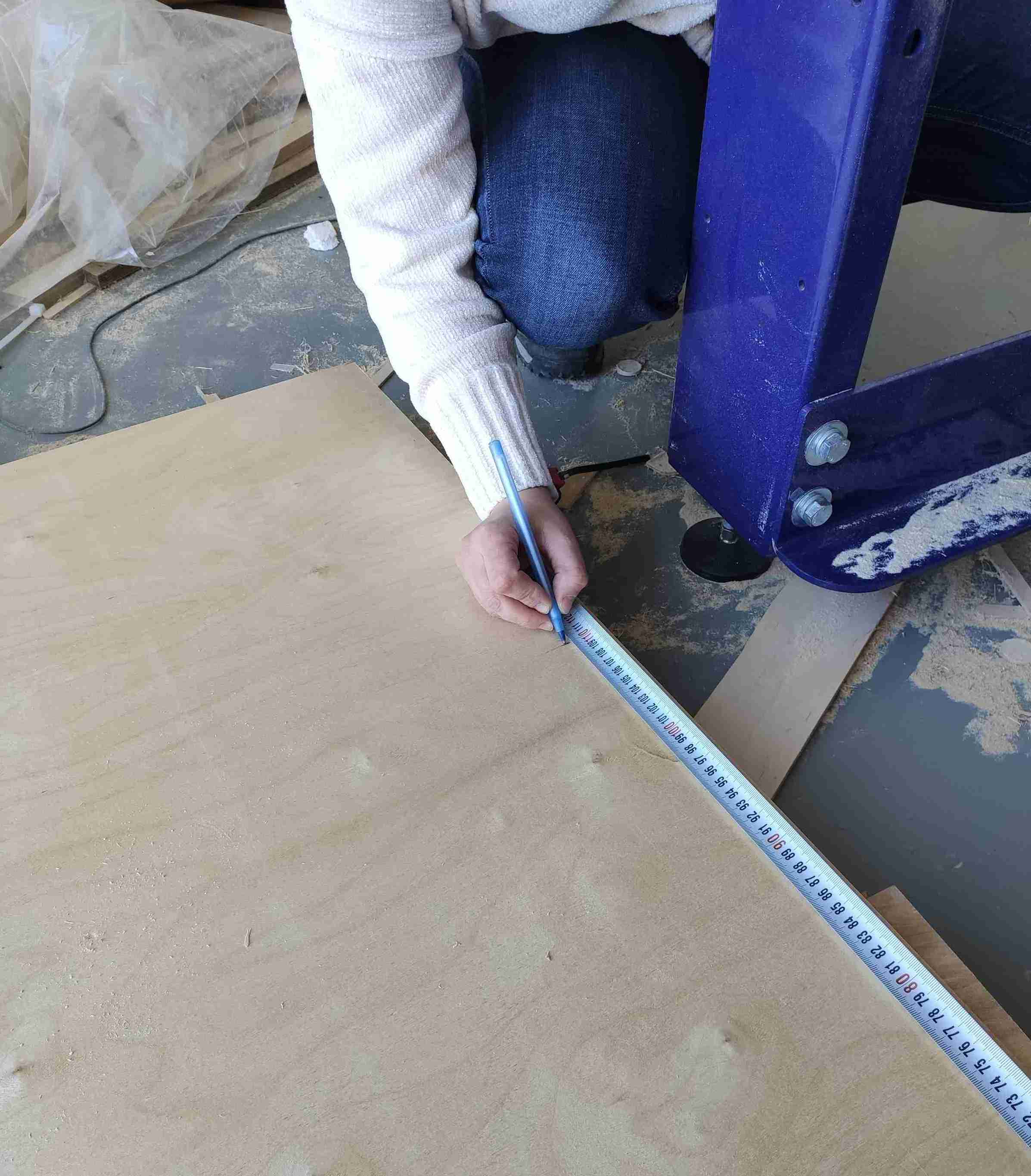
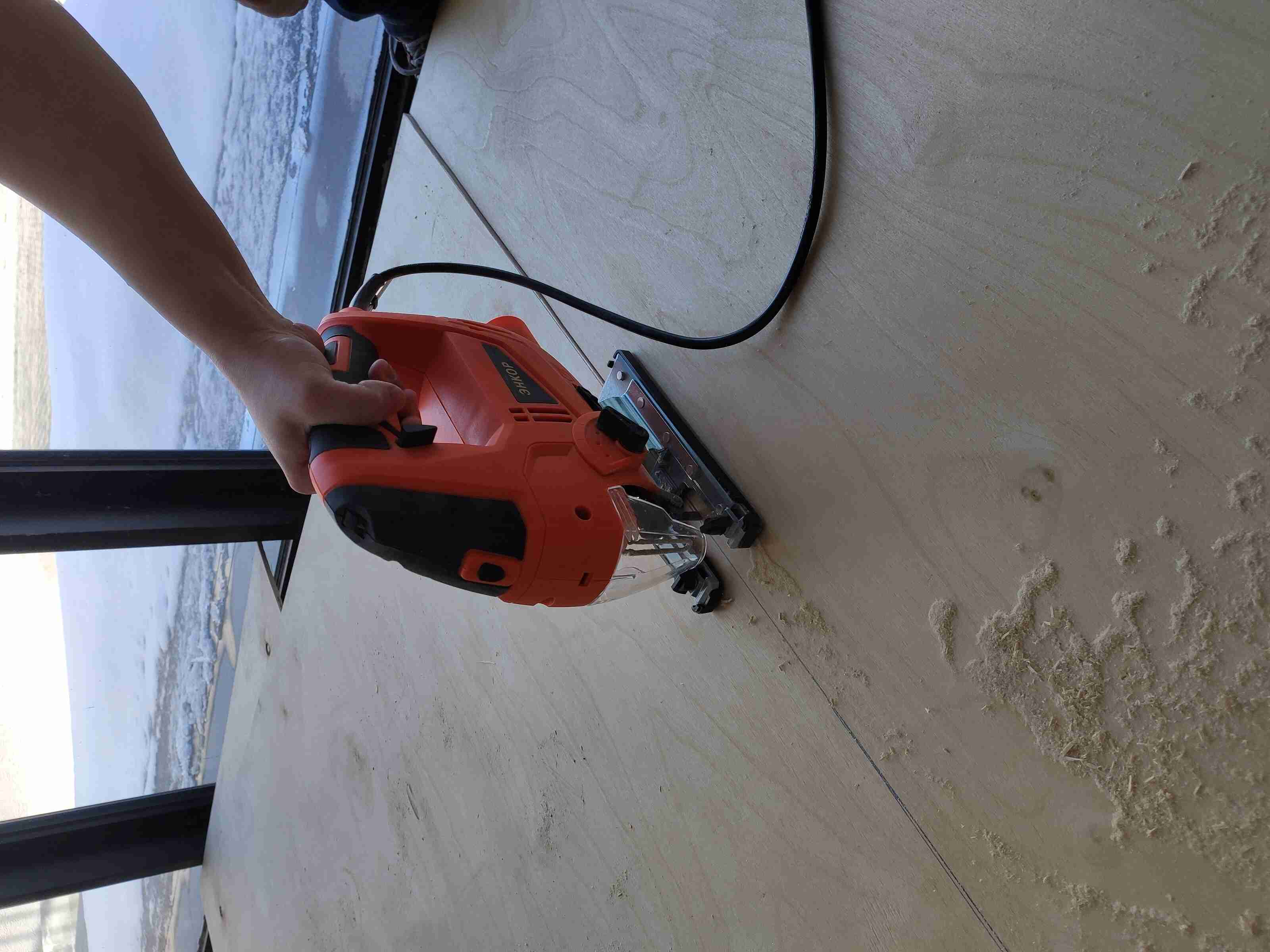
The plywood sheets available at the lab had dimensions of 1.52 m x 1.52 m, but the working area of ShopBot was 1.52 m x 1.20 m, which means the board had to be cut before being placed on the ShopBot surface. Before cutting, a 1.20 m distance was measured along one of the dimensions of a 10 mm-thick plywood sheet; it was a bonus to take the grain direction into account per our instructor Ashot's suggestion. The distance was then marked with a pen:
The cutting itself was accomplished using an Enkor jigsaw:
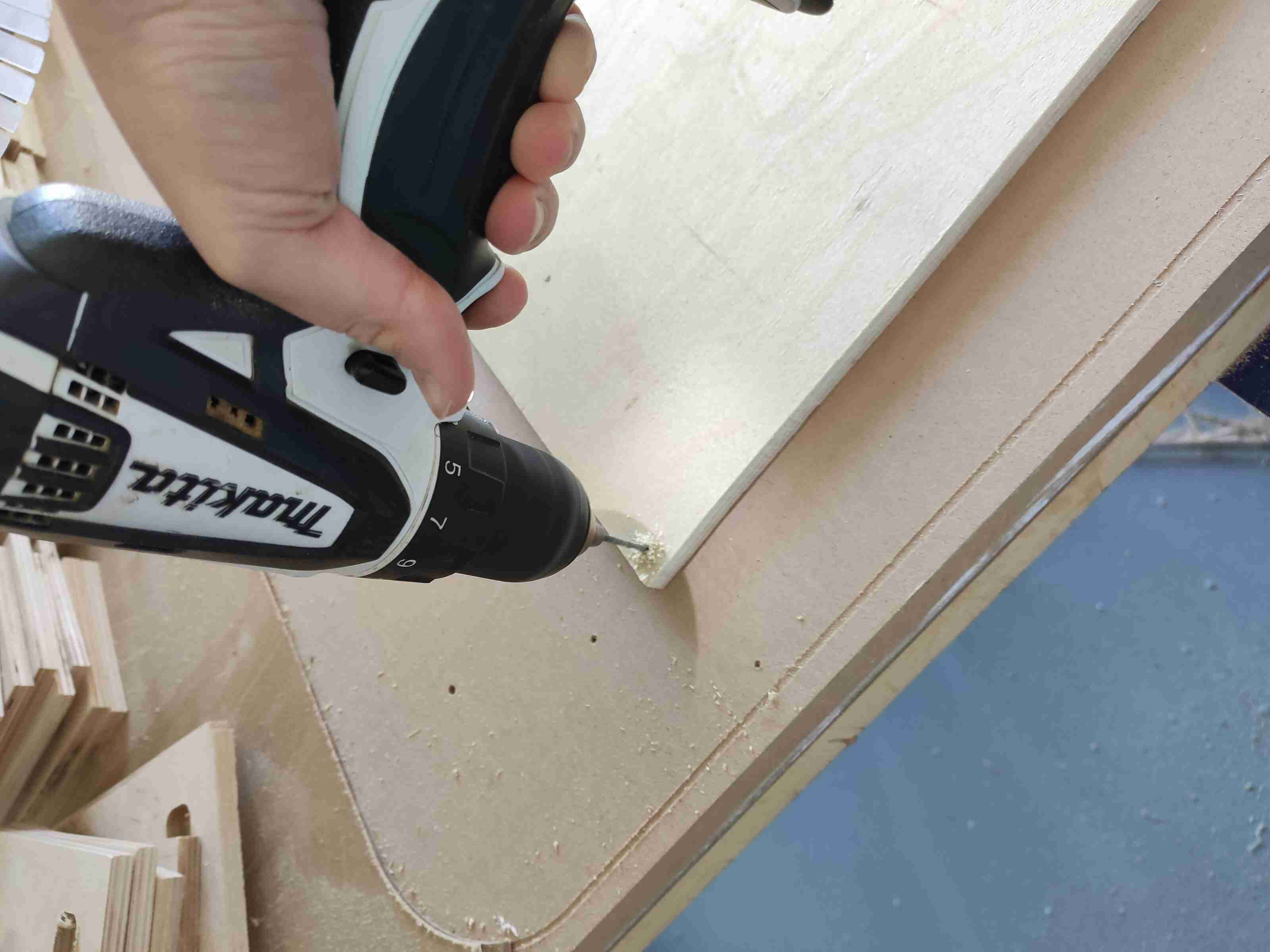
The plywood sheet was then placed on the ShopBot board with help from our instructors. In order to secure the sheet so that it wouldn't move during the milling process, screws were placed in the corners of the board. The design itself had left a 3 mm marginal distance so as to not mill over the screws. Before screwing in the sheet, holes were placed in their location using a hand drill:
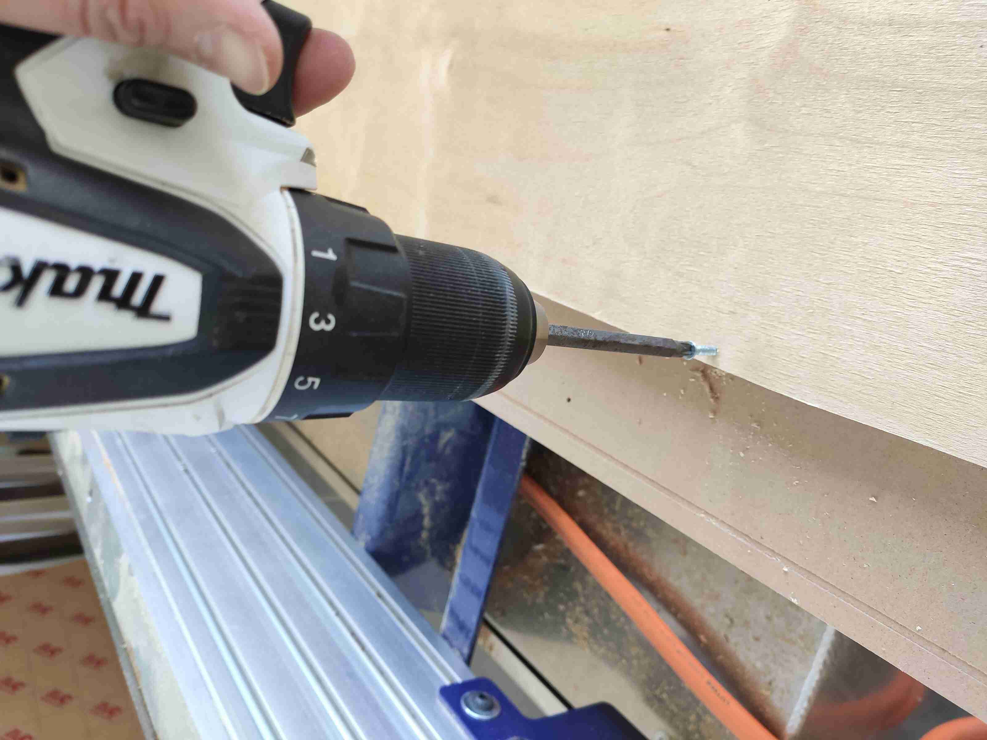
And then screws were inserted using the same drill driver with a screwdriver bit:
Now on to placing tool bits on the machine: There are various sizes, shapes, and types of bits that can be used on the machine. The extensive bible of machining to be consulted is Machinery's Handbook.
Three general types of bits can be specified:
- Drill bits: These cut vertically, but not horizontally.
- Mill bits or end mills: These mill horizontally and vertically.
- Router bits: These mill horizontally, but not vertically.
Each bit comes with various number of flutes. Fewer flutes take bigger bites and remove material better. More flutes are better for a nicer finish. Furthermore, flutes can meet in the middle, which means the tool can move vertically or horizontally, or they can be distanced in the middle, which means they are better at chip cleaning, but can't go down as much.
Many bits come with various color coatings (e.g. ceramic, carbide, etc.) meant to enhance their strength, lifetime, or other properties.
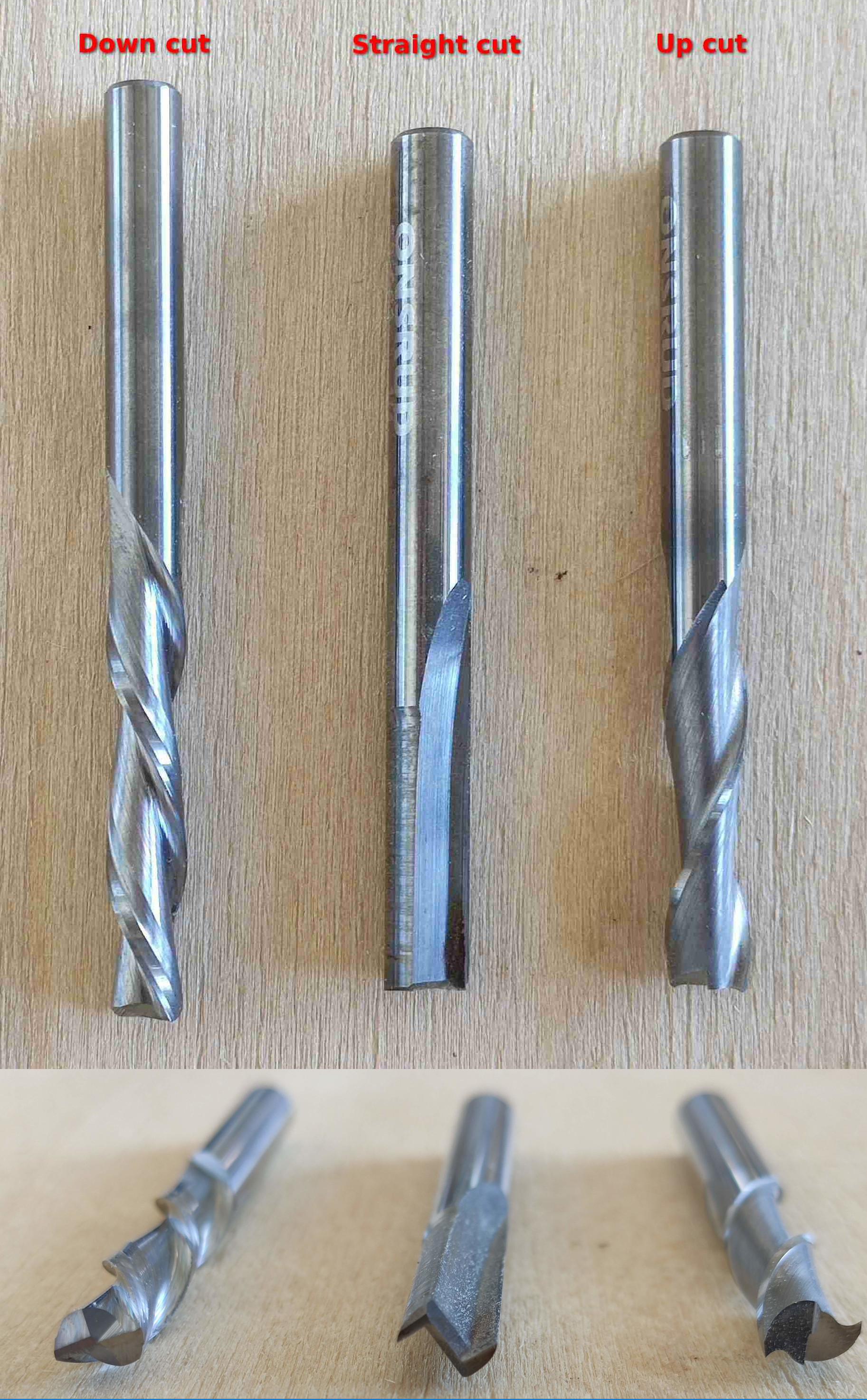
Four types of end mills can also be categorized based on the direction of their spirals, which affect how the milled material moves afterwards:
- Up-cut bit: The spirals of this bit move the material up when rotated clockwise. They don't leave a clean top surface, but a clearn bottom surface, and remove material easily.
- Down-cut bit: The spirals fo this but move the material down when rotated clockwise. They leave a cleaner top edge, but can compress material down as they do and heat up.
- Straight-cut bits: The flutes on these are parallel to the ground.
- Compression bits: These have both up-cut and down-cut spirals meeting the middle of the tool, which means they do a nice job on the top and bottom surface, but keep compressing the milled material in the middle.
Here's a useful video comparing the different bits and how they cut:
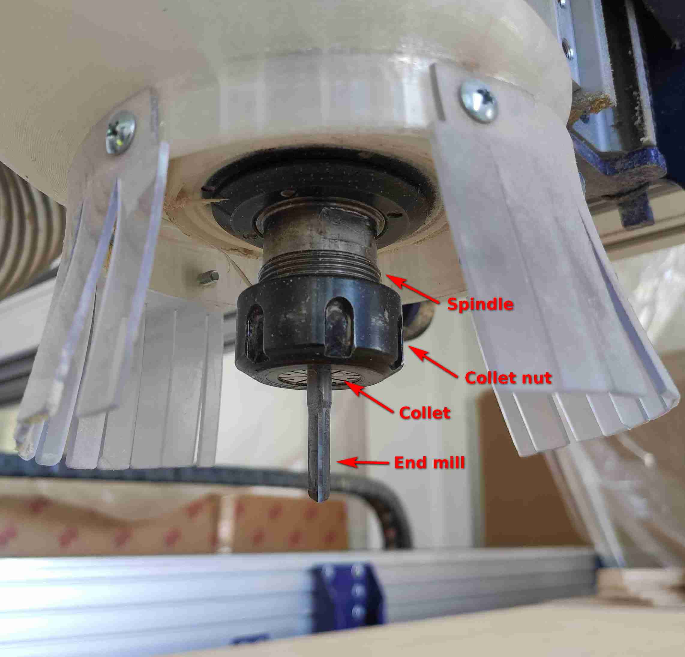
The bit used for milling in a ShopBot sits inside a collet, which is then compressed with a collet nut to hold the bit tightly against the spindle, which has a motor to rotate it, effectivly rotating the bit and milling the board.
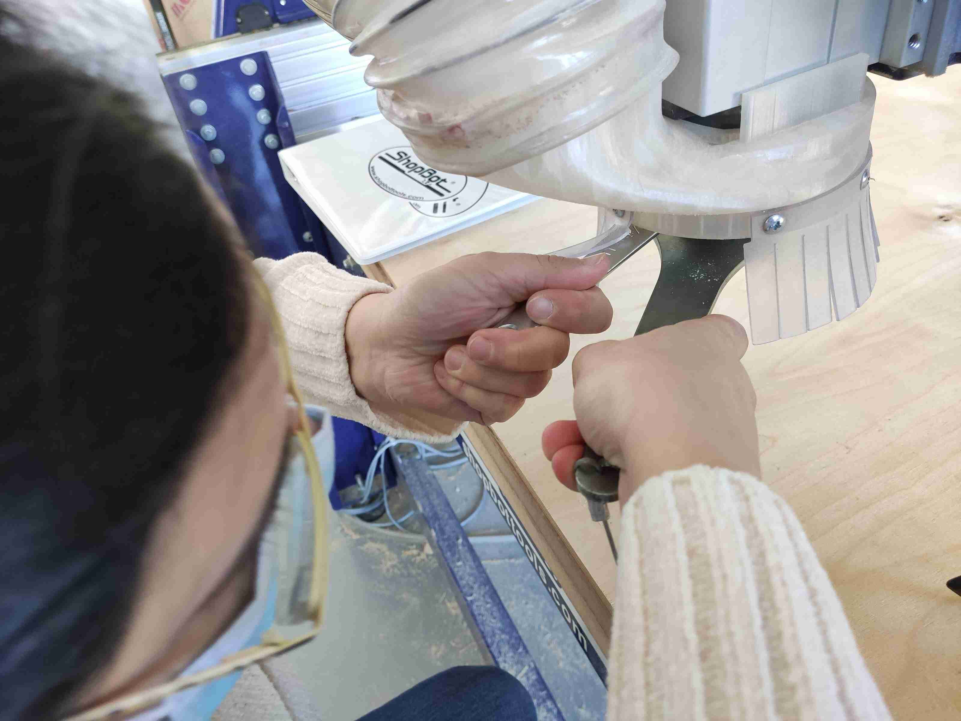
In order to change the bit in the collet, ShopBot and especially the spindle have to be turned off. In order to ensure that, there's a nice safety feature that comes with ShopBot: the wrench needed to remove the collet nut is attached to a wire attached to a key that disengages the spindle. So if you're going to use the wrench, you *have* to turn off the spindle. The arrangement can be seen below:
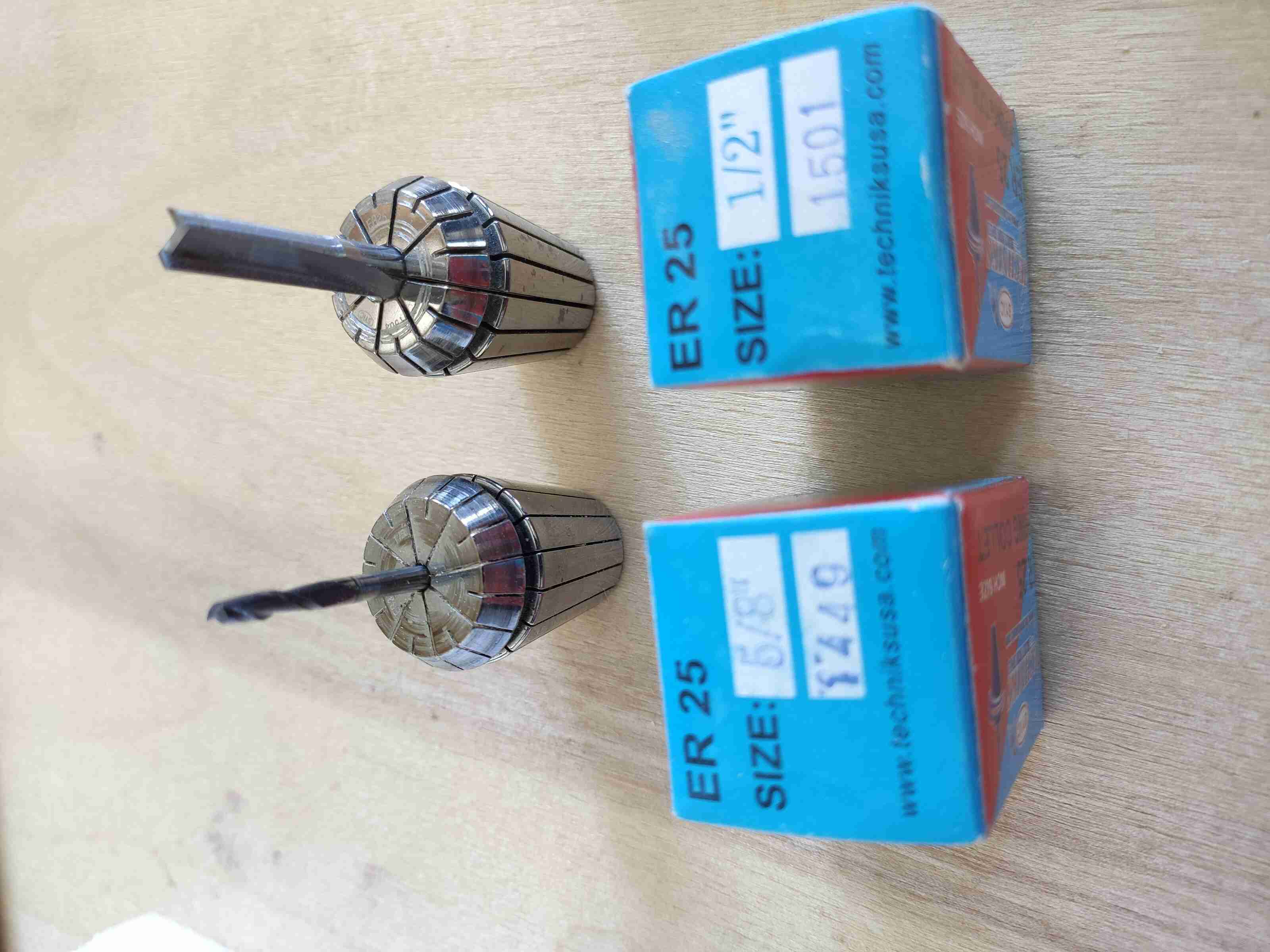
After disengaging the spindle key, the wrench was removed and itself and a hex key were used in conjunction to loosen the collet and replae the mill bit that would be used, a 6 mm straight cut end mill in this case:
The end mill outer diameter must correspond to inner colet diameter for maximum hold, maximizing colet's life, and reducing vibration.
Turning on the ShopBot
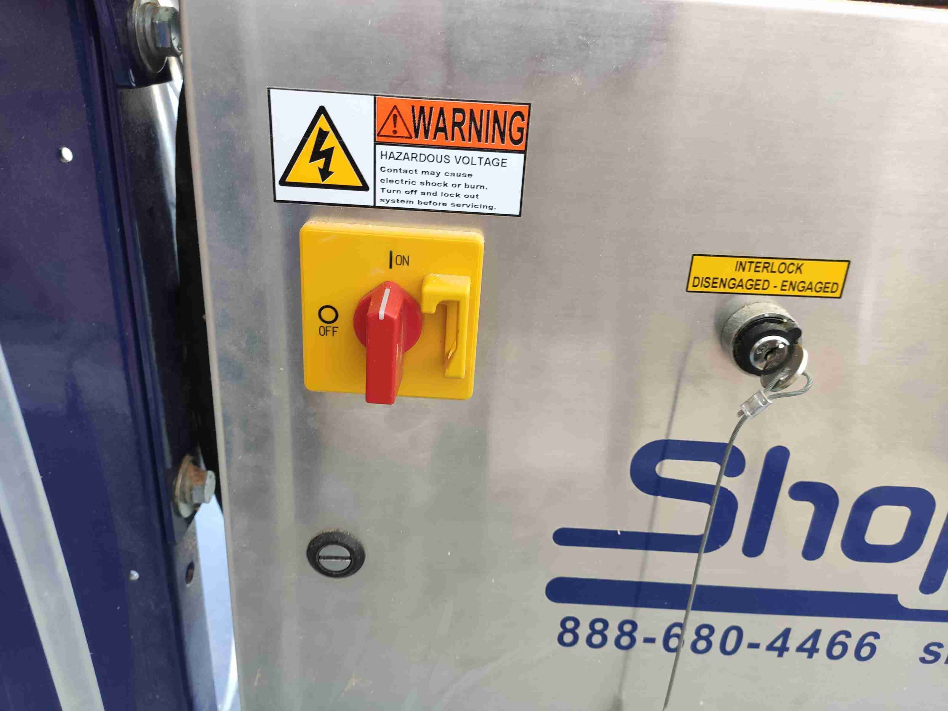
In order to turn on the machine, four steps should be followed: 1. Turn on the switch for ShopBot and make sure the spindle key is engaged:
Once the spindle is turned on, you can see it on the spindle case. You don't need to touch the default settings:

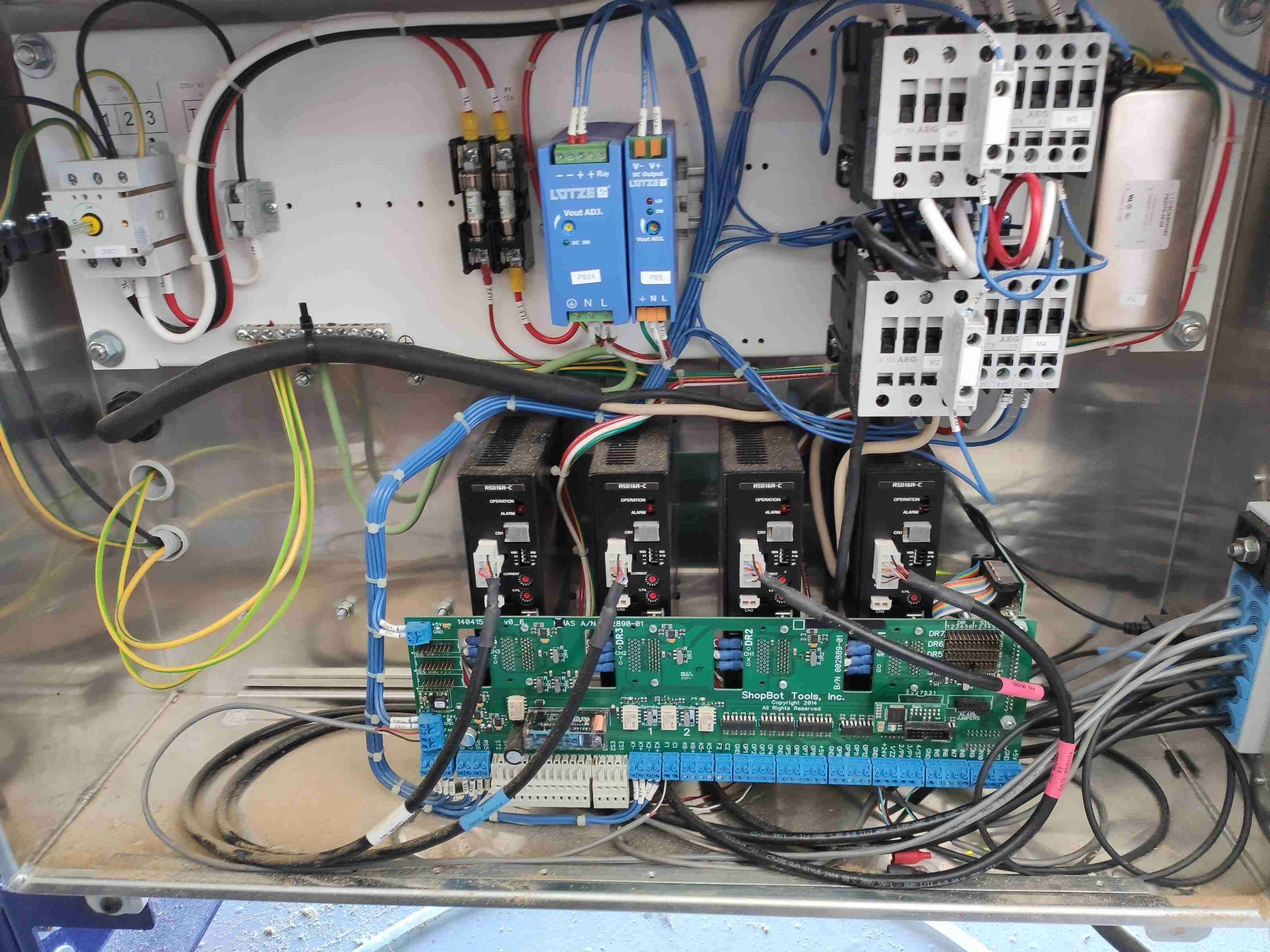
And here's what lies inside the case of the spindle controller -- the guts. Hopefully, touching that will not ever be needed unless for the pusposes of enhancement:
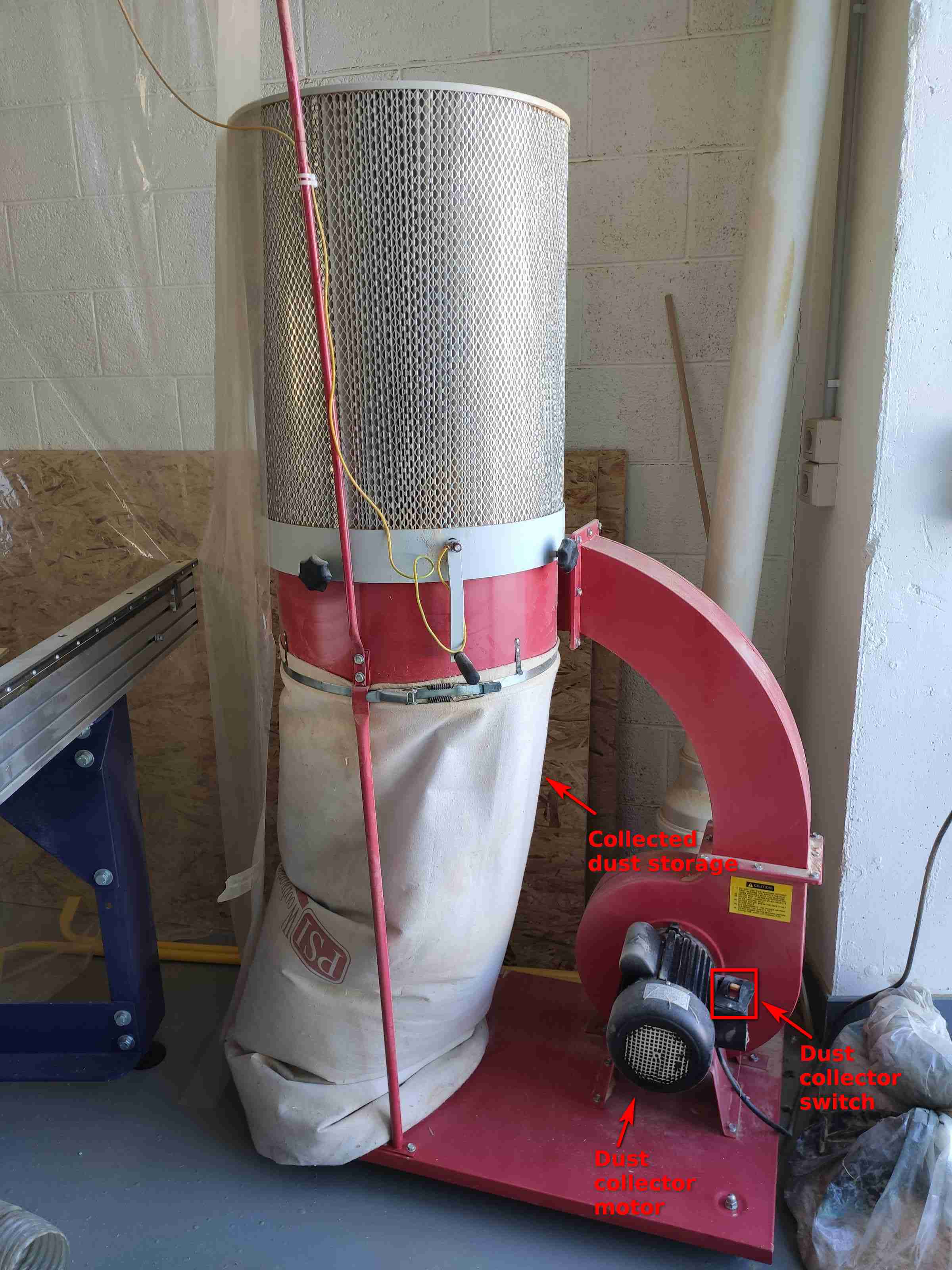
2. Turn on the dust collector:
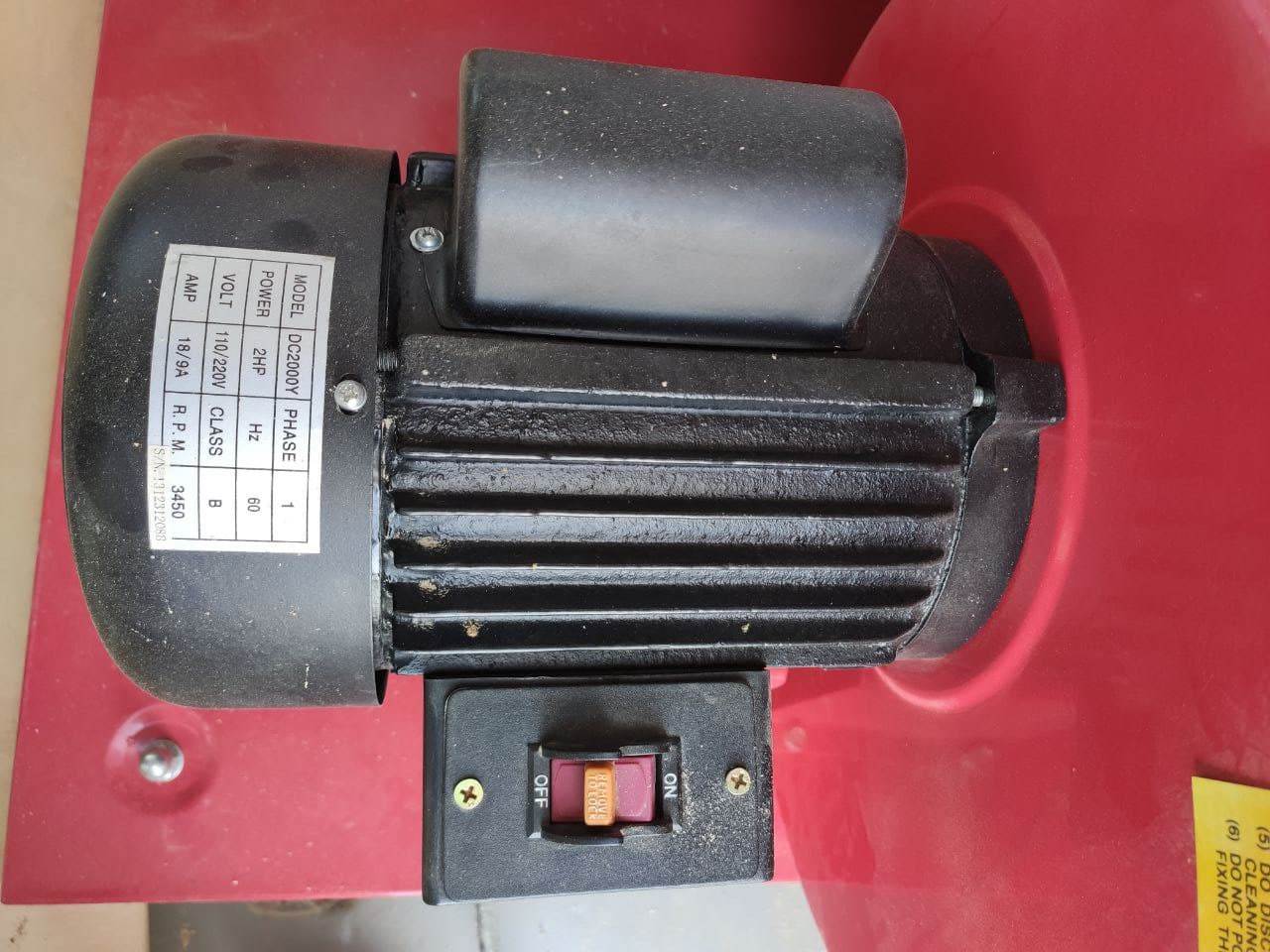
This turns on the dust collector to take care of all the dust generated during the milling:
3. After turning on the machine and the dust collector, before being able to cut, Reset has to be selected from the ShopBot set of buttons:
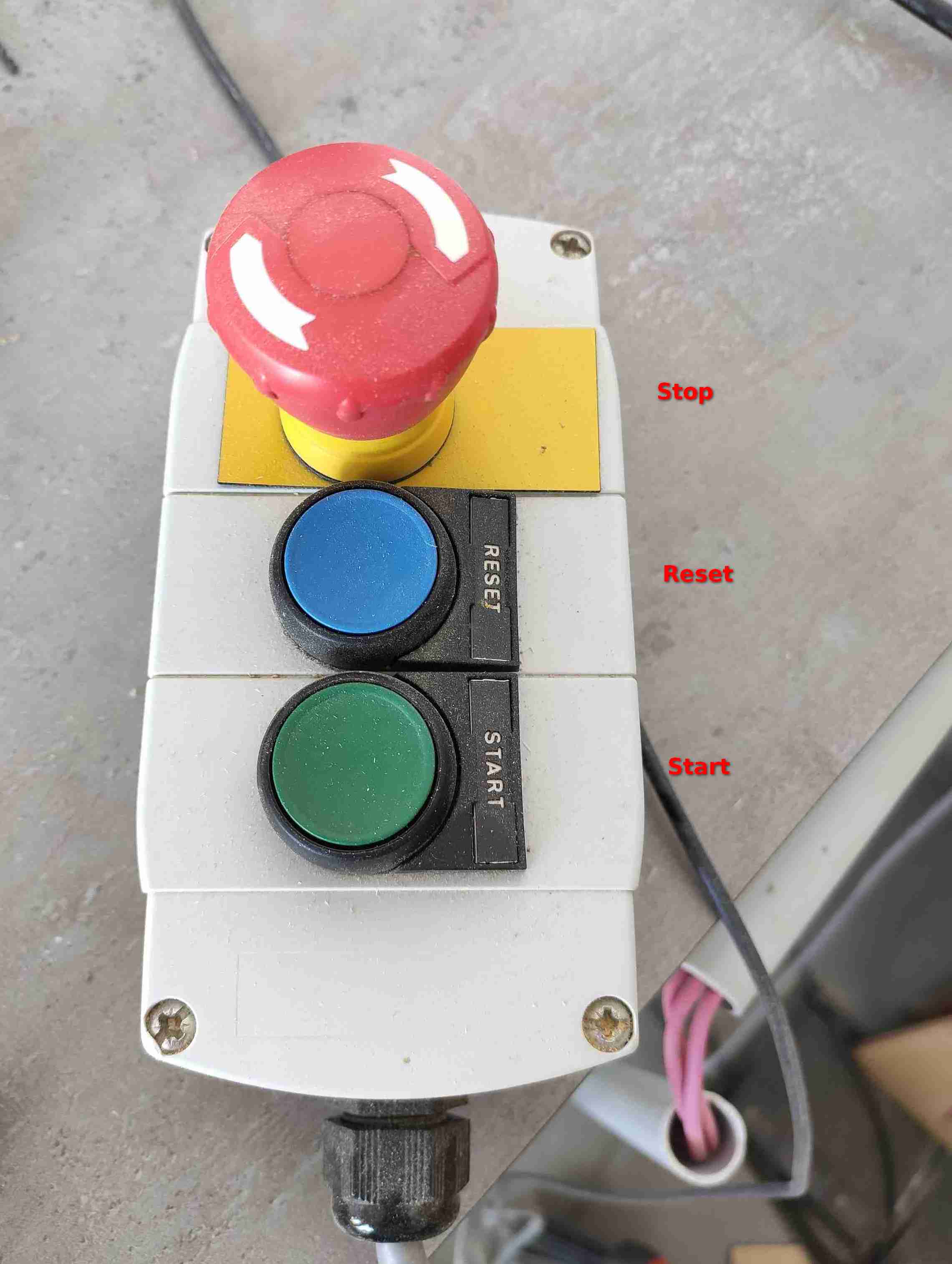
4. Once the cutting program (e.g. .sbp) is loaded into the computer and cut has been selected, Start button has to pressed for the machine to start actual milling.
Zeroing the axes
In order to zero the axes, the ShopBot software was turned on. The spindle was moved to the right bottom edge of the table to set the x and y axes.
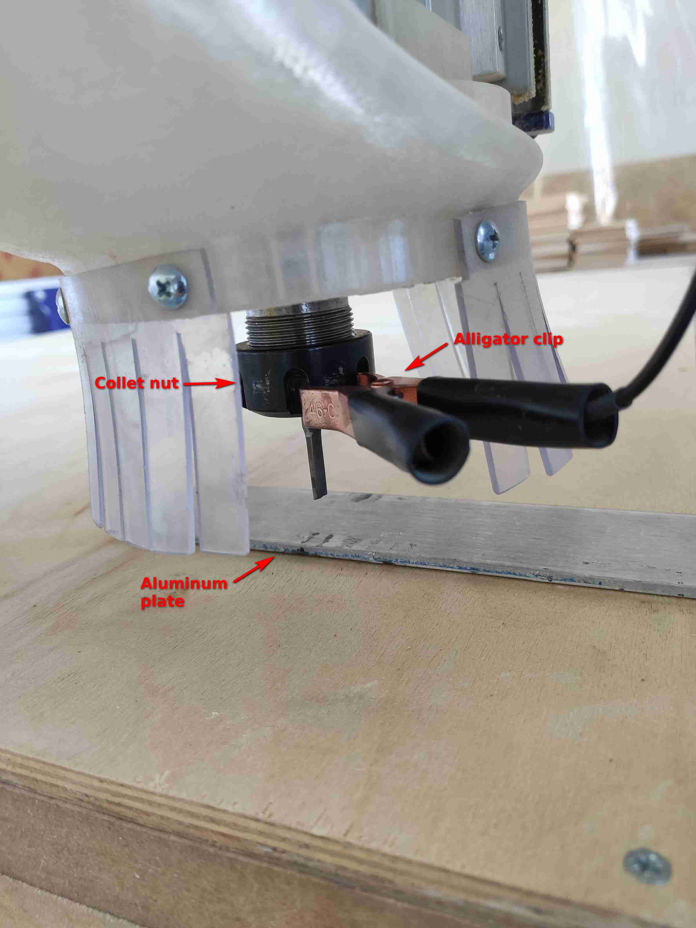
For the z axis, a conductive anode and cathode were used. An alligator clip is set on the collet nut, and an aluminum plate is placed underneath the bit. The software is then asked to zero the z as a result of which it gently lowers the spindle, and once an electrical connection is established between the plate and the bottom of end mill, the program automatically zeroes the z.
The spindle should be raised then before beginning the milling.
Milling with ShopBot
Once the machine is turned on and the .sbp file loaded into the ShopBot software, the milling may begin.
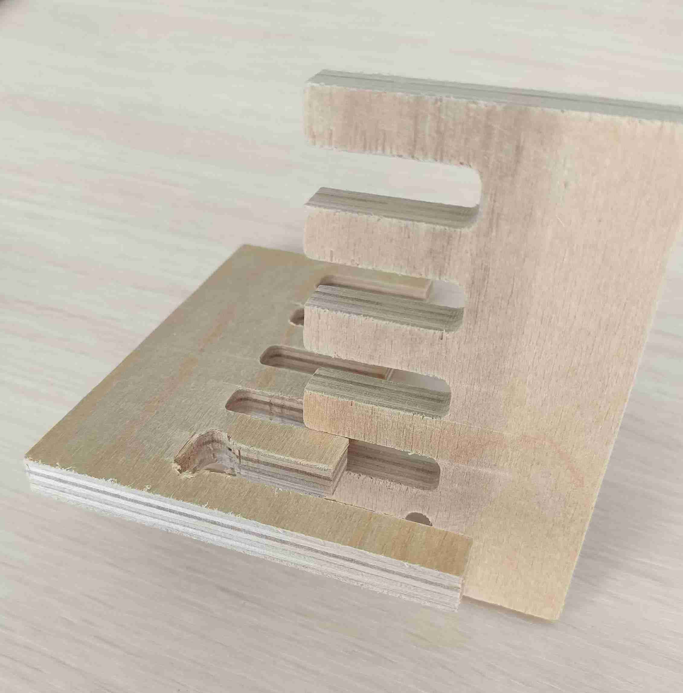
For the group assignment, a comb was created to test the fitting of parts with various widths. A complete account of the group assignment can be read at the group assignment page.
Then the CNC machine was set to cut the hanger.

After breaking the tabs and getting the pieces out, an attempt at assembling the hanger was performed without sanding the fitting section. The piece didn't go all the way in, as could be expected:
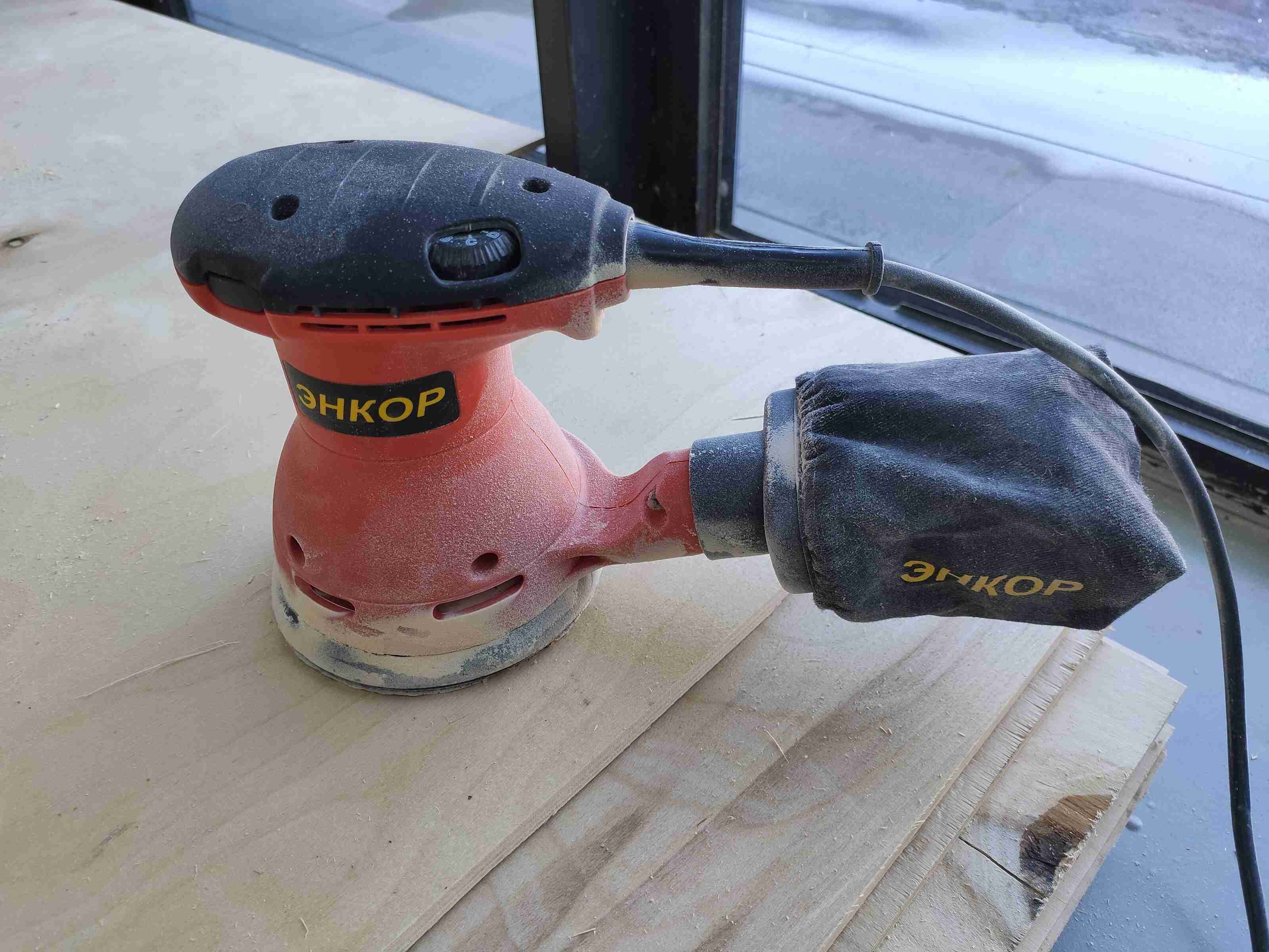
The edges of the hanger were then sanding quite a bit:
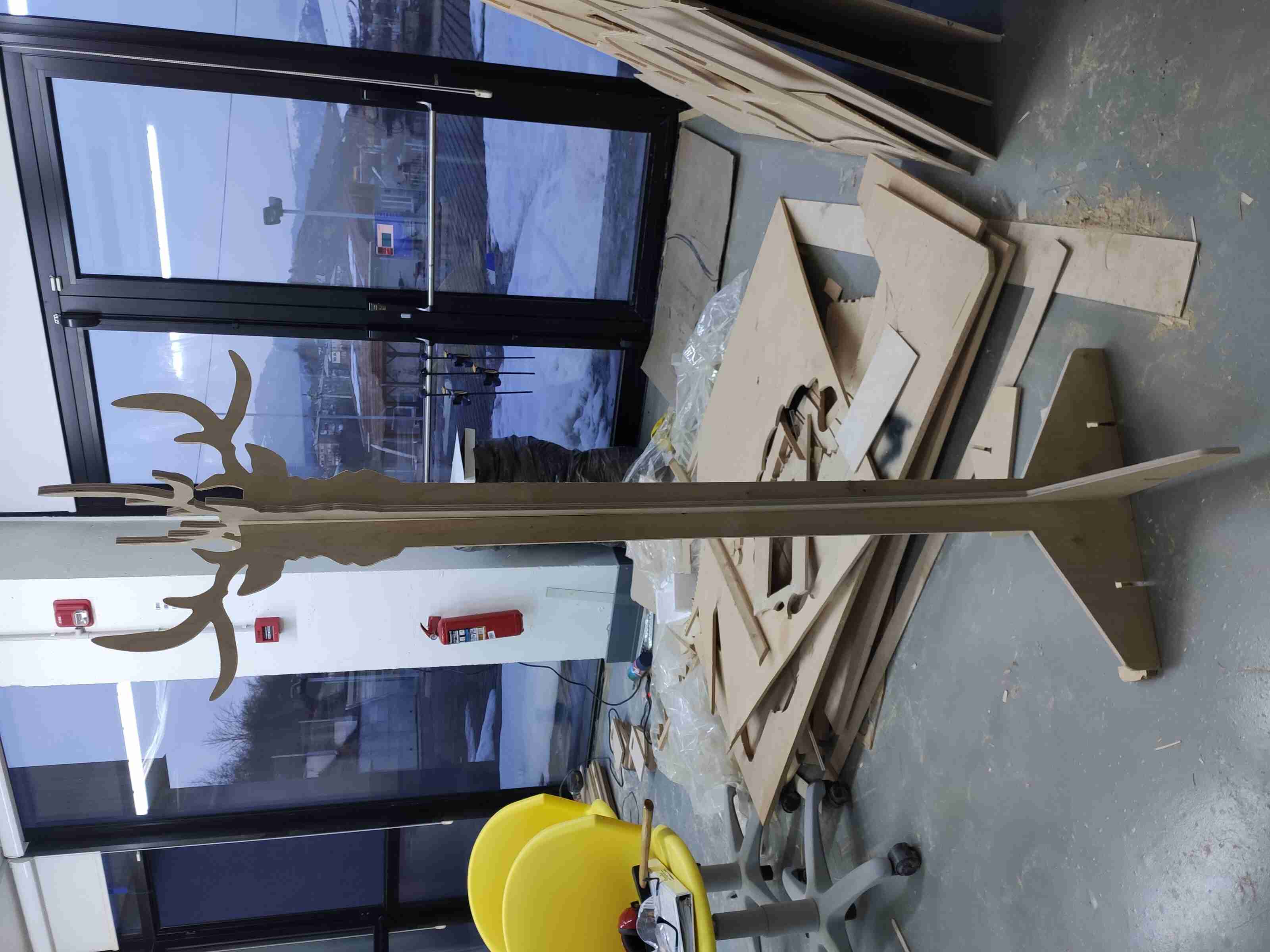
And the pieces were finally ready to be assembled. The final hanger was sturdy (even without the stabilizers) and aesthetic enough to be enjoyed :)
Downloading the files
The files for the slide (not complete) and the deer hanger can be downloaded from the following links:
- The Slide (.f3d, Fusion 360 archive, 102 kB)
- The Slide (.stp, STEP file, 109 kB)
- The Deer hanger (.f3d, Fusion 360 archive, 1.56 MB)
- The Deer hanger (.stp, STEP file, 823 kB)
- The Comparison comb (.sbp, ShopBot file, 38.4 kB)

