Molding and Casting
This week we got familiarized with various molding and casting methods. For our individual assignment, we had to create a 3 stage mold:
- The mold for mold: Use CNC milling to create two molds with the positives (that means in the shape of) the two sides of the object we want to create from waxable mold. This is done from a hard millable material. This should include the positive of the sprue from which the actual mold material is to be poured and the positive of the air hole.
- The mold:Use silicone to cast a negative mold for the object to be cast. This is done with a non-sticking, flexible material so that the final object can be easily removed from this mold.
- The cast:The final object is cast from various materials.
Safety
As all lab-work, the most important thing before beginning is to find out about all the safety information and keep it in mind. This week we had to work with some chemicals, and in any such case, it is of utmost importance to read the Material Safety Data Sheet related to the material and be informed of toxicity, flammability, combustion, and fire hazard information.
Before using any of the chemicals, eye protection, gloves, and overalls must be worn. The gloves are preferred to be vinyl rather than latex as in case of some materials (e.g. Oomoo) they can prevent the cast from curing.

The mold for mold
The design
First idea: Tatik & Papik
The first idea that I had for what I want to create was the Tatik and Papik monument, otherwise known as We Are Our Mountains. It is a sculpture completed in 1967 by Sargis Baghdasaryan, and is widely regarded as a symbol of the Armenian heritage of the region.
I downloaded the .stl design for this file by Vrezh Petrosyan from Thingiverse and uploaded it to Fusion 360 before opening it. Here is what it looks like:
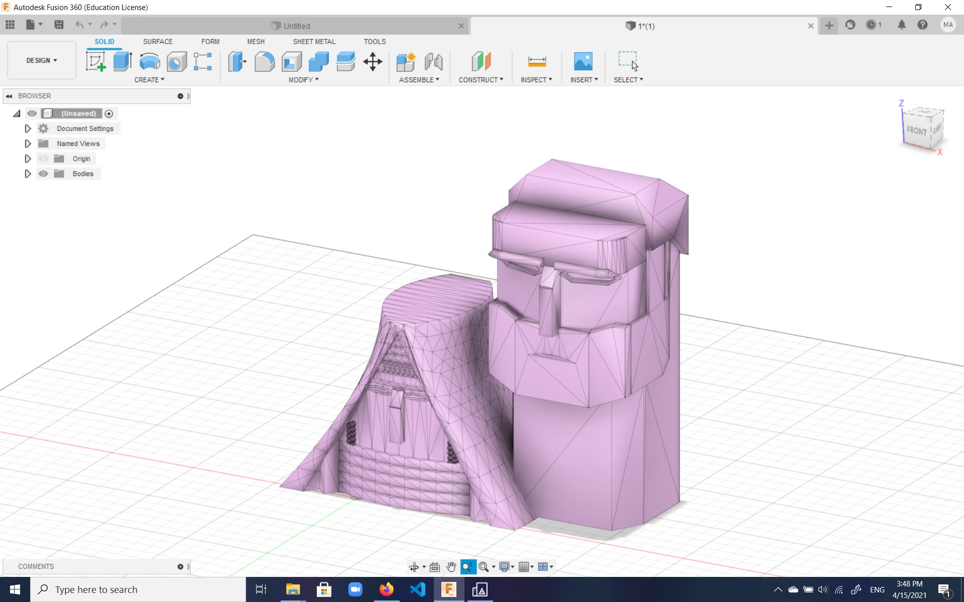
The problem was that this design was a mesh, and eventhough I tried right-clicking the image and selecting Mesh to BRep
to convert it to a solid body (BREP standing for Boundary Representation),
the program would create a surface. After some searching, I found that might be either because a) the mesh is open or b) the normal to
the surface is pointing inside. After some tweaking, I understood the normal was outward as the object was pink, so the
problem must have been an open mesh. I tried to fix that by going to the Mesh tab and using Modify -> Make Closed Mesh
but this didn't seem to work either. Eventually I gave up.
Later I learned that I could've used FreeCAD to turn the mesh into a solid object;
this is done by going to Part → Create shape from mesh. The result can be seen below:
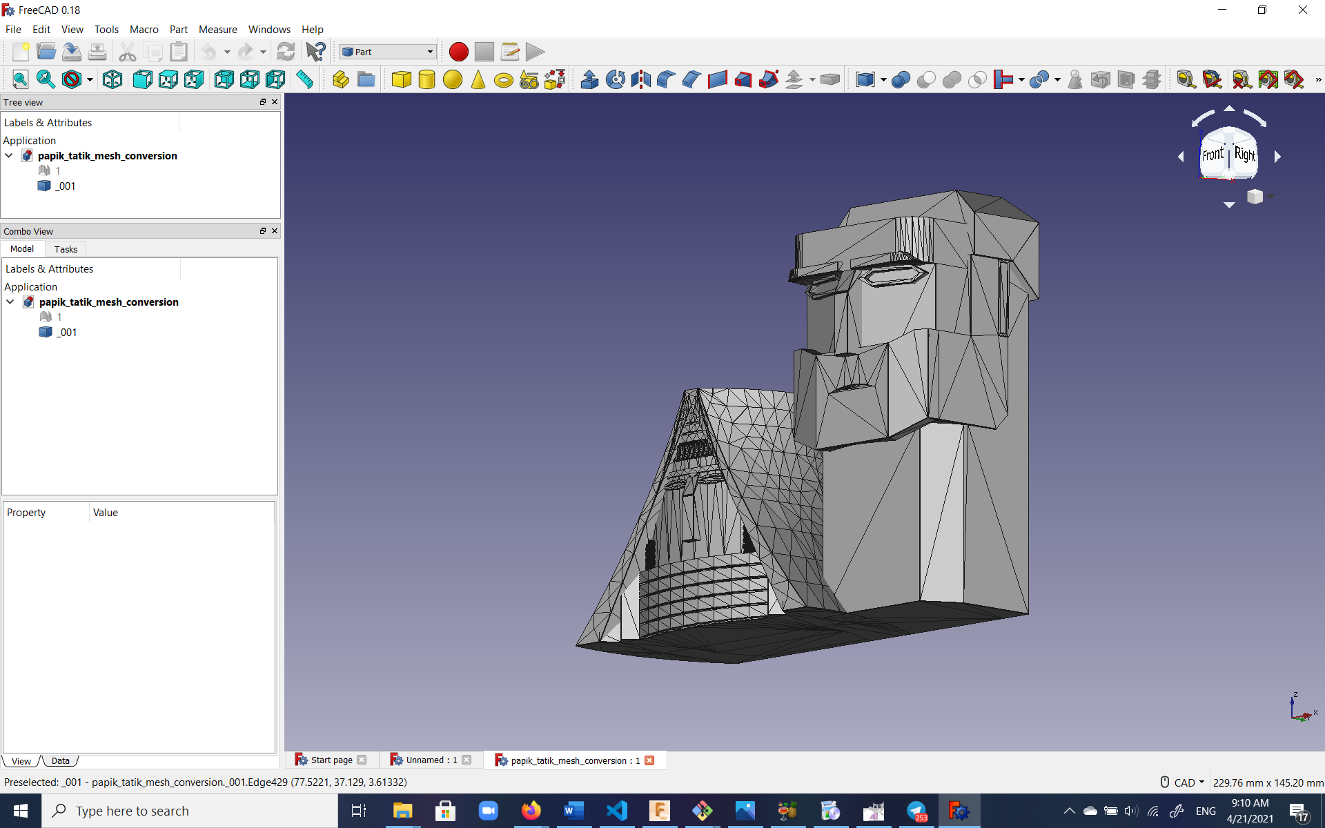
However, by this point I had already turned to designing an egg.
Second idea: The egg
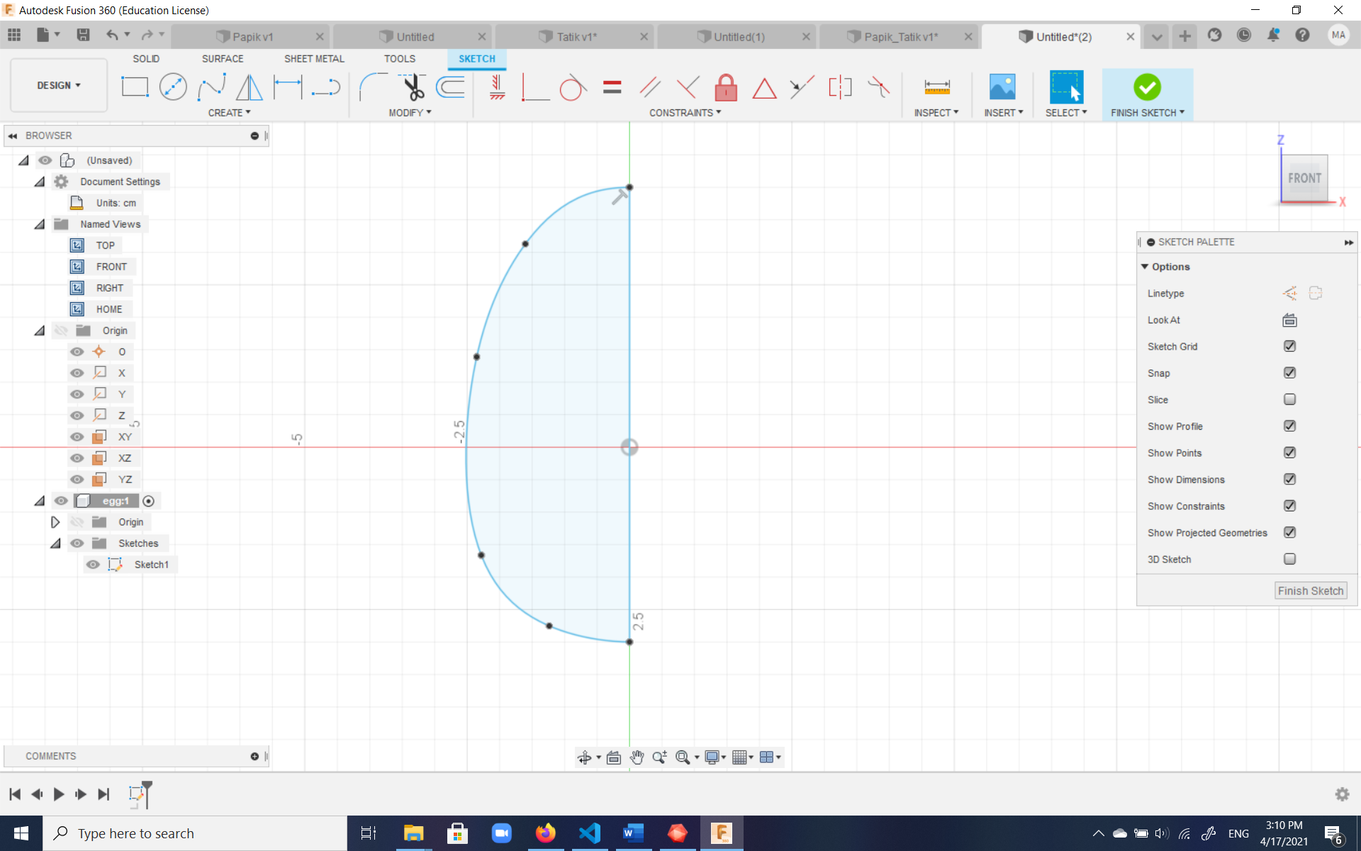
The egg seemed like a good idea because like a sphere, the midsection of the object would be wider than the edges everywhere, making it easy to pull out of both the mold for the mold and the actual mold. In order to practice more, I wanted it to be a decorated egg with patterns on it.
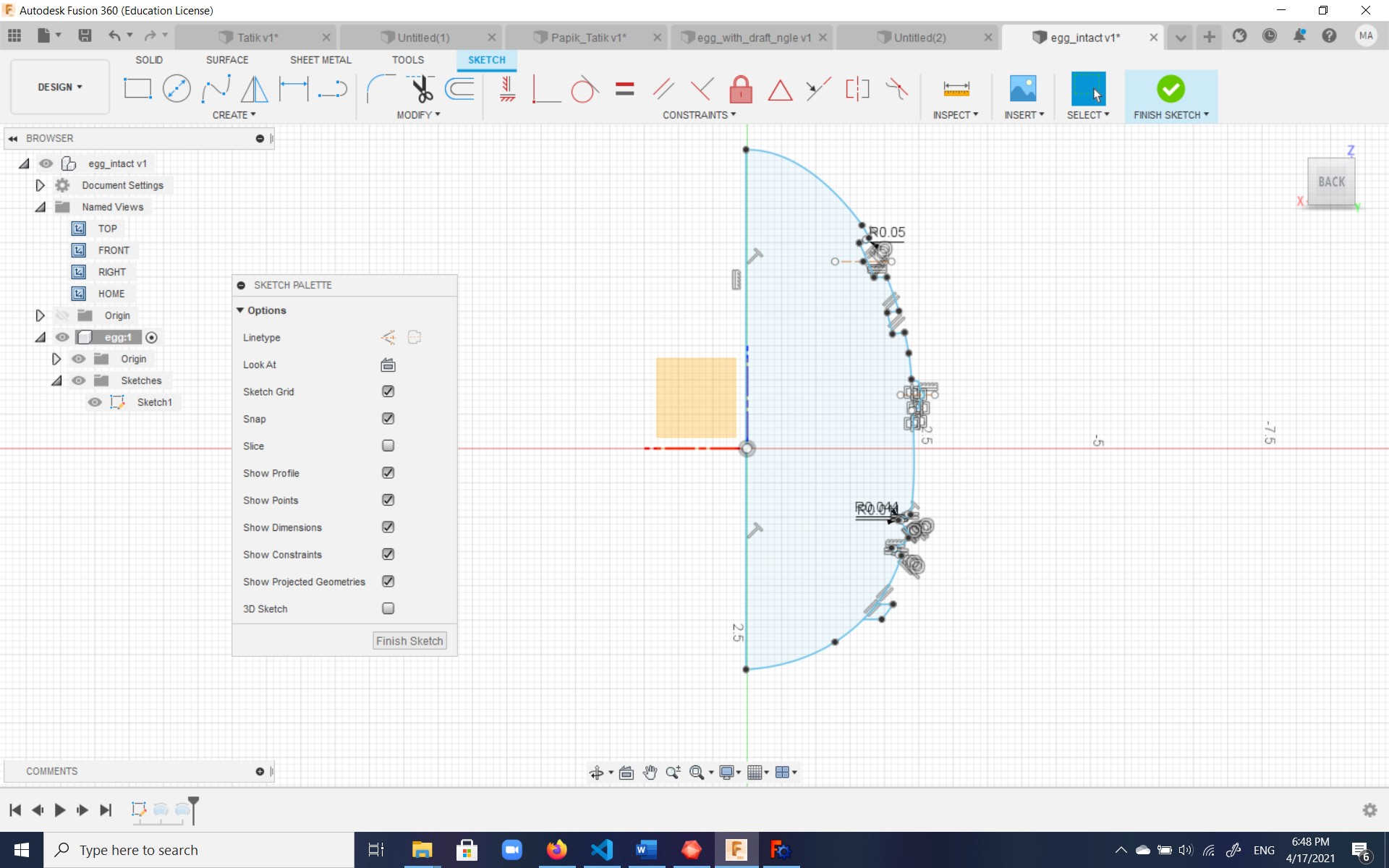
I designed the egg by creating a 2D sketch of half the egg in Fusion 360 and revolving it 360° to get the whole egg; not bad considering it's done from memory alone:
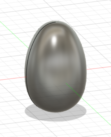
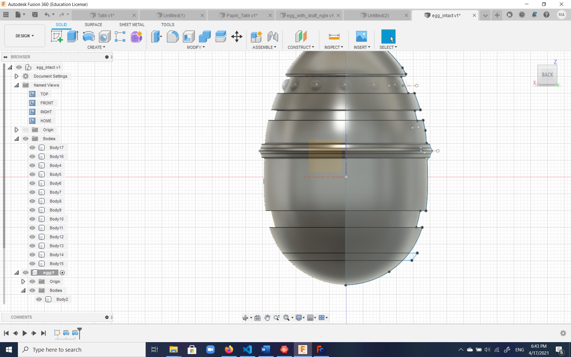
Then I started to add most of the patterns to the sketch since final patterns could be achieved by revolving. The little spherical pattern was achieved by adding one intersecting sphere body to the egg surface and patterning it in a circular fashion:
After extruding a box with drift angles to encompass the egg, a sprue a air hole were added:
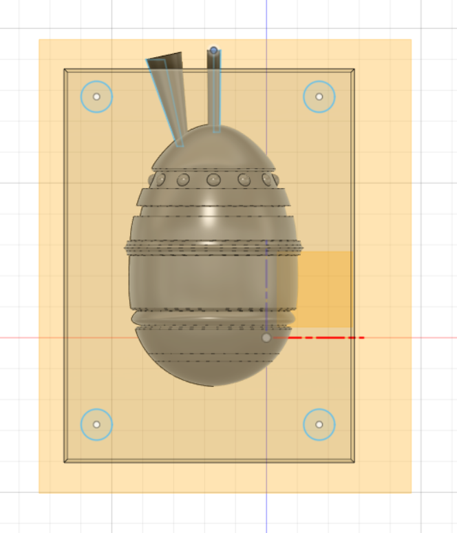
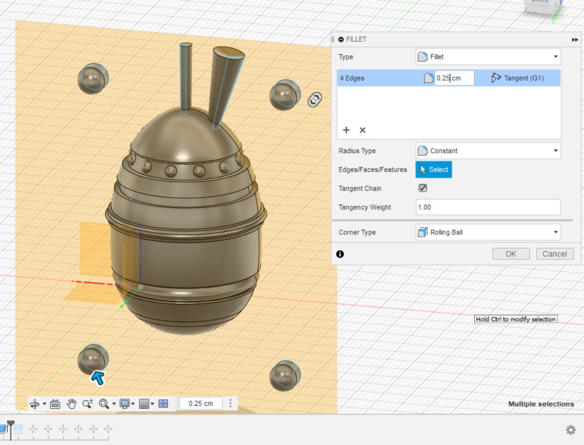
Then uni-axis circles were created on the four sides of the egg on a plane passing through the middle of the egg so that registration keys could be developed. These circles were extruded to one side and filleted with a radius of 2.5 mm:
The egg and its box were then split in half using the midplane through the egg. The cylinders for the registration keys were then subtracted from one box while keeping the tools (the cyliners), and afterwards joined with the other box while getting rid of the tools:
The two boxes containing halves of the egg were then rotated to lie side-by-side on one plain and the sprue and air hole were trimmed using the boundary surface of one of the boxes:
At this point an edge was added to the mold in order to make pulling out of the flexible mold easier instead of prying with a knife and other object and damaging it per the tips I read on Adrian Torres's page.
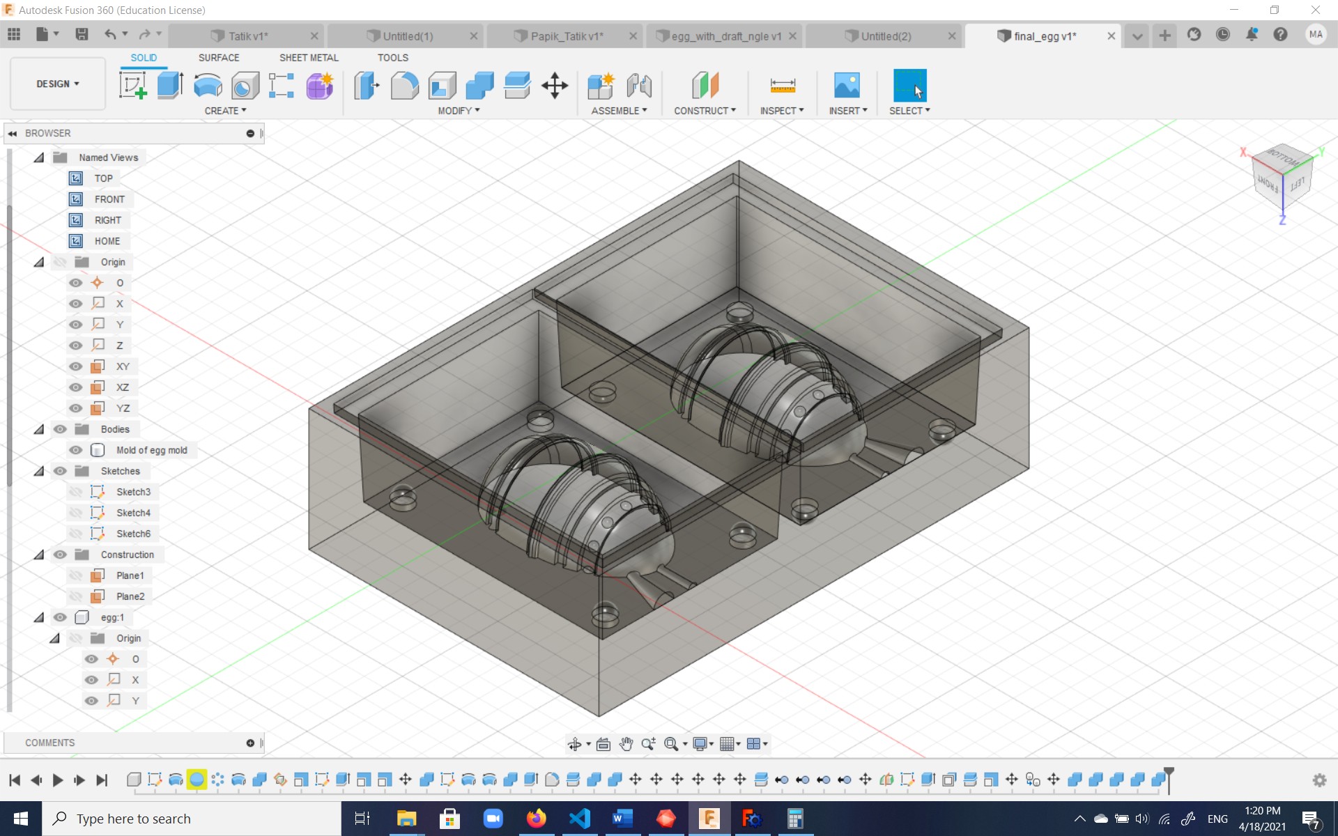
Afterwards, a larger box was created around the whole thing:
After subtracting the egg from the inner box, and then subtracting the remainder of the inner box from the outer box, the final mold for mold was created:
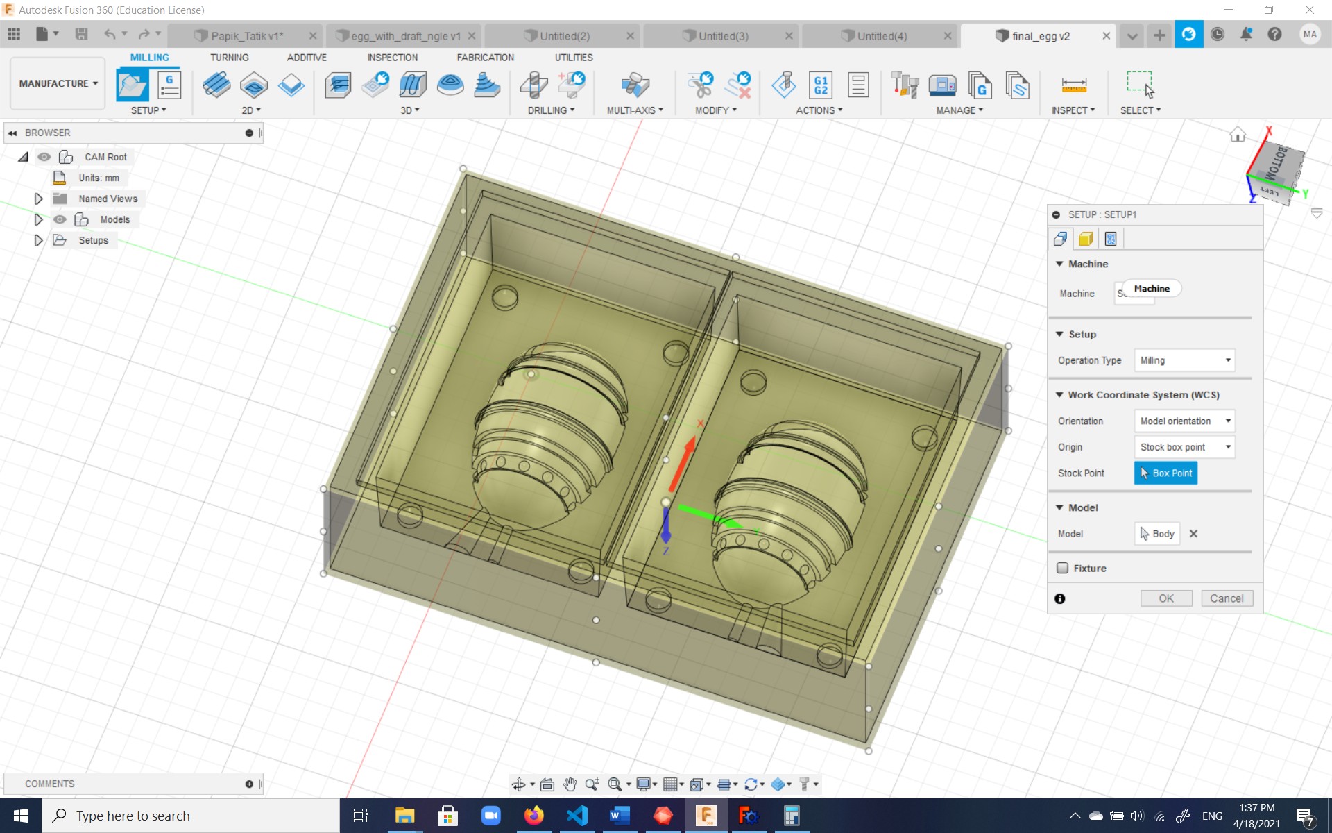
The setup for milling
The setup for milling was done through the Manufacture tab of Fusion 360 again, though an alternative used by many is the Fab Modules software.
Under the Manufacture tab, firstly setup was done for the machine and stock to be manufactured. In our case, we would be using machinable wax available in rectangular cubes at the lab.
There are three sizes of the machinable wax blocks available at our lab:
- 15.3 x 15.5 x 7.6 cm;
- 17.8 x 7.6 x 3.9 cm;
- 30.4 x 15.3 x 3.9 cm.
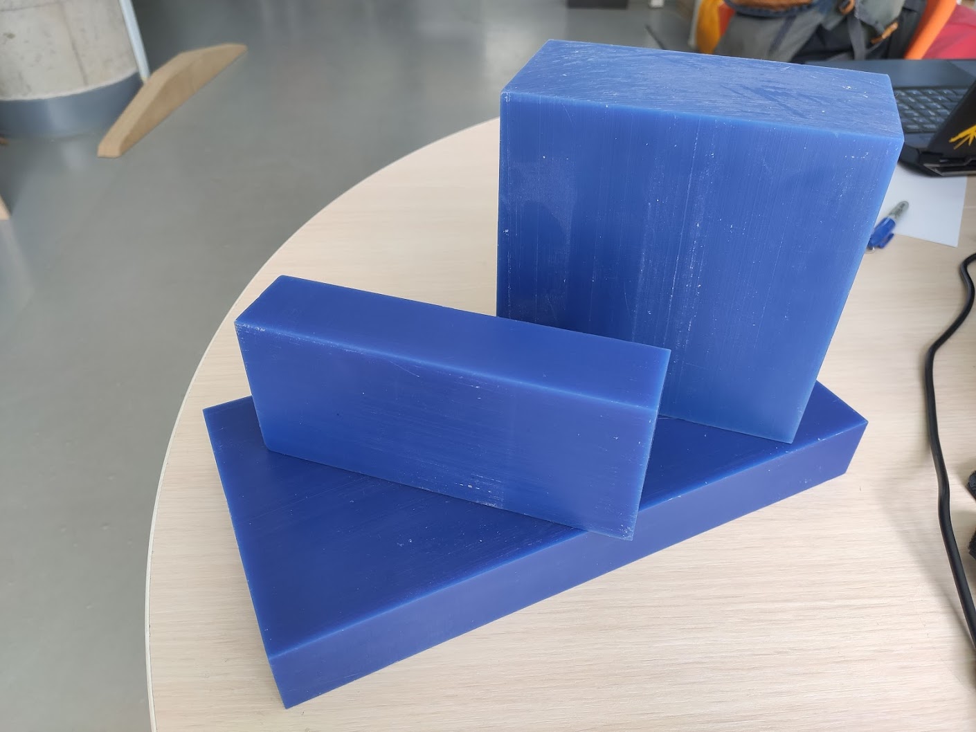
The size that I chose for my project was 17.8 x 7.6 x 3.9 cm.
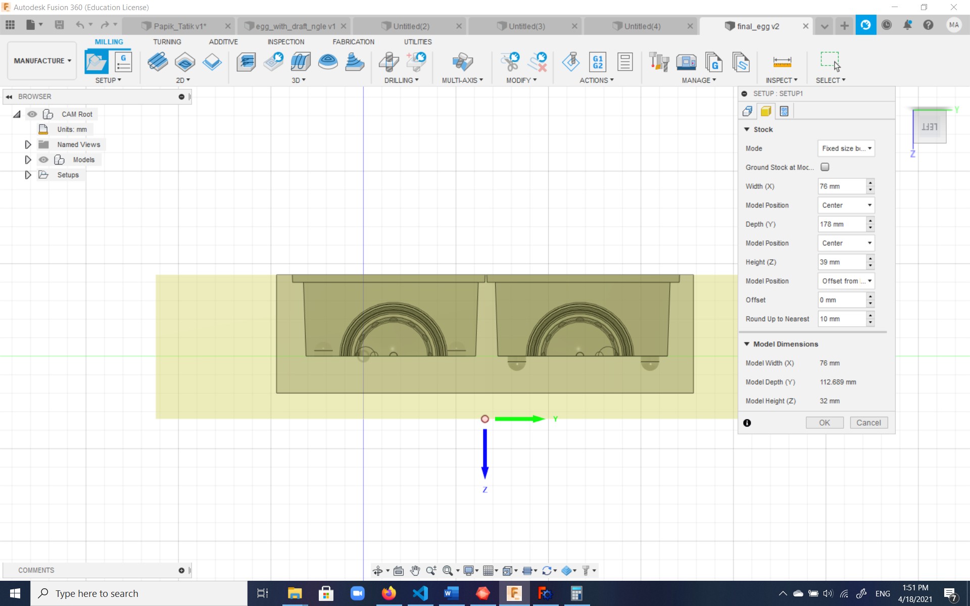
Since the ShopBot machine was not available among machine choices in setup, that was left blank. The stock size was setup under the relevant tab:
At the recommendation of Neil, Ohad, and our instructor Ashot it was decided that the milling would be done in two stages:
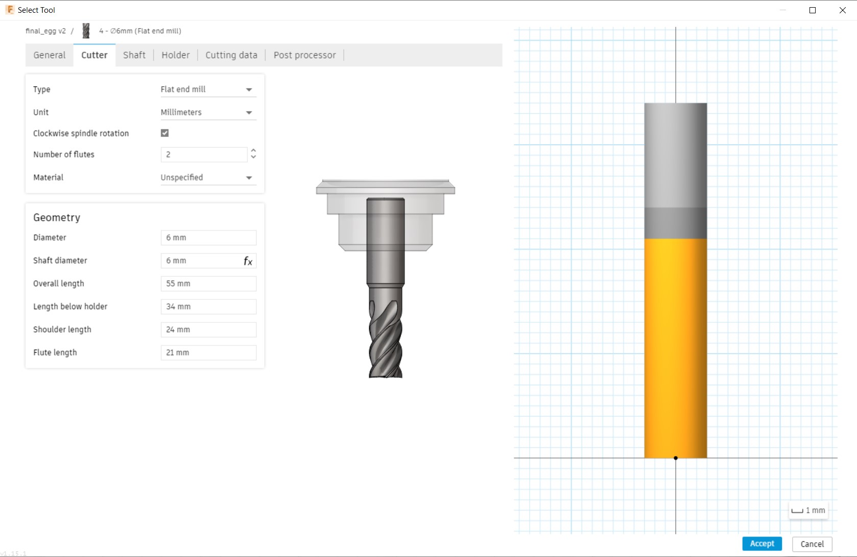
- Roughing milling using a 6 mm diameter flat mill using Pocket Clearing,
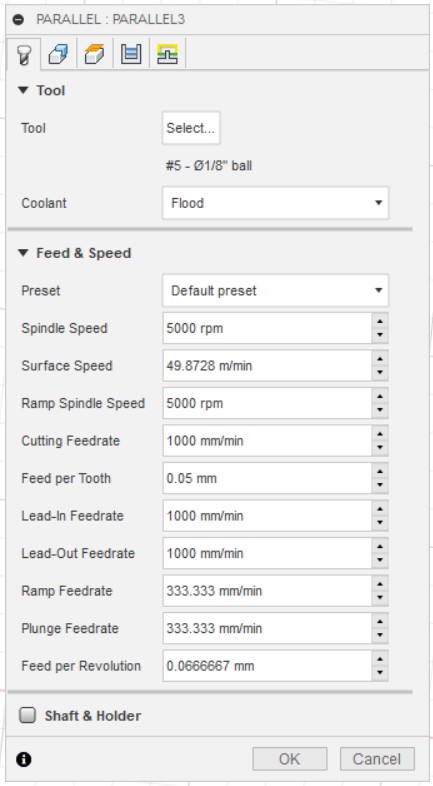
- Finishing milling using a 1/8" diameter ball-end mill using Parallel milling.
Roughing
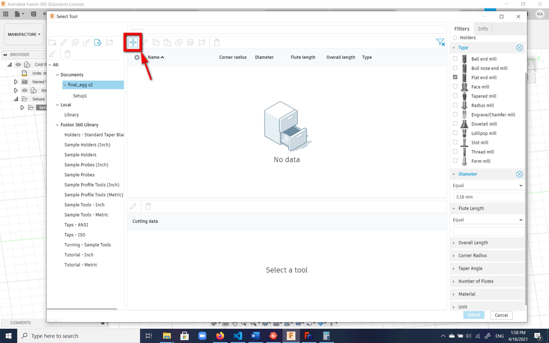
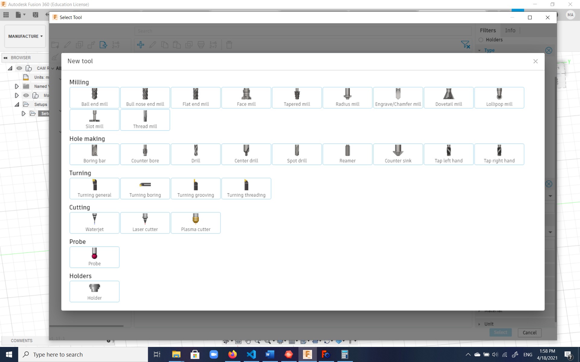
For setting up the roughing, Pocket Clearing was chosen.
A tool had to be selected and its specs defined as follows:
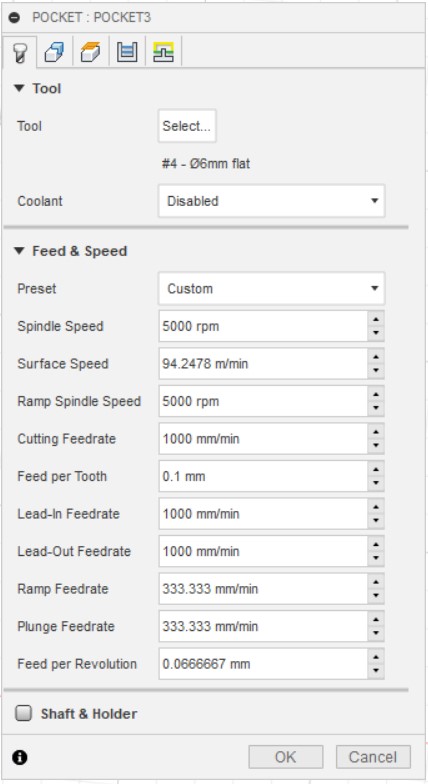
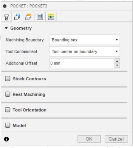
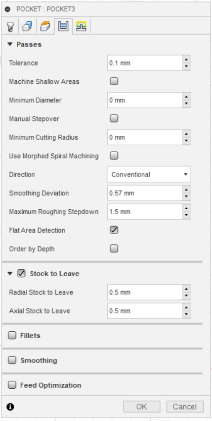
Then the Pocket Clearing setup was done with the following specs; the rest of the tabs were left as default:
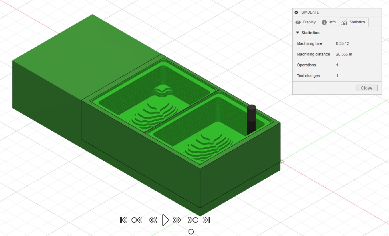
A simulation of the action was then done. In the statistics tab of the Simulate option, it shows how long the roughing would take:
Finishing
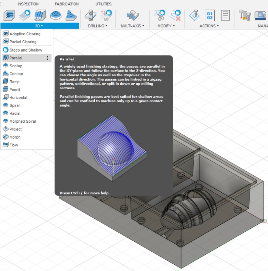
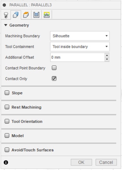
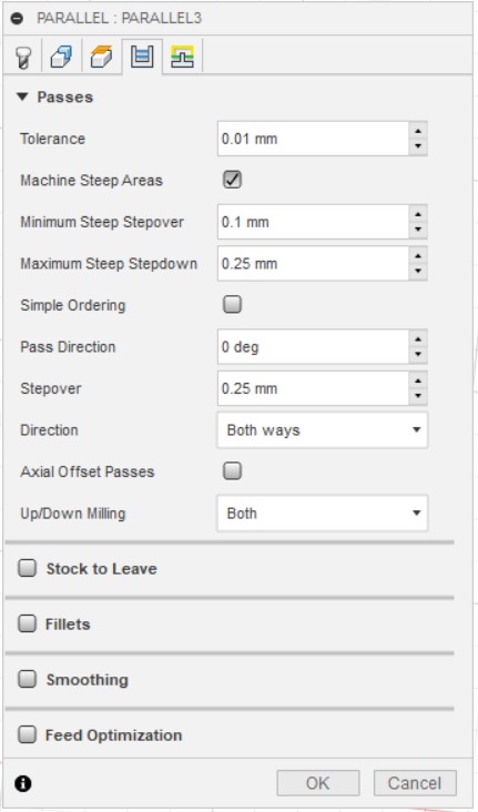
For setting up the finishing, Parallel milling was chosen.
Then the setup was done with the following specs; the rest of the tabs were left as default:
A simulation of the action was then done. In the statistics tab of the Simulate option, it shows how long the finishing would take:

In the end, each of the relevant milling settings (roughing and finishing) were right-clicked upon and Post Process
was selected, at which point the relevant folder could be chosen and after clicking Post, the result
could be saved as an .sbp file (which can be opened by any text editor) and could be used by ShopBot for milling.
The milling, or creating the positive mold for negative mold-creation
The mold for mold should be milled out of machinable wax using a milling machine, in my case, a ShopBot CNC mill, though the Reynolds SRM mill is also an option.
In order to attach the waxable mold to the CNC mill surface, initially two-sided tape was applied underneath the wax block and a heavy object placed on top. To make sure it didn't move under sheer stress, wood pieces parallel to the block were placed on three sides of the block, then holes were made in the wood using a drill with bits slightly smaller than screws to be used, and then the wood pieces were screwed to the surface using the drill-driver.
The ShopBot CNC mill and the attached computer were turned on. Then the x and y axes were zeroed, and eventually the z-axis was zeroed using the anode and cathode of the machine designated for this purpose.
Then the spindle key was taken out to use with a hex key to change the mill on the spindle. A 6 mm flat end mill and a 6 mm collet were used, fit back, and then adjusted on the spindle, and the nut was tightened. The dust collector tube was taken out and the CNC mill area completely clearned so that the wax shavings could later be collected for melting into another wax block and reusing.
The spindle key was then put back and engaged. Cut was selected and the .sbp file generated from
Fusion was loaded and Start selected. Afterwards, the physical green Start button was hit, which
started the spindle, and the milling progressed.
Initially, the roughing milling was done:
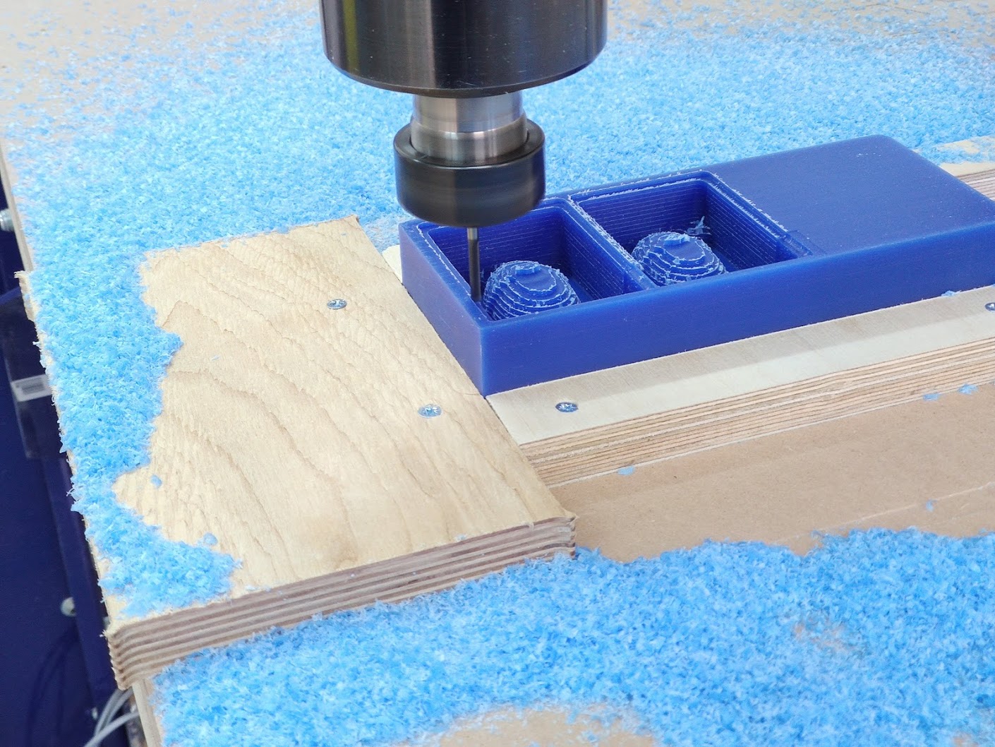
Then the 6 mm flat end mill was changed to a 1/8" ball-end mill and fine milling was performed by uploading the finishing file generated from Fusion 360:
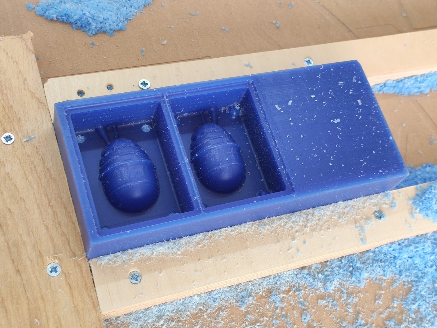
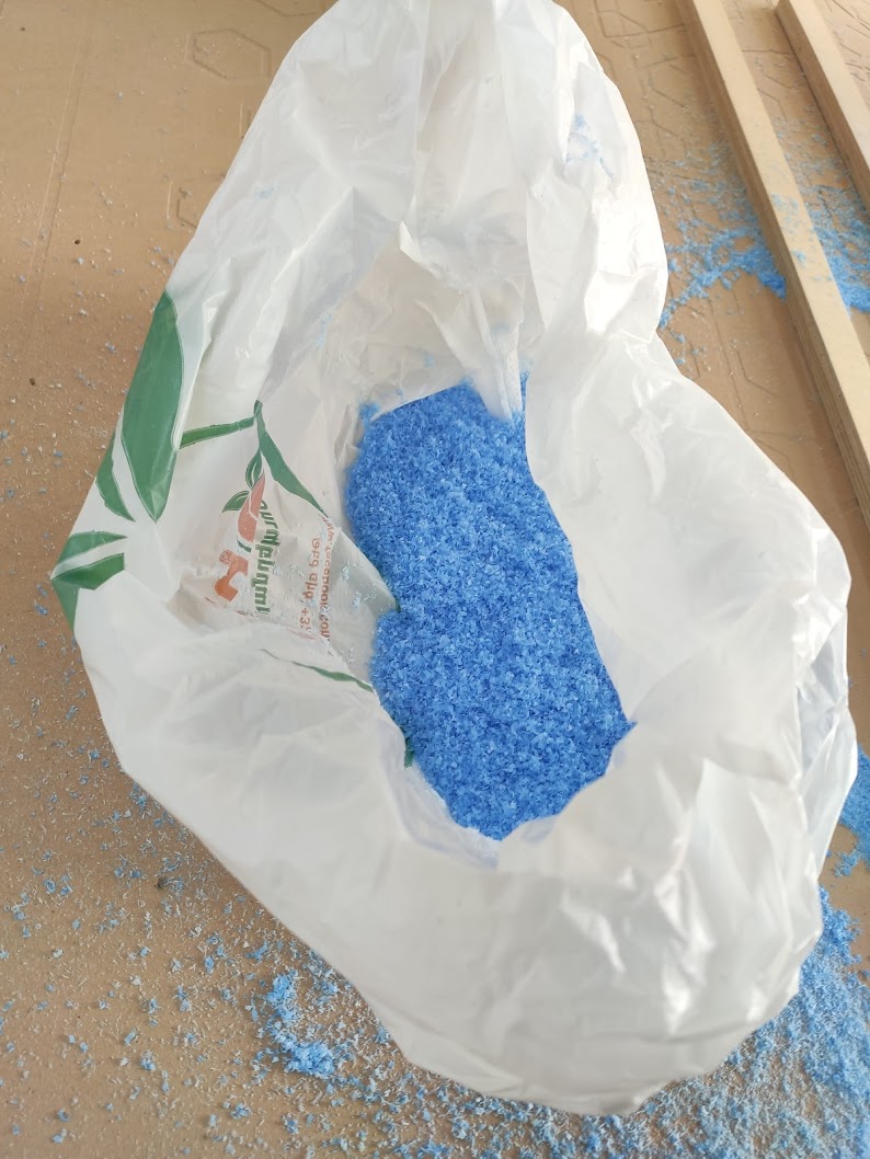
At the end, the wax shavings were collected to be recycled and reused later:
The final mold, or casting the negative mold
For the Group Assignment, we had to cast various materials in the lab and compare. The results can be seen in the relevant page.
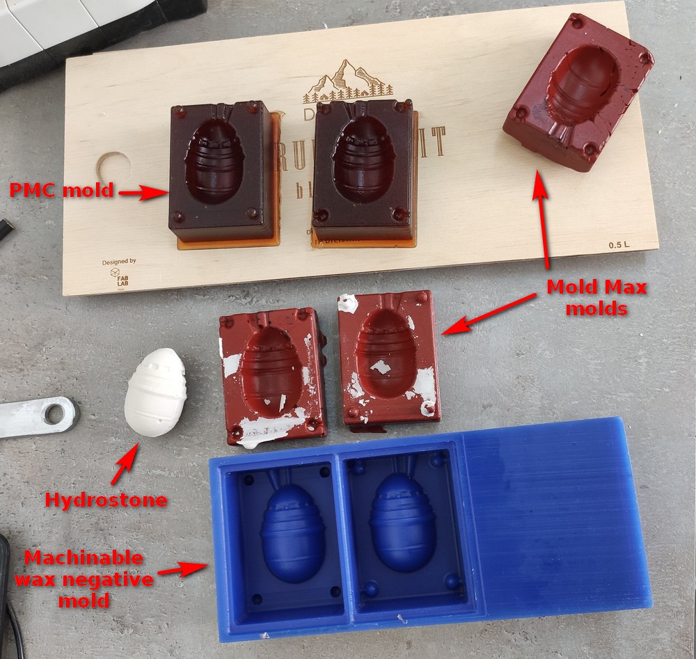
Here is a list of cast materials in the lab that are flexible and would be suitable for casting the final mold:
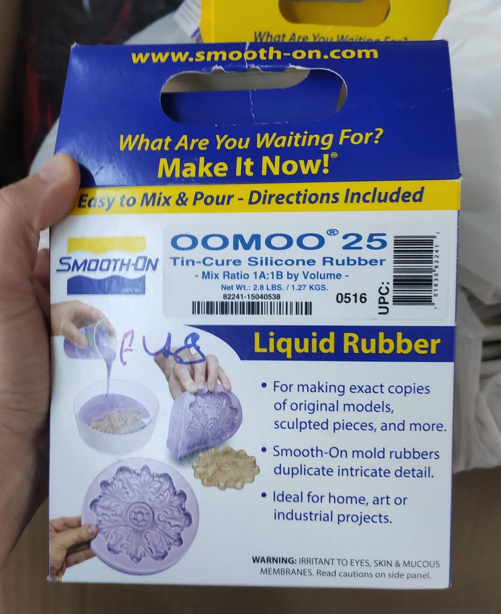
- Oomoo 25: Tin-cast silicone rubber
- PMC 121/30 dry: Urethane rubber
- Mold Max 60: Tin-catalyzed silicone rubber
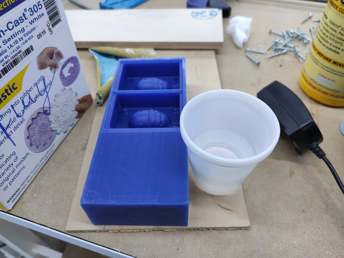
In order to mix the right volume of mold ingredients and not waste any, it is important to measure out the volume of material to be used. For this, I used water. Since the two sides were symmetric, using only one half would be enough to mark the cup to be used, which would then be how much each of parts A and B would need to be used.
I wanted to use Oomoo for this stage of casting the final mold, which requires a 1:1 mixing ratio by volume (so no scale required) but came to find out that Part A had dried up. There were three dried up Oomoo part A's in the lab, so I decided to use other materials.
Among available materials, there was Mold Max 60, which is a heat resistant and toxic rubber compound, and PMC-121/30, for which the cover of part A was stuck and therefore it will be used only if it can be opened.
Mold Max 60
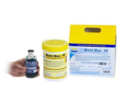
As mentioned in the Group Assignment page, Mold Max 60 is a toxic material, and all safety precautions should be followed before using it. It is mixed by 100A:3B weight ratio. In order to estimate how much total material I need, I looked at the weight of the water volume that I had measured: the empty cup weighed 3.2 g, and filled with water from the mold (not including the edges) weighed 42.7 g, which means the water itself was 39.5 g. The specific volume of Mold Max 60 is 19.1 in3/lb, and that of water at 22°C, which was the temperature at the lab, is 27.741312 in3/lb. We want to calculate the weight of the mold mix that in volume will be equal to the water. Taking the ratios, we get (39.5 g)*(27.741312 in3/lb)=x*19.1 in3/lb ==> x=57.4 g, which is total weight of the Mold Max mixture needed.
This was half the mold (only one side), so it has to be doubled. I'll also add a bit to that to make sure I cover the edges (since the water did not cover the edges) and also to do a test mold in a cup for the group assignment.
Double the size would be 114.8 g, rounding it up and leaving some margin would be 130 g.
So I'll need:
- Part A: 100/103*130 g = 126 g
- Part B: 130 - 126 = 4 g
Before pouring, I tried smoothing the wax surface and edges by using acetone and rubbing it over the edges by Ohad's suggestion, though this seemed to make little difference. Then I washed the mold, dried it with the compressor, and here's when I remembered that I need to measure the volume with water.
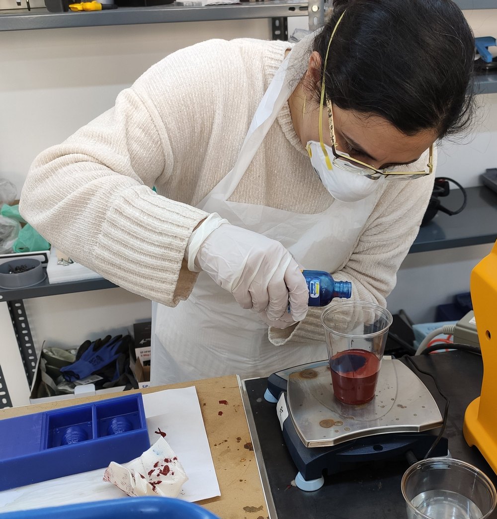
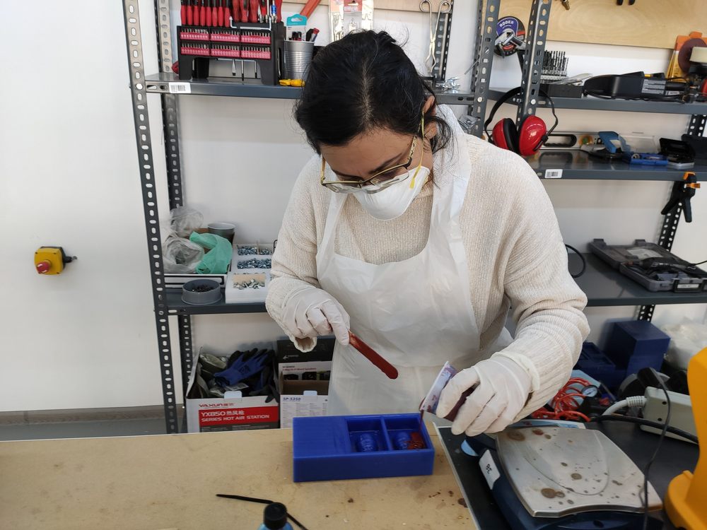
First I opened the doors and windows since we don't have a ventilation hood, put on goggles, a plastic apron, latex gloves (not the best option, but the only one) and a face mask, and started pre-mixing the two solutions: shaking part B, and stirring part A with a tongue depressor stick.
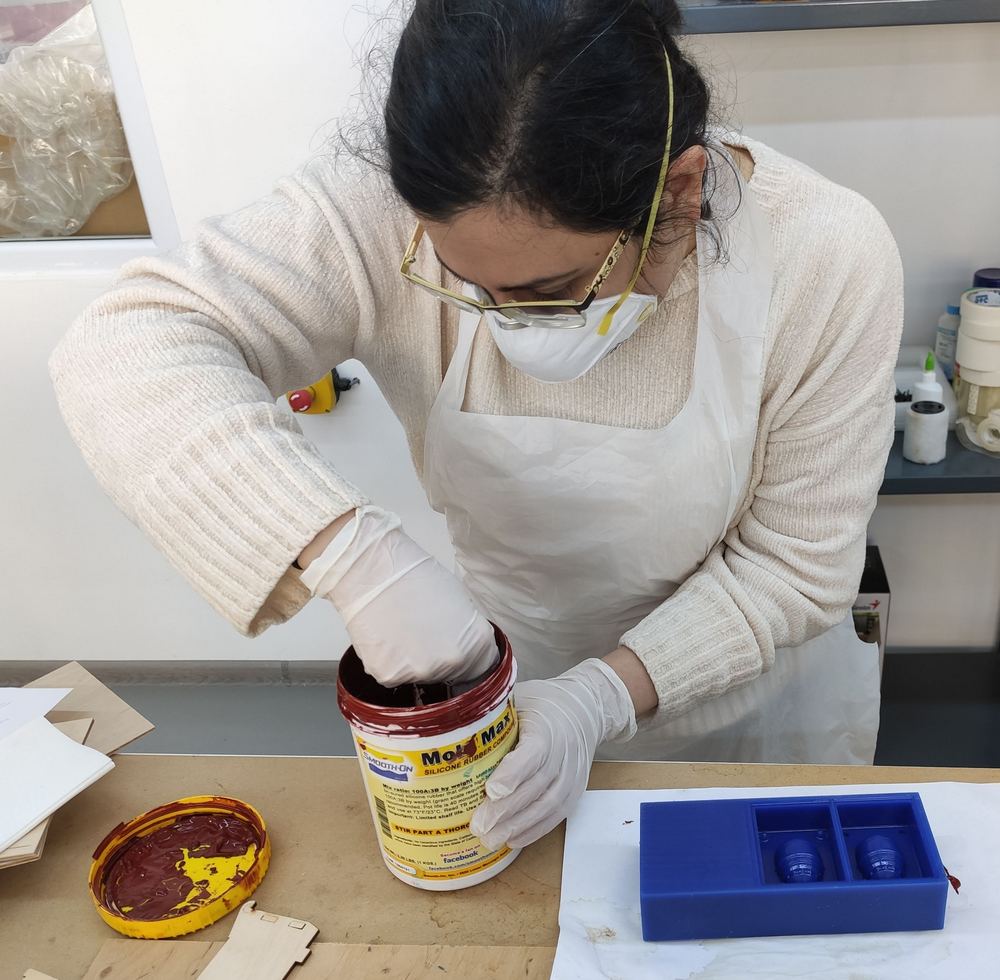
I put an empty cup on top of the digital scale, tared it, and started the pouring part. I first poured part A, and then started adding part B.
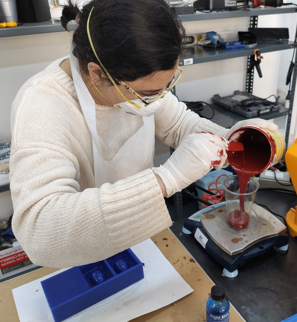
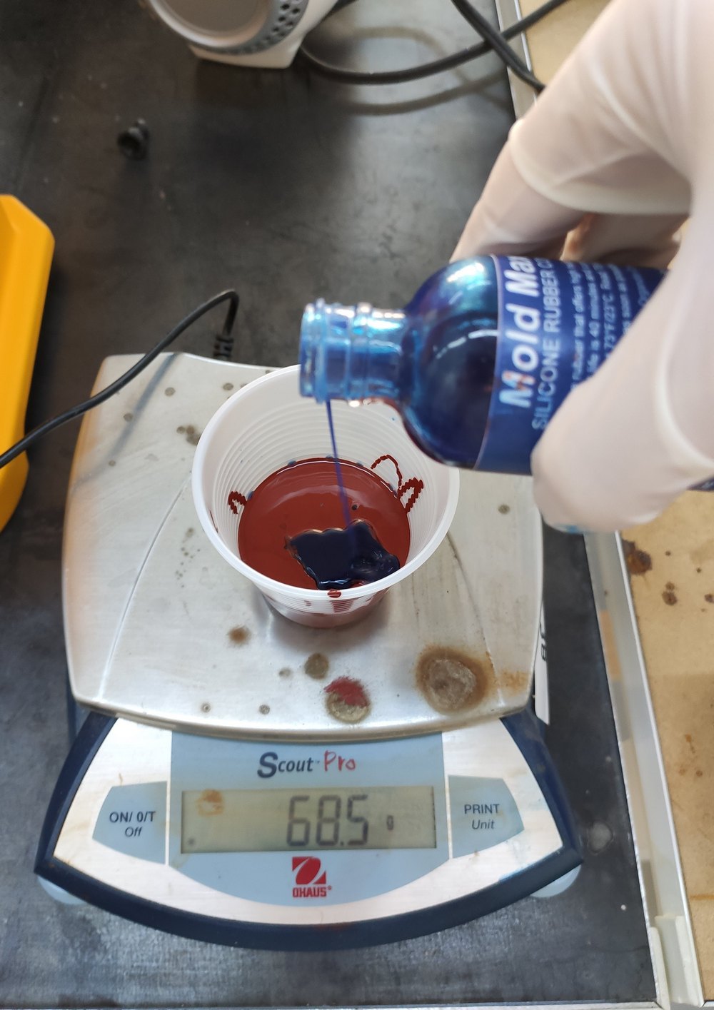
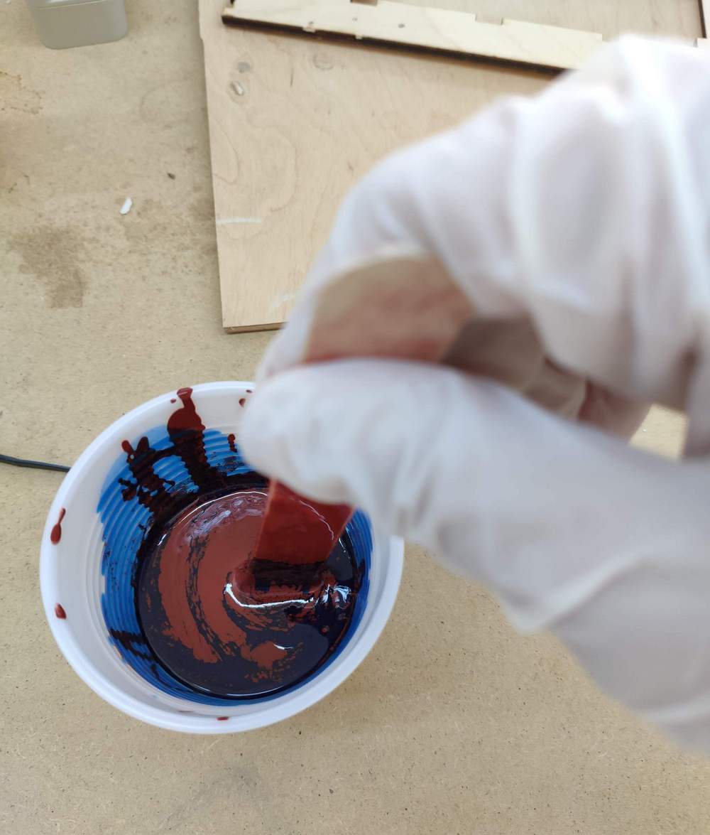
Once done, I started mixing them in horizontal rotating motion using a tongue depressor stick. No vertical motion is permitted to minimize introduction of air in the mixture.
 v
v
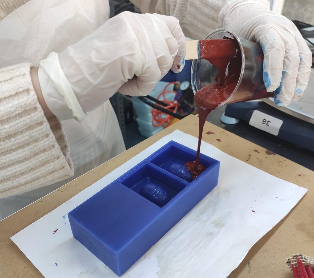
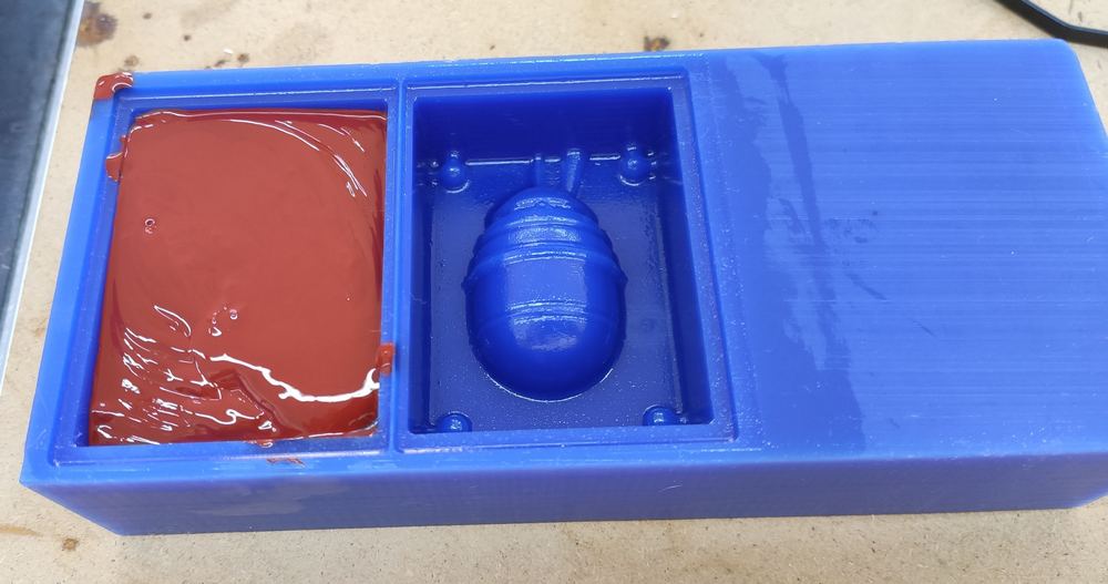
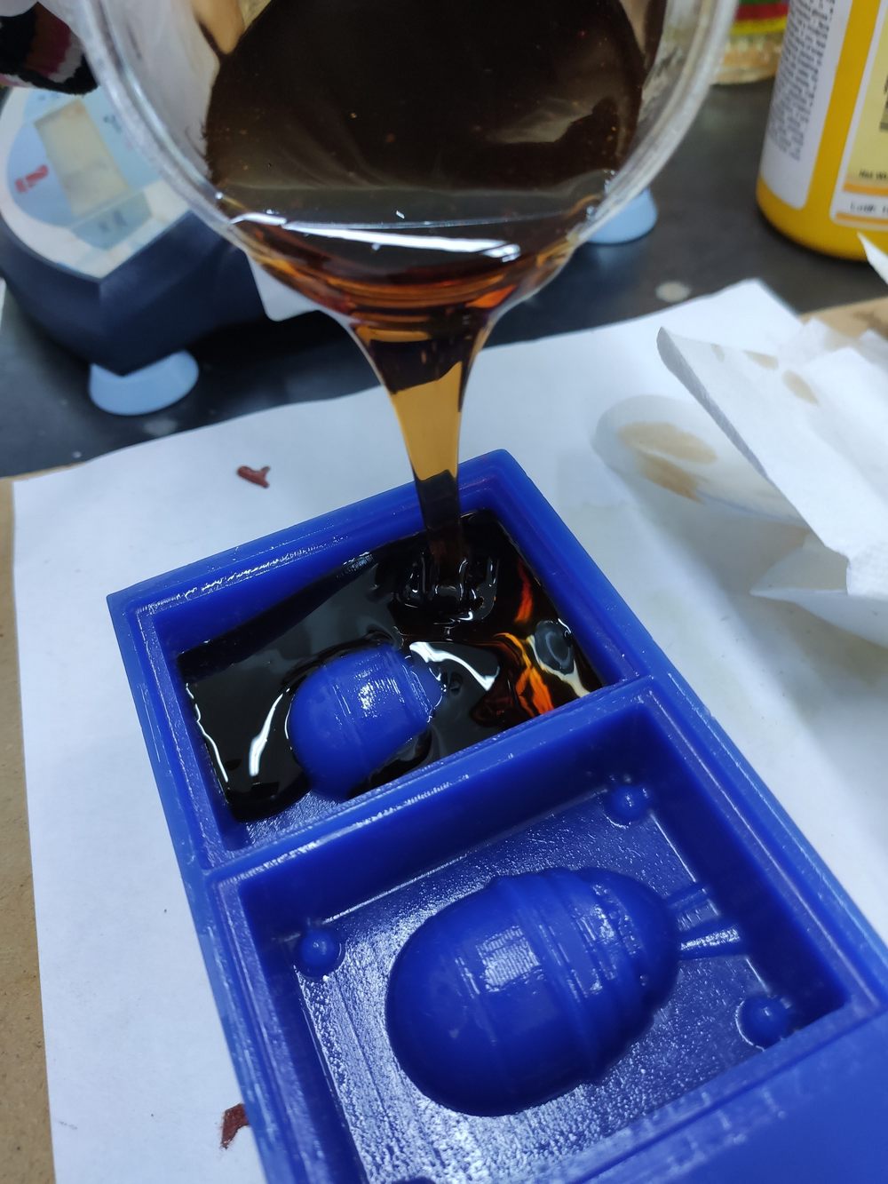
After mixing for about 3 minutes, the mixture was poured in the mold. This had to be from the side of the mold, done slowly in a thin stream, and letting the mixture slowly rise and cover the nooks and crevices of the mold.
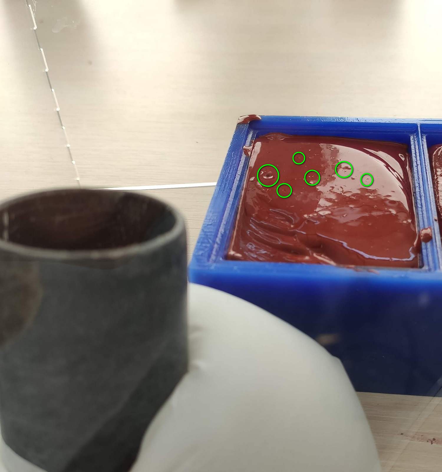
Once the mixture was poured into the mold, the mold was gently bumped onto the table a couple of times to remove residual air bubbles in the mixture.
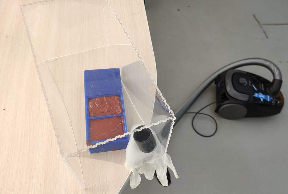
The extract any possible trapped bubbles further, a makeshift vacuum was set up: an upside-down plexiglass box without a cover was used. A household vacuum cleaner was used to create the vacuum, and a latex glove was used to seal the opening between the box and the vacuum tube. This would be done due to the latex glove swelling from vacuum to close any opening remaining there. It can be seen that the longer edges of the plexiglass have bent in, showing that the household vacuum cleaner has created a considerable vaccum.
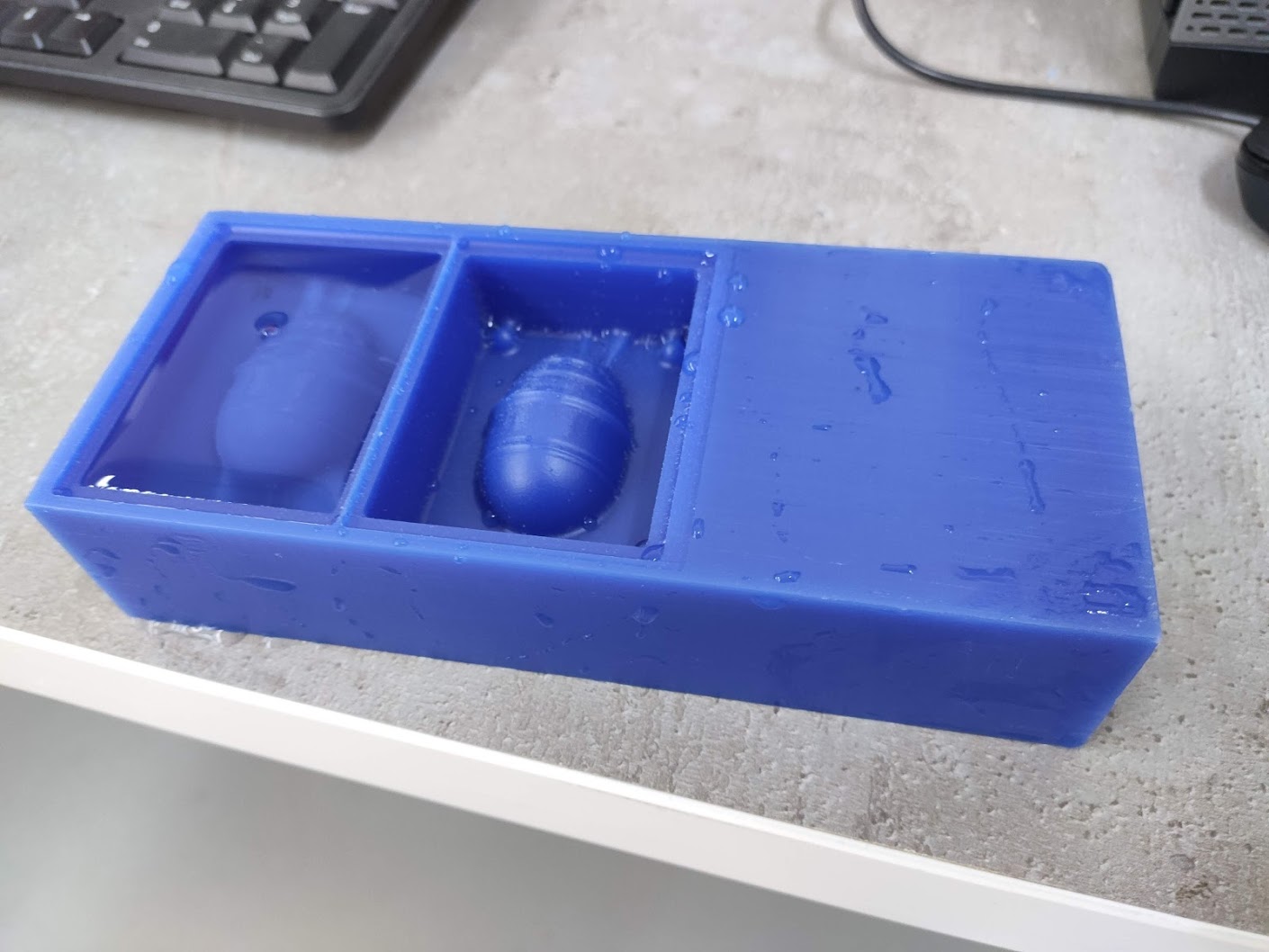
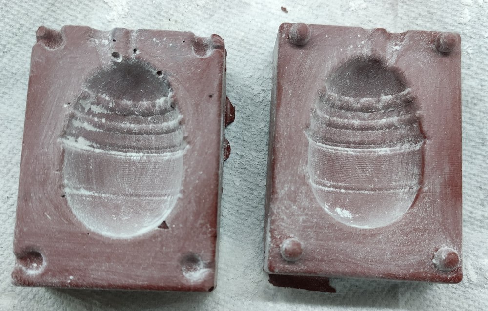
The makeshift vacuum was able to pull air bubbles out of the mold resulting in a smoother, truer-to-design mold:
Here are the results:
Again, as Mold Max has excellent heat resistance properties, it is the only material in our lab that can be used for casting metal, e.g. the Babbit alloy.
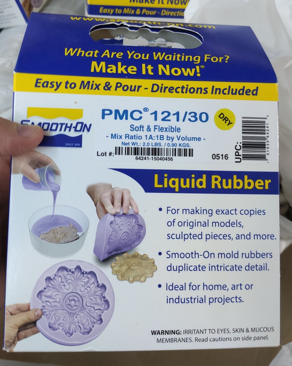
PMC 121/30
PMC 121 is urethane rubber mold material from Smooth-On. We were lucky to have it available at the lab. It comes in two variaties: PMC 121-30 and PMC 121-50, with different strength and tensile properties, as well as mixed viscosity.
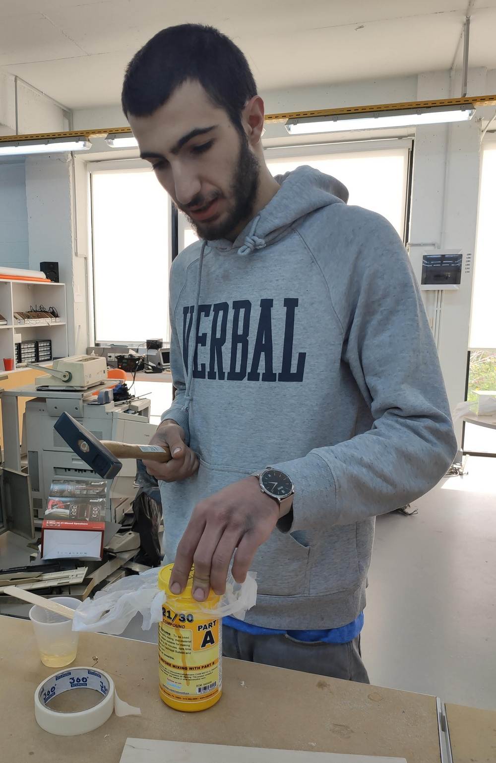
As mentioned before, the cover for part A of this material was stronlgy stuck to the container, and no matter how hard I tried, I couldn't get it off.
The solution came in the form of our instructor, Ashot, who helped me get it off by striking it strongly with a hammer:
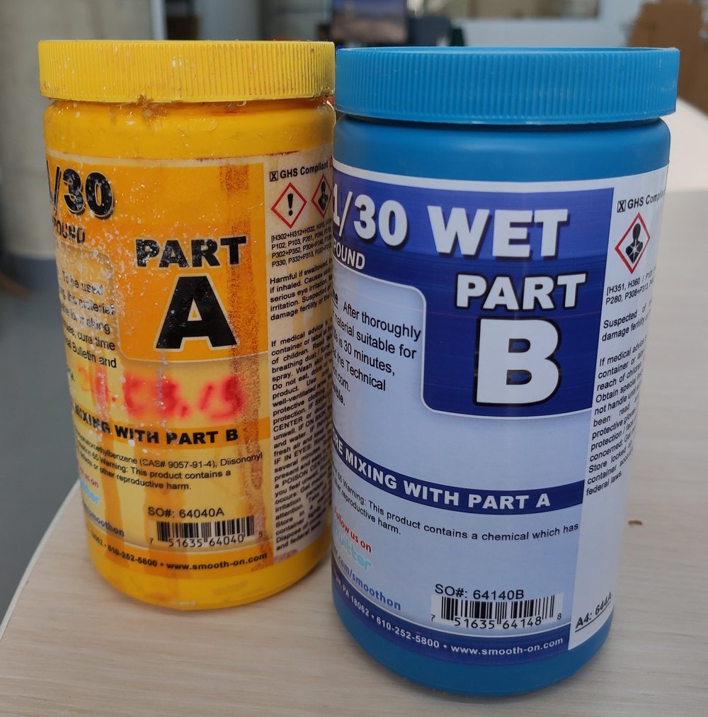
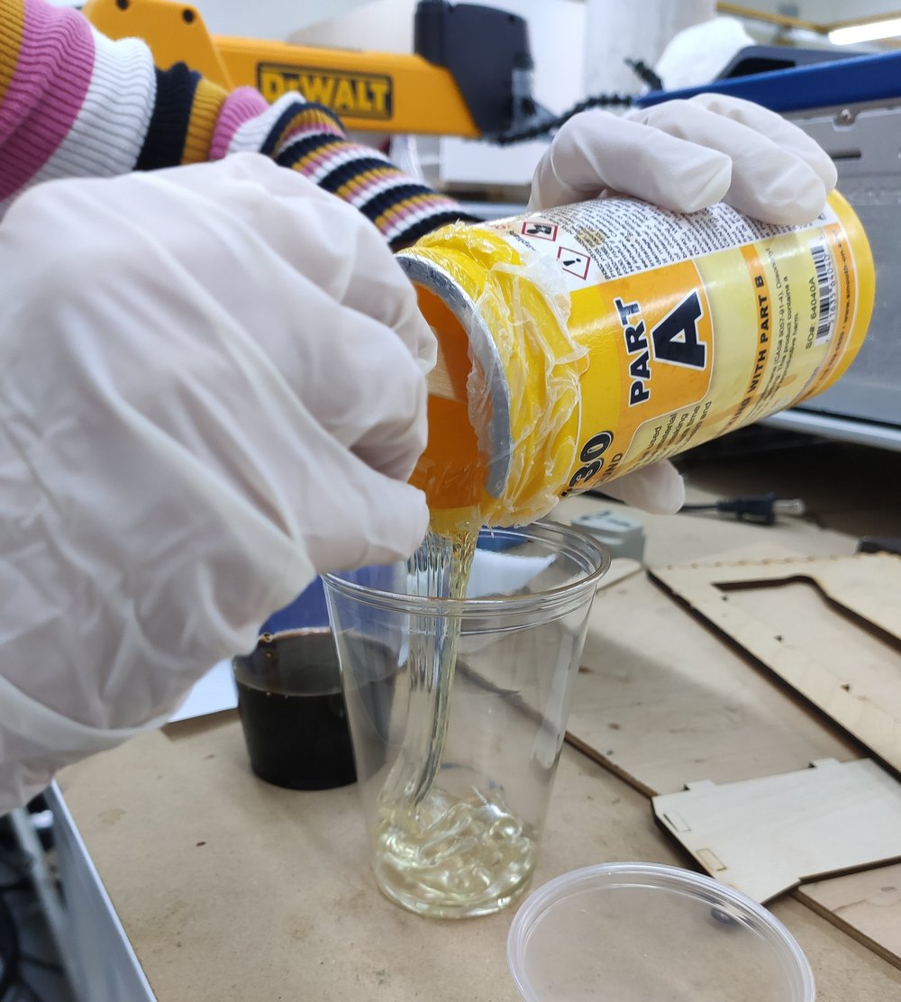
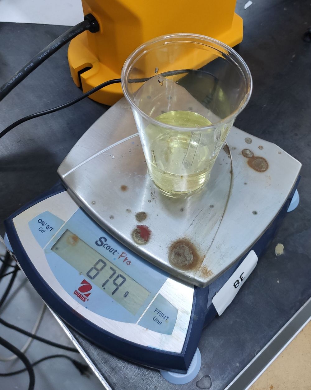
Once the cover was released, we could get to work. Once again, the mold was washed and dried using the air compressor. Then regular sunflower oil was applied as a release agent. PMC part A and B can be combined in a 1:1 ratio, either by weight or volume, since the two parts apparently have the same density. I poured and measured PMC part A:
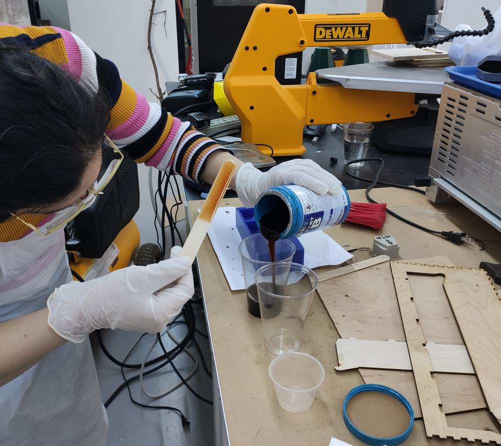
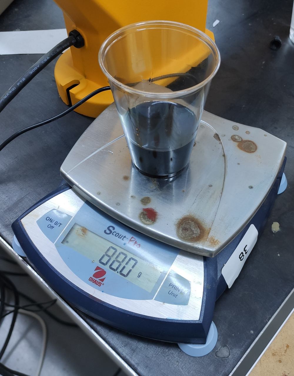
Next, I poured part B and measured it:
Then part B was poured onto part A, and once again, mixed gently in a horizontal rotational motion. The recommended mixing time was 3 minutes. During this lab assignment, I learned that the recommended mixing time usually refers to the minimum mixing time (I learned it the hard way since I initially assumed that mixing more would lead to hardening of the mixture, so once poured it without mixing enough in the designated time). PMC mixture should be mixed thoroughly for at least 3 minutes making sure that the sides and bottom of the mixing container are scraped several times.
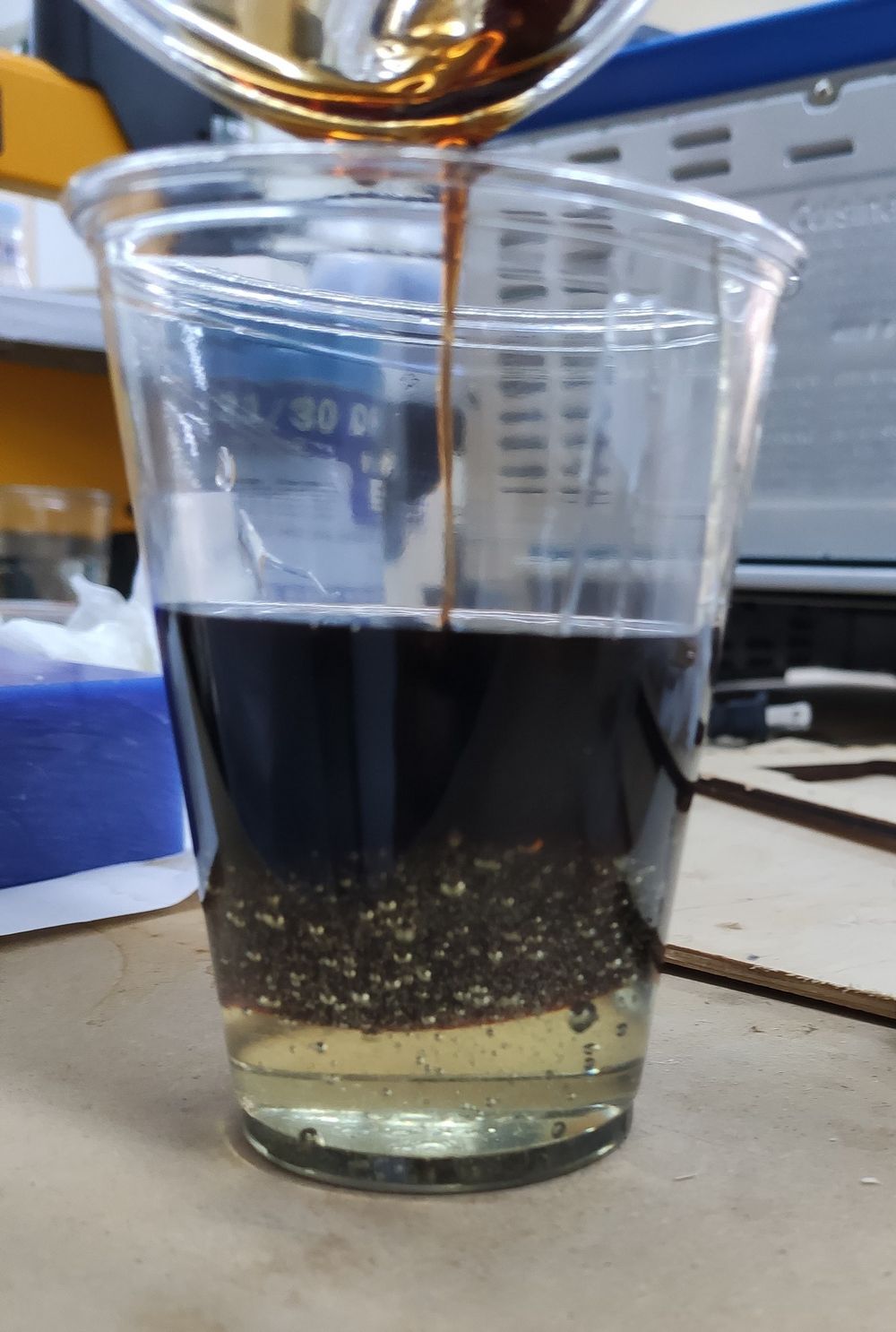
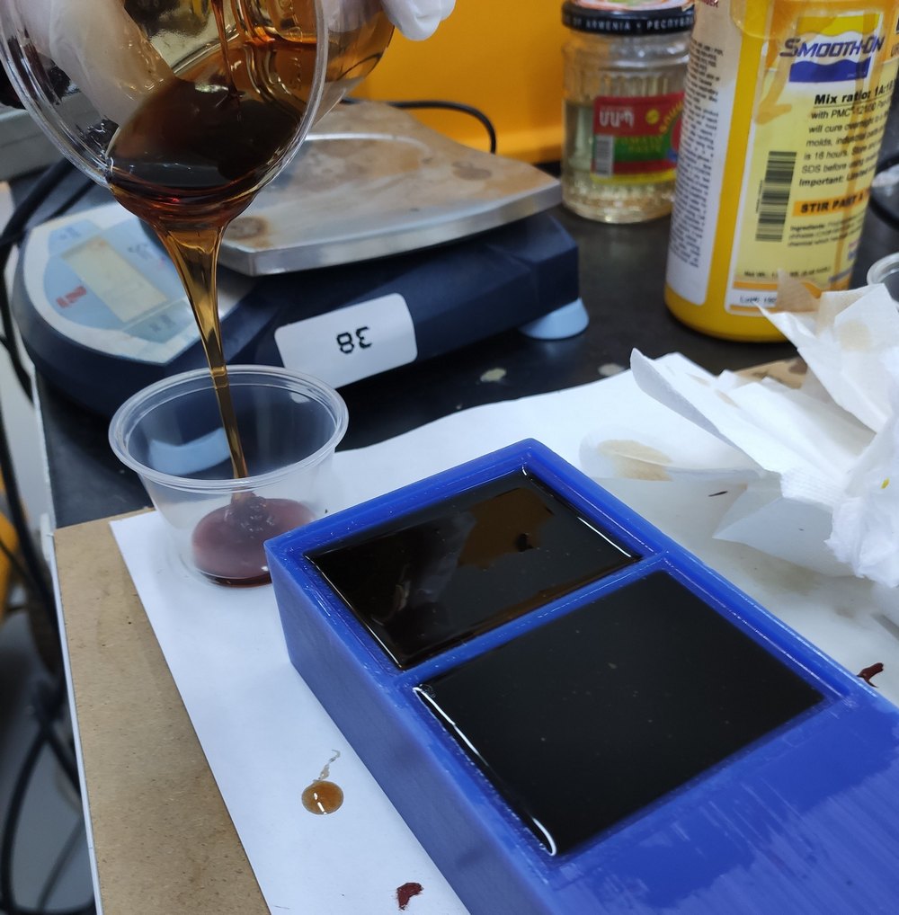
The PMC was poured once again in a slow, thin stream from a corner, and let spread and rise from there:
The final, poured PMC contained lots of bubbles:
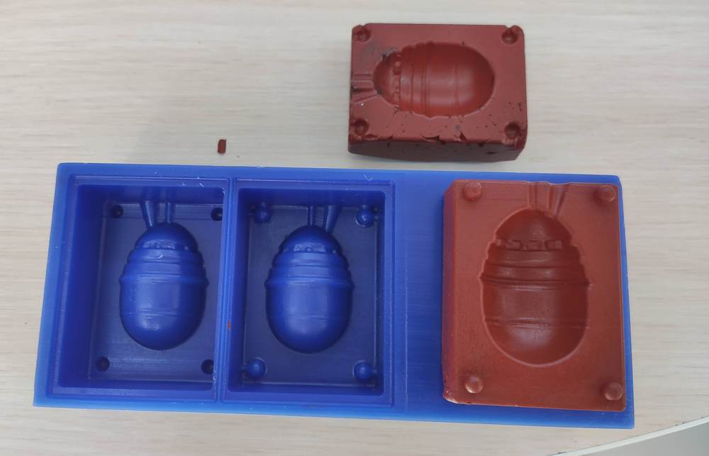
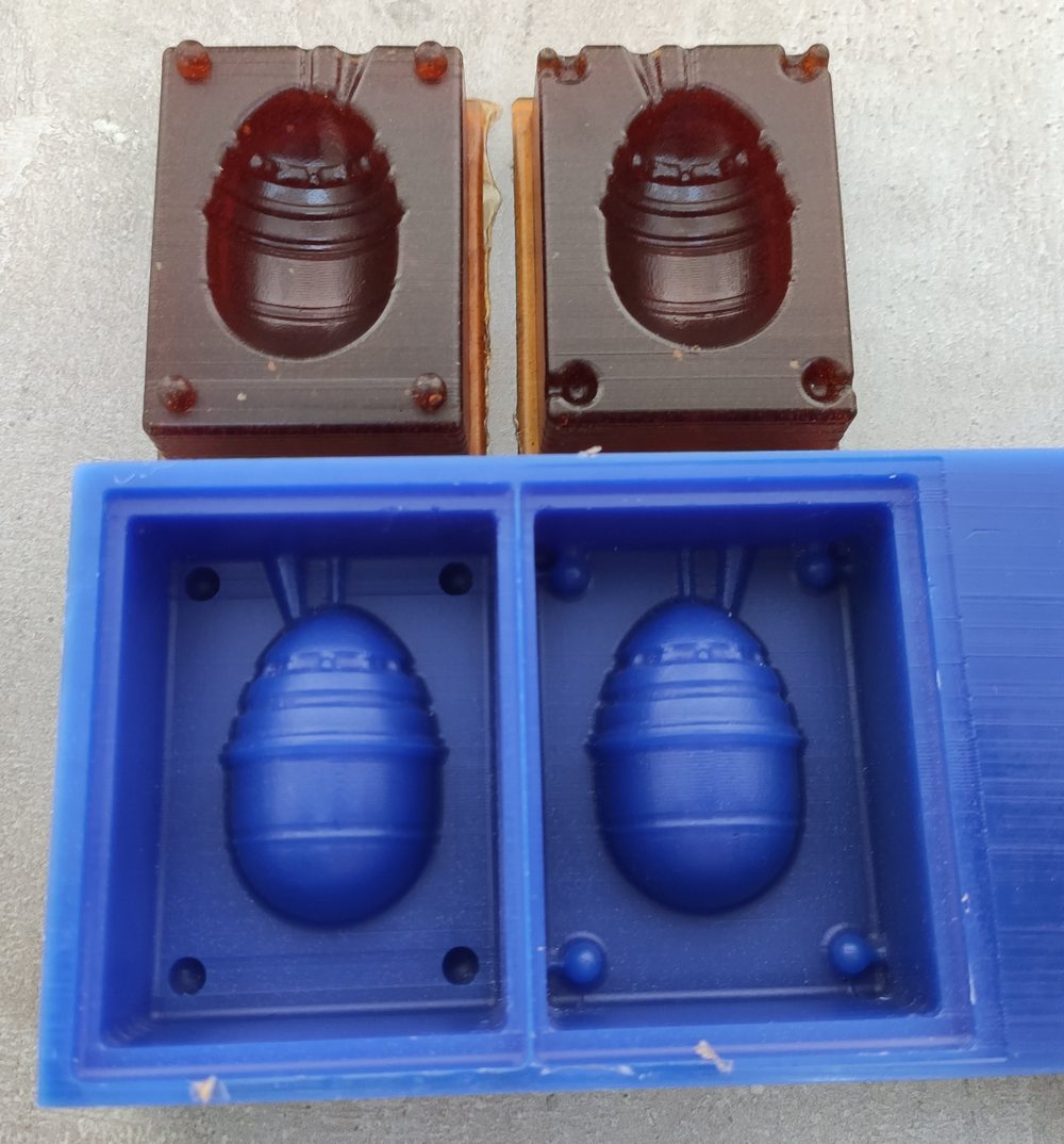
Once again, the makeshift vacuum was used to pull out the bubbles from the PMC, and the final result had a smooth surface finish:
The cast
For casting, we were lucky to have a few material available at the lab. They included:
- Smooth-Cast 305 liquid plastic: Bright white casting resin
- HydroStone: Gypsum Cement
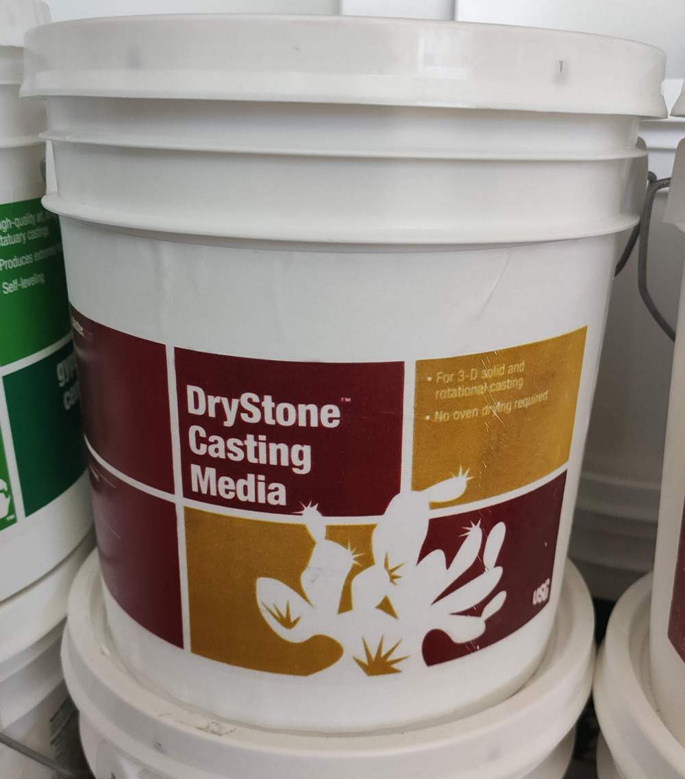
- DryStone: Plaster
- Babbit alloy: These can be mainly tin or lead-based and I don't know which one exactly we have at the lab.
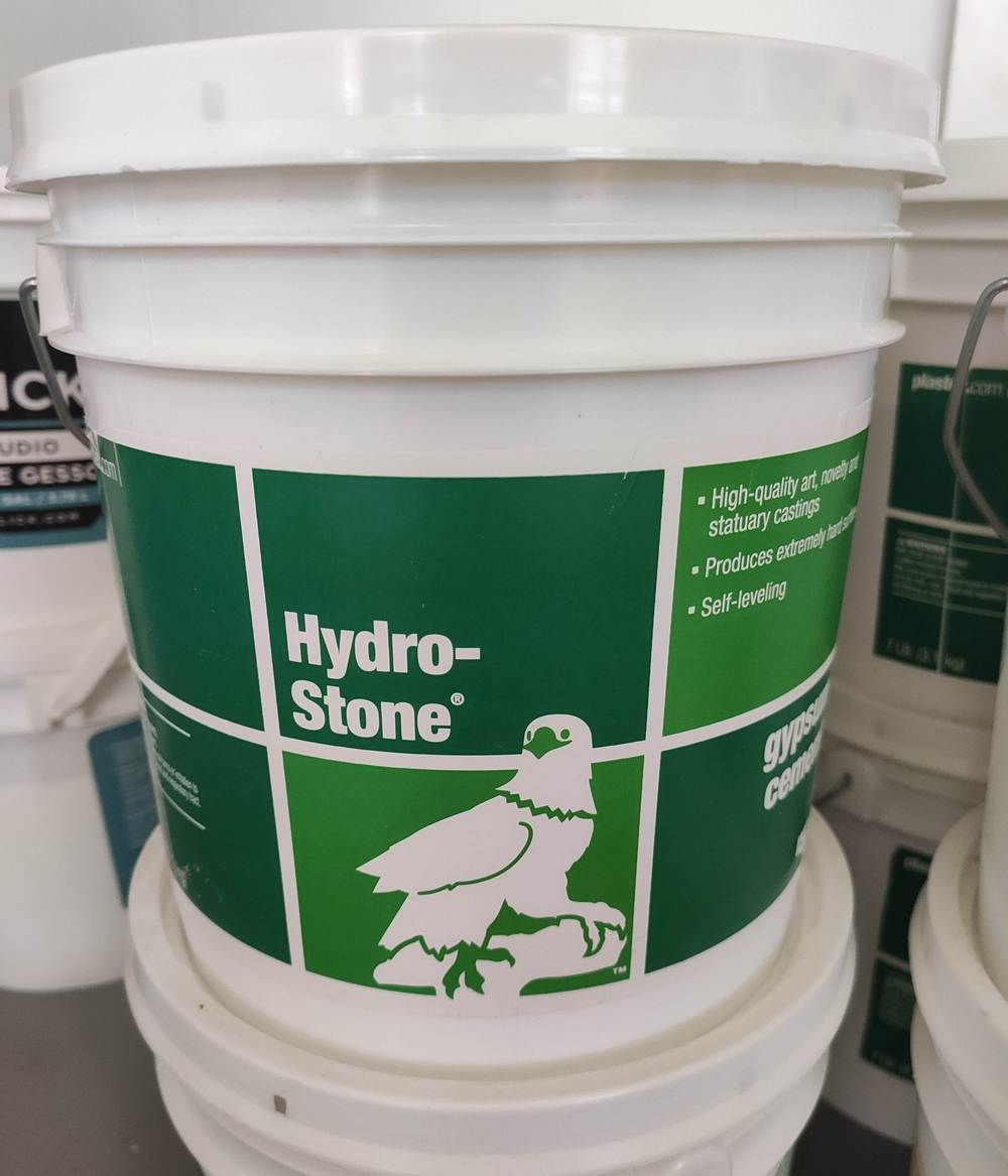
Hydrostone
Hydrostone is a gypsum-cement casting material manufactured by USG. It looks like a white, dry powder, ready to be mixed with water to form plaster.
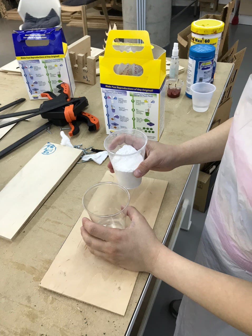
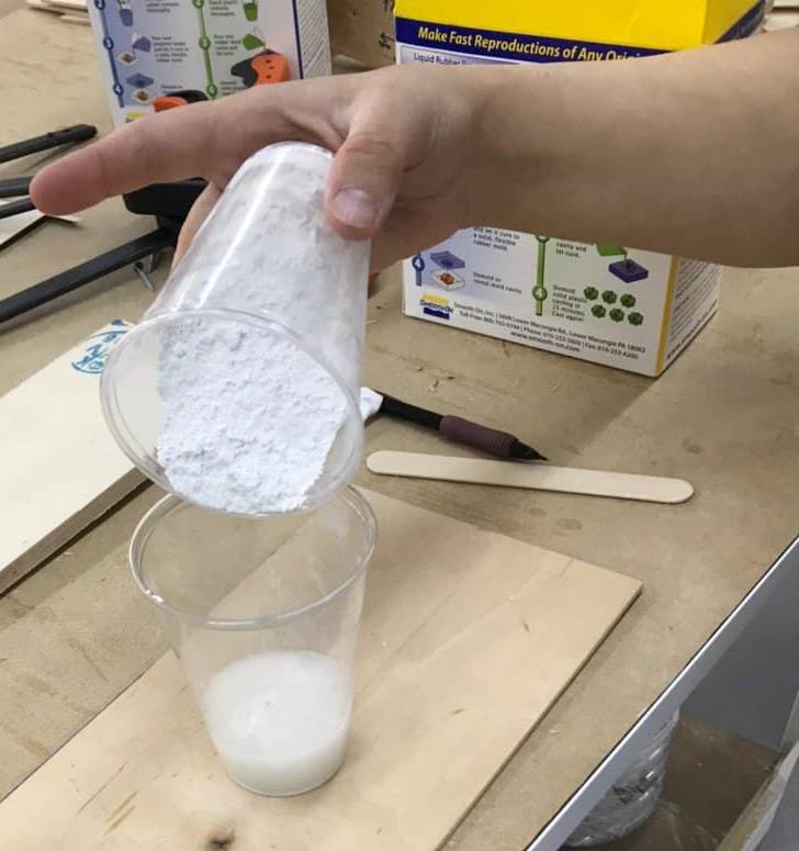
Casting with hydrostone requires a 10:3 product to water mixing ratio by weight. The water should be poured first, and then the hydrostone should be sifted or strewn onto the water slowly, allowing to descend to the bottom of the container as it soaks. It should be allowed to soak for 2-4 minutes.
After soaking, hand mixing will not result in a plaster with the best properties. Therefore, it is preferable to do a mechanical mix with a high-speed, 1750 rpm direct-drive propeller mixer mounted in a stand with mixing shaft set at an angle of 15° from vertical. The propeller should clear the bottom of the container by 1 to 2 inches and the shaft should be about half-way between the center and the side of the container. Propeller rotation should force mix downward. A vortex in the middle of the slurry should be avoided (probably to avoid incorporating bubbles) for 2-5 minutes, depending on the desired properties, as the compressive strength and the set time of the material are a function of the mixing time. The dependency graph can be viewed in the Plaster Mixing Procedures manual of USG.
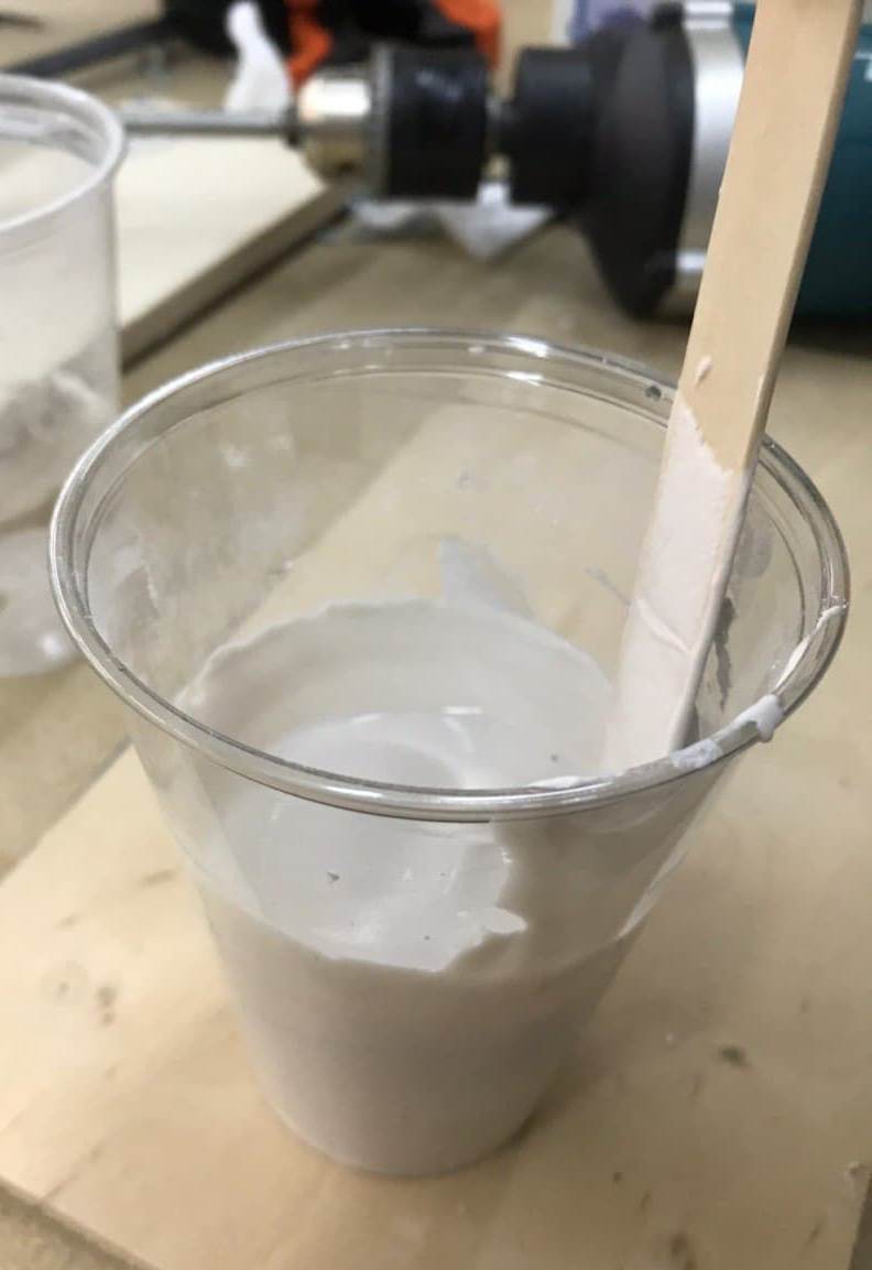
I measured out 49.2 g tap water, and weighted out 153.8 g of hydrostone, for a total of 153.75 g mixture, for both the egg and a test cup. The mixture was soaked, and then mixed using a flat and wide bit inserted in the drill driver.
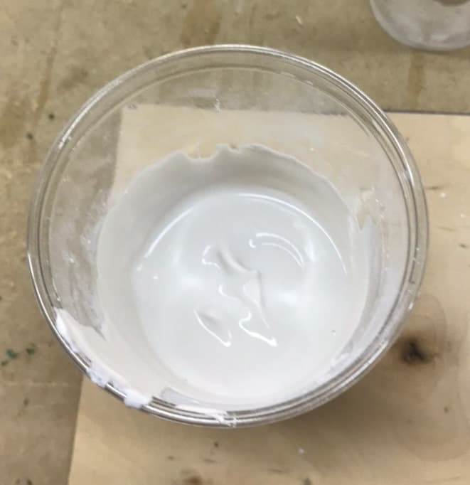
A tongue depressor stick was used to scrape the hydrotone slurry on the walls of the cup.
It seems the hydrostone was mixed a bit too much, as it was very viscous and hard to pour, so I resorted to moving it to the two sides of the mold using the depressor stick:
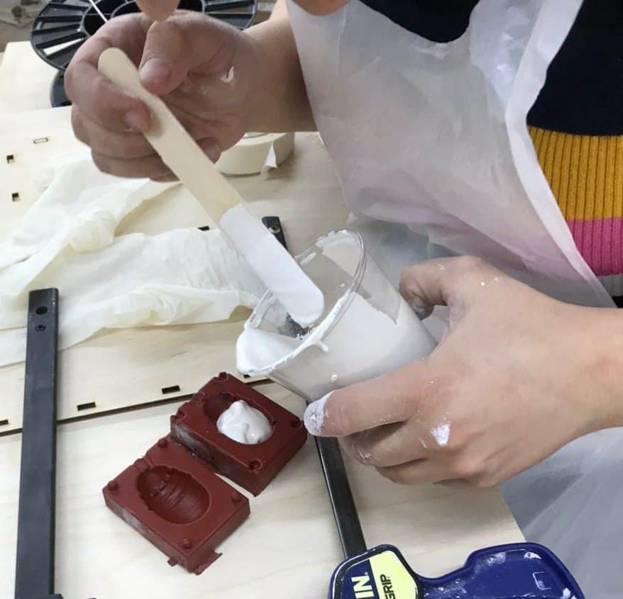
I then brought the two sides of the mold together, and held them so using clamps.
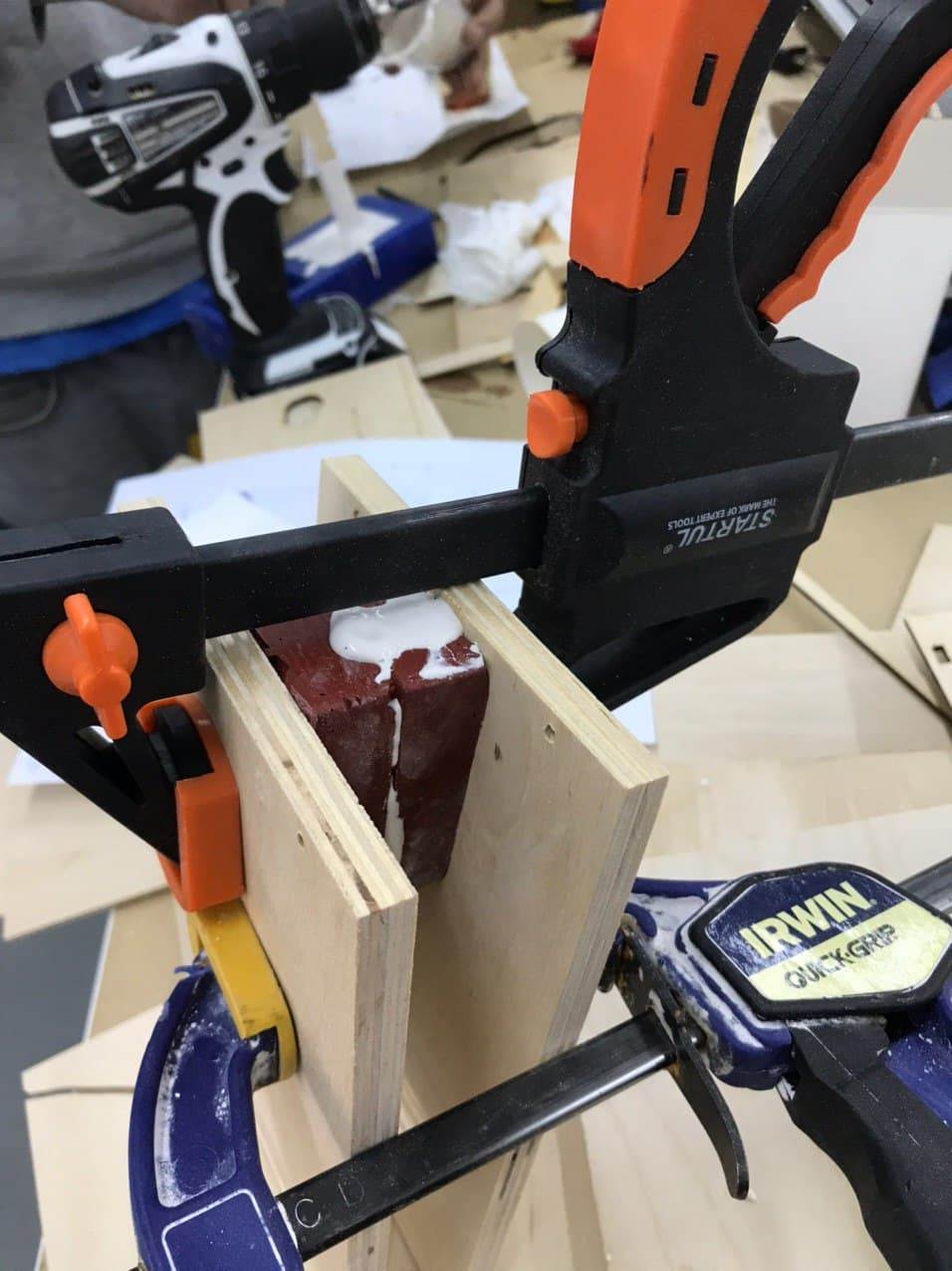
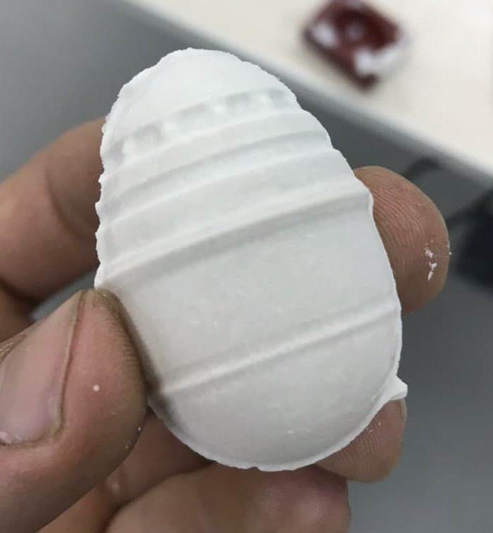
The hydrostone cast dried rather quickly, in a matter of minutes. The final result has some defects/holes in it, probably due to the "pouring" technique -- should probably mix it less next time, or pour it more quickly, before it hardens as much.
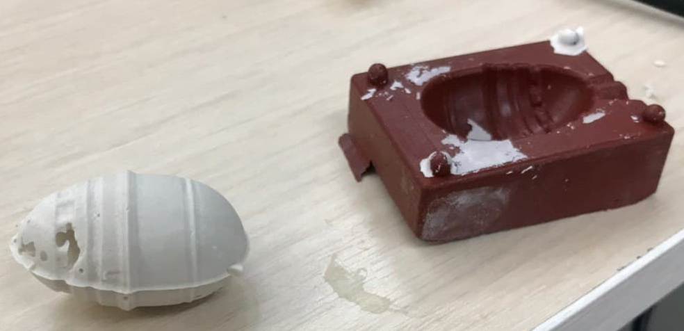
Here is the final result:
Babbitt alloy
And finally, I tried to cast the egg using the Babbitt, a soft alloy, we had in the lab. Since there is no MSDS present with the metal, I can't tell whether it is the tin- or lead-based metal, so I'll be maximally cautious with it.
The only molding material I could use for casting Babbitt was Mold Max 60, since it is highly heat-resistant and can withstand molten metal being poured into it.
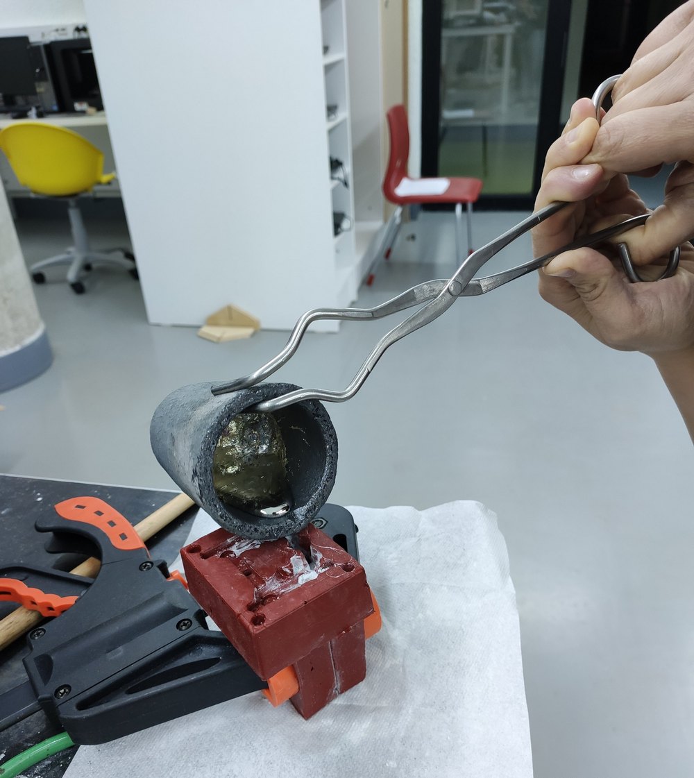
First and foremost, I needed at least one person helping me since I would be dealing with molten metal, an oven to melt the metal, a vessel to melt the metal in, tongues to pick up the vessel, goggles, and heat resistant gloves.
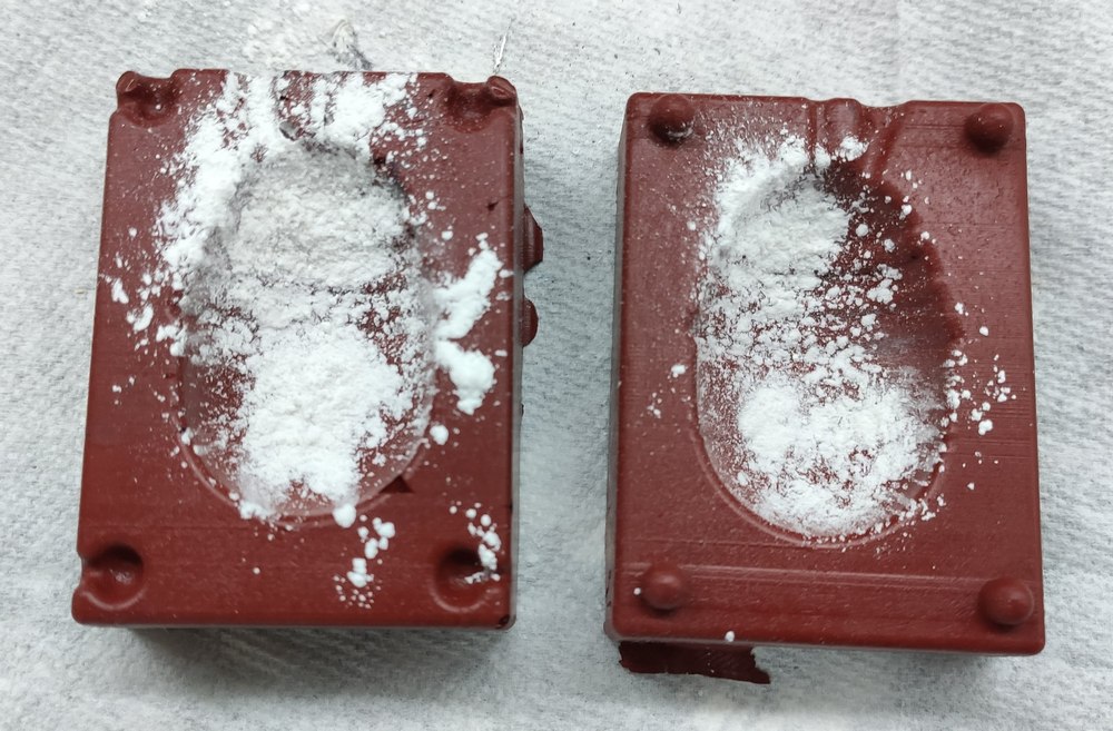
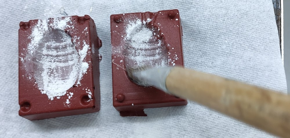
I first washed and thoroughly dried Mold Max 60. I then used talc/baby powder to coat the insides of the mold, as this would prevent bubbles to form on the surface of the metal and give a smoother finish. The talc was brushed in the mold for a thin even distribution.
There was a bit of Babbitt metal left in the lab vessel, so I decided to use that instead of a new bar of the metal. I set the vessel in the oven.
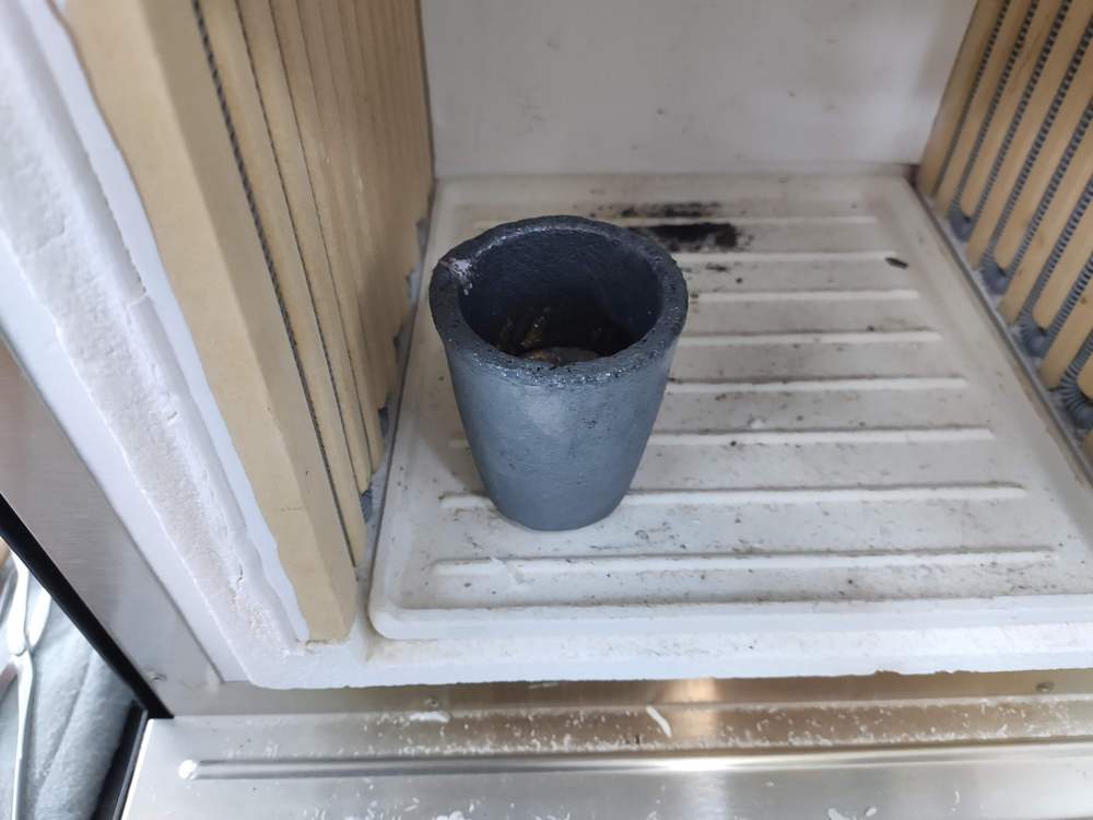
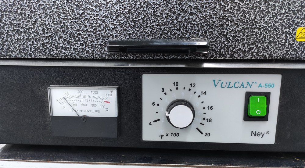
The oven was set to somewhat above 150°C, though this was raised later, possibly above 200°C.
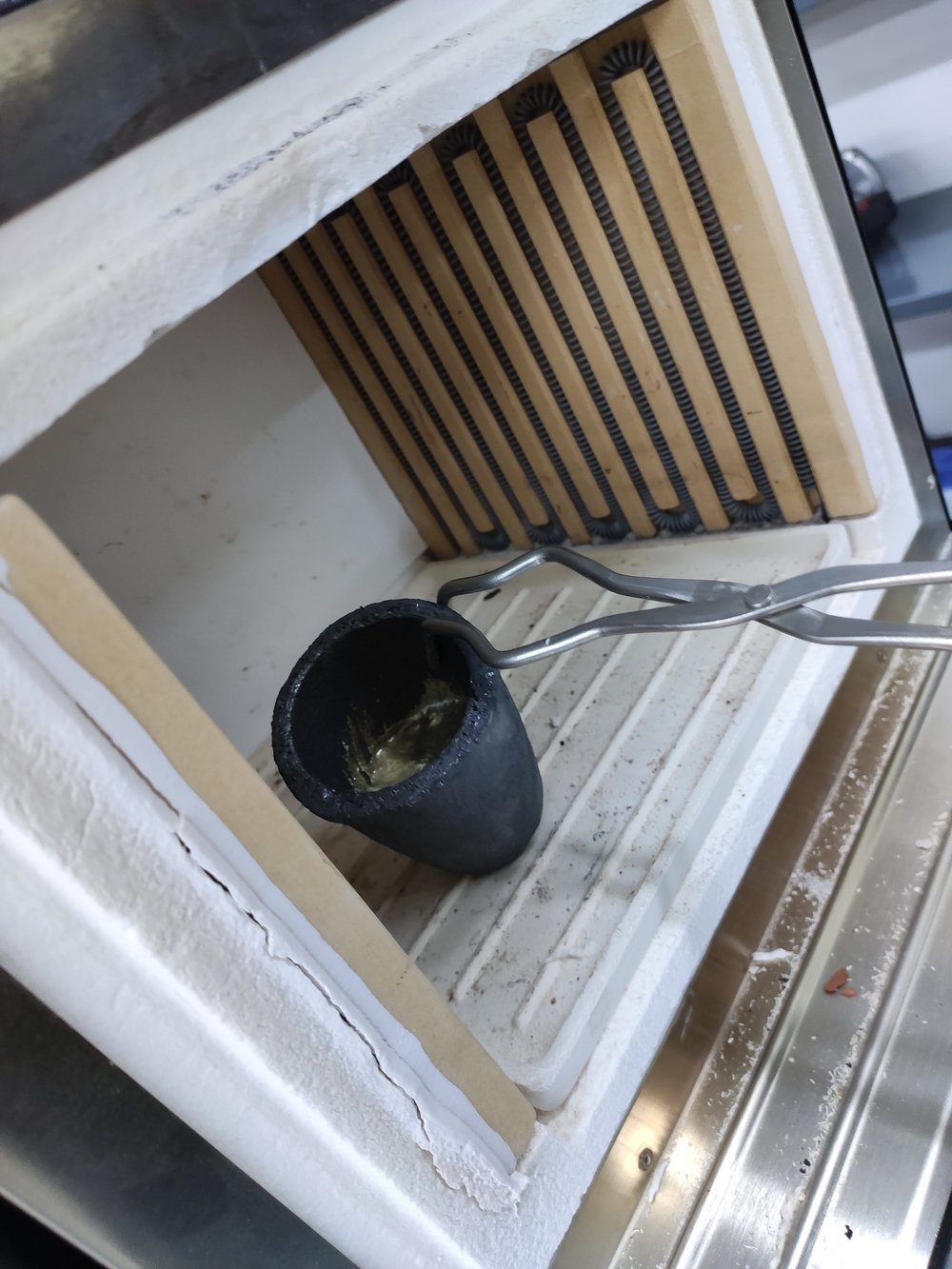
After waiting a few minutes, the metal was molten, and could be poured. The vessel was picked up using tongues.
The talced mold had been prepared for pouring by clamping it together.
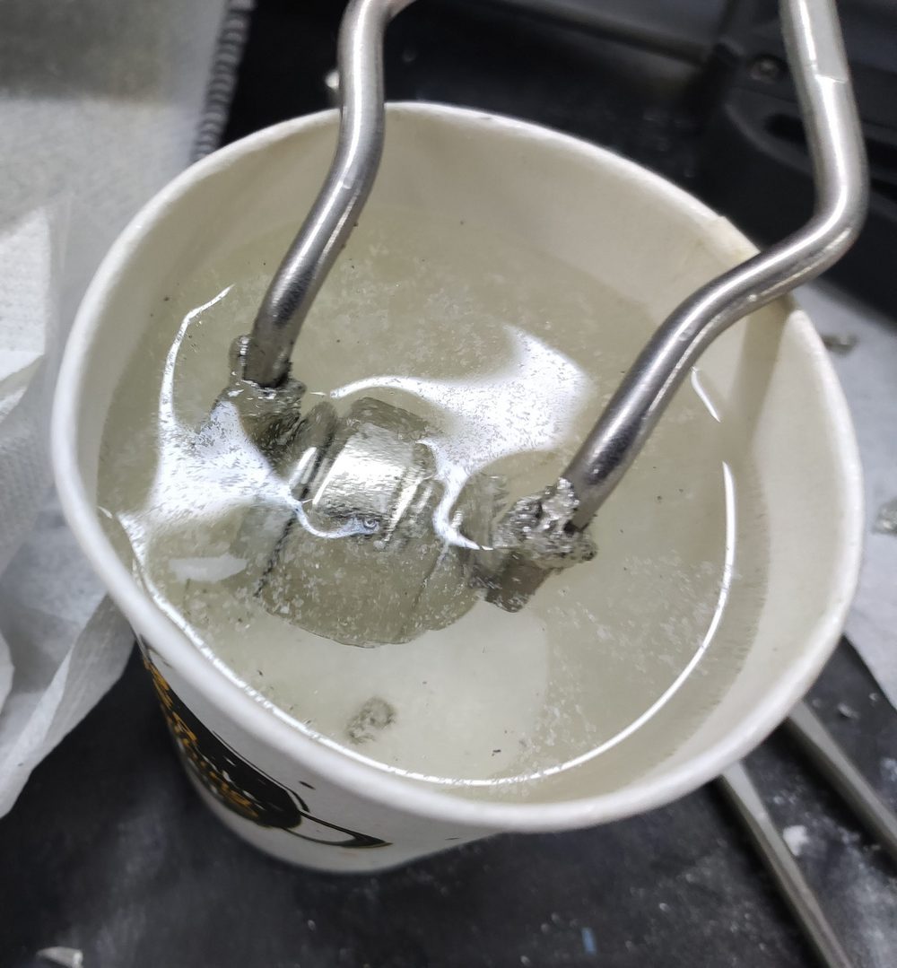
The cast solidified in less than a minute, though to cool it off further, it was immediately inserted into room-temperature water using the same tongues that pulled out the vessel.
Unfortunately, since I had not used a whole bar but what was the remainder in the vessel, the result came out to be half the egg, not the whole one.
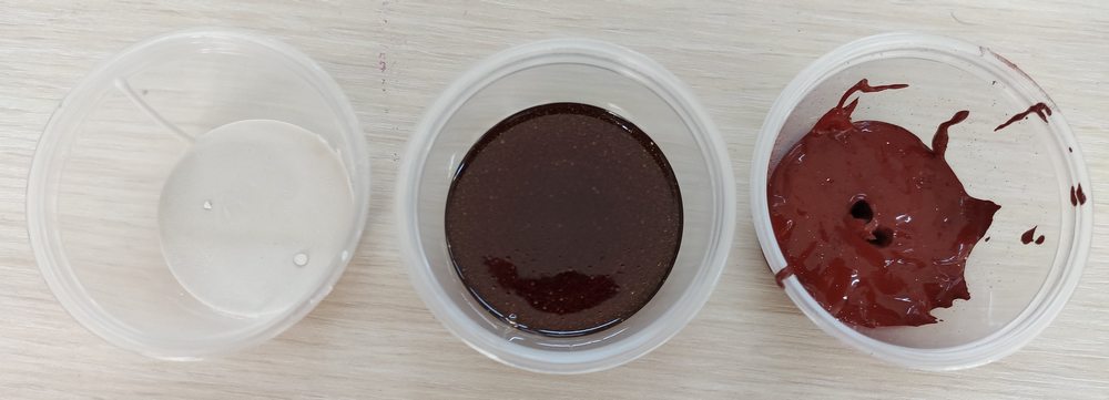
Comparison of the materials used
Here a comparison of the cast materials used can be seen.
From left to right: hydrostone, PMC-121, and Mold Max 60:
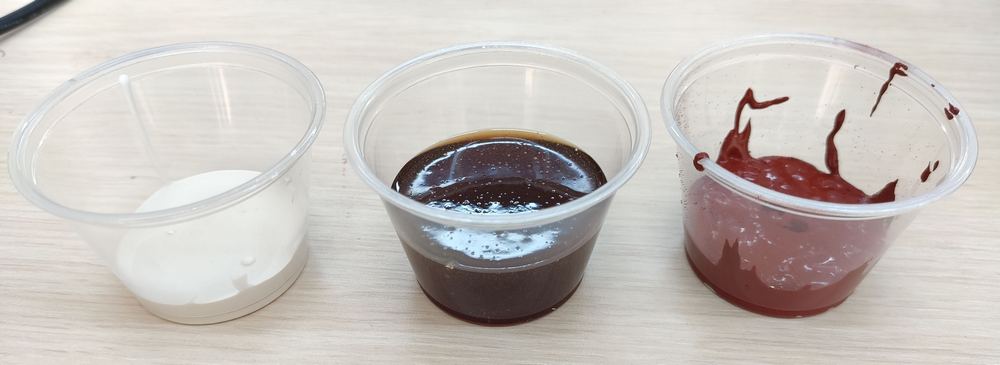
Here are the results in one shot for comparison. The only thing missing is the Babbitt half egg, which was returned to the vessel to be molten and reused -- the beauty of working with metal: almost always reusable.
Comments from Ohad
There were three important comments from Ohad to consider:
Ohad suggested applying turpentine or acetone with a swab for smoothing the surfaces of the wax once it is milled. He didn't recommend heating for that purpose as it could get rid of some features and reduce precision.
Also suggested not using a mold release agent for machinable wax, and also between Oomoo and plaster. In case it was needed, he suggested using sprayed oil.
Make a separate page explaining how to generate g-code from Fusion 360.
Try and do the manufacturing process using completely symmetrical egg halves and therefore using only one mold for mold to generate two mold halves and case the egg. This would cut down on the machinable wax used and would also require a symmetrical sprue and air hole.
Downloading the files
The .zip archive of the files for this week can be downloaded here (2.3 MB). It includes:
- The egg design (Fusion 360 archive file with .f3d extension, 1.2 MB)
- The numerical control code for roughing milling (.sbp, 1 MB)
- The numerical control code for finishing milling (.sbp, 4.8 MB)
Make (almost) anything.


This work is licensed under a Creative Commons Attribution-NonCommercial-ShareAlike 4.0 International License by Maro Aghazarian 2021.