Output Devices
For this week, we had to try using various output devices.
For the group assignment, we had to measure the power consumption of an output device, which can be viewed at the corresponding group assignment page.
Trying to measure the power conumption of an output device is straighforward: One needs to know the voltage drop (V) across the device; if it is the only device connected to a power supply, the supplied voltage would be approximately the voltage drop across the device (ignoring the resistance of the wires); else, it can be measured by a multimeter on voltmeter mode connected in parallel with the output device. The current (I) consumed by the device can also be measured by connecting an ammeter or a multimeter on ammeter mode in series with the output device. Once these two quantities are known, it is just a matter of multiplying them (P=IV) to get the power consumption of the output device.
I initially tried to get a servo motor to work in three different ways:
- Using a power supply and a function generator;
- Using Arduino Uno;
- By designing my own board.
Later, I tried to get an infrared emitter to work.
All of these attemps and journey are documented below.
Servo motor
Here is a brand new HKSCM9 servo motor that I used for the initial part of this assignment.
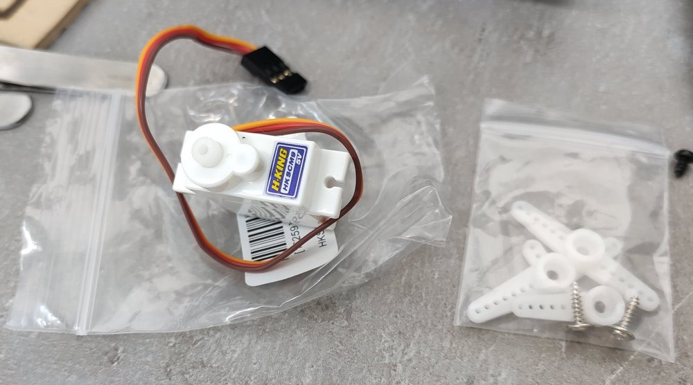
The servo motor takes three inputs through its pins:
- Brown: The brown wire connects to negative voltage supply; we'll be using GND.
- Red: The red wire connects to positive voltage supply; HKSCM9 requires 5V.
- Orange: The orange wire takes the PWM signal.

Theory
A servo motor works by receiving a pulse-width modulation (PWM) is a way of delivering an electrical signal while using less power.
Modulation is the process of converting data into radio waves by adding information to an electronic or optical carrier signal. A carrier signal is one with a steady waveform -- constant height, or amplitude, and frequency.
A PWM signal comprises of a square wave (offset at 0). For a servo motor, the desired PWM frequency is 50Hz. Each cycle of the wave leads with a high section and ends with a low section. The percentage of the duration of the high segment to the low segment is called the duty cycle, and in case of the servo, it determines what angle the servo motor should rotate to.
Using an electrical function generator and a power supply
Our instructor Babken showed me how to use an electrical function generator and a power supply to generate the PWM signal needed to move a servo.
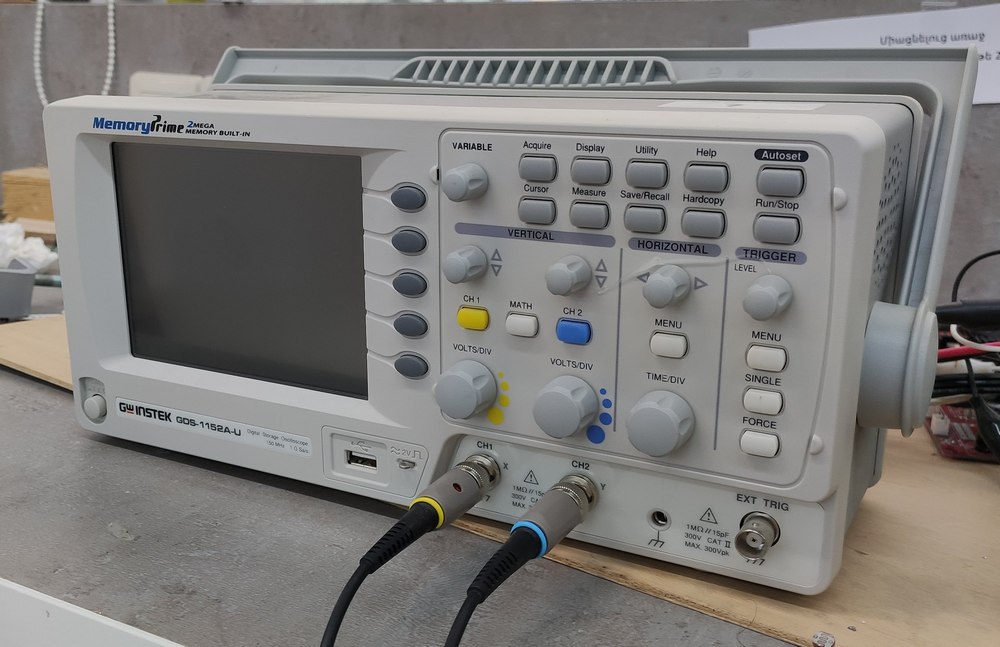
Here's an oscilloscope from the lab that could be used to see the function generated by the function generator:
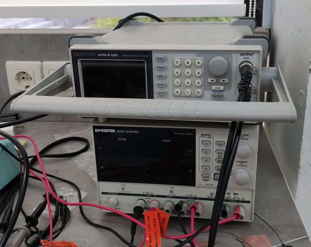
And here are the function generator and DC power supply that were used for this exercise. The power supply supplied 5V and GND to the servo motor, and the function generator was used to generate the PWM signal needed by the servo motor to rotate.
Here's a useful video that explains how this can be attempted:
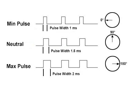
The function generator was used to generate a square wave, where the minimum was offset to zero, and peak-to-peak voltage (Vpp) of 5 V with a frequency of 50 Hz, which would mean period of each cycle being 20 ms.
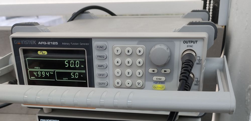
That meant that this servo motor would be updated every 20 ms with a pulse (peak value) between 1 ms and 2 ms, or between a 5 and 10% duty cycle on a 50 Hz waveform. With a 1.5 ms pulse, the servo motor would be at the 90 degree position. With a 1 ms pulse, the servo would be at the 0 degree position, and with a 2 ms pulse, the servo would be at 180 degrees. The rest of the angles could be obtained by values of duty cycle in between.
The function generator was used to change the percentage of the duty cycle, and the following video shows how the servo moved with the changes in the duty cycle:
Using Arduino
Next, I wanted to try using an Arduino Uno to move the servo motor.
Getting a servo motor to work with an Arduino is explained very clearly in this 3 min video:
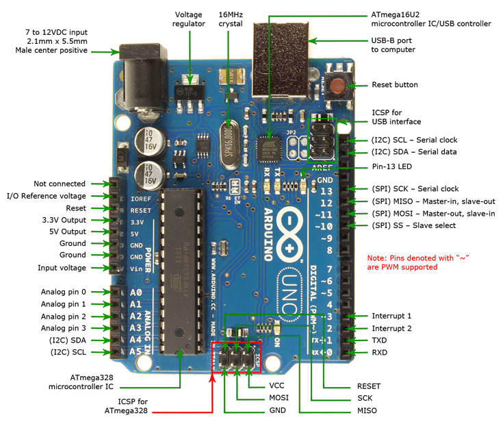
Here is the pinout configuration of Arduino Uno; as can be seen, the pins that can be used for PWM signals are marked with a tilde (~). I decided to use pin 3 as my PWM pin of choice:
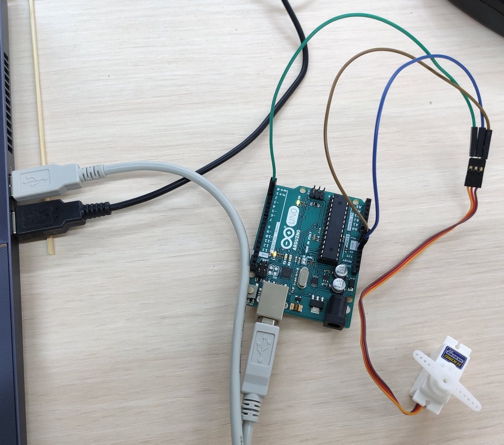
Here's how the servo was connected to the Arduino Uno: using a 5V pin, a GND, and pin 3 for PWM. The Arduino Uno was also connected to the computer using a USB B to USB A cable, which also requires 5 V and would be used for programming the Arduino Uno:
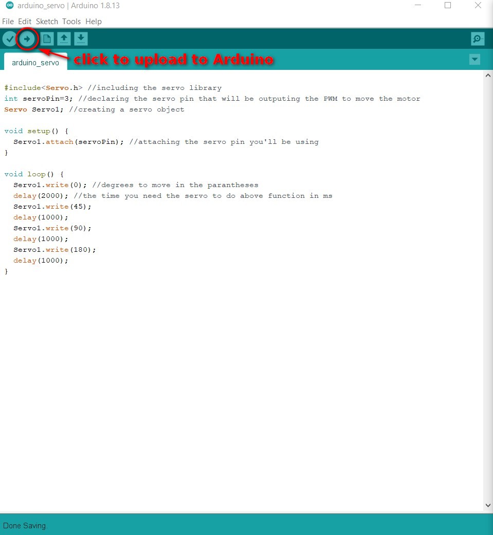
Once connected, the following .ino code was created; it should be mentioned, once more, that the Arduino .ino files use C code with Arduino libraries. The following code uses the Servo.h servo library.
                #include <Servo.h> //including the servo library

                    int servoPin=3; //declaring the servo pin that will be outputing the PWM to move the motor

                    Servo Servo1; //creating a servo object


                    void setup() {

                    Servo1.attach(servoPin); //attaching the servo pin you'll be using

                    }


                    void loop() {

                    Servo1.write(0); //degrees to move in the parantheses

                    delay(2000); //the time you need the servo to do above function in ms

                    Servo1.write(45);

                    delay(1000);

                    Servo1.write(90);

                    delay(1000);

                    Servo1.write(180);

                    delay(1000);

                    }
In order to upload the code to the Arduino Uno, the correct board, port, and programmer had to be selected under
Tools in Arduino; the 'Board' was set as 'Arduino Uno', the 'Port' from which the USB is connected would
have to selected as well (whenever in doubt, check the Device Manager of Windows to know which
port the USB is connected to), and the 'Programmer' was set as "Arduino as ISP" (ISP stands for in-system programmer).
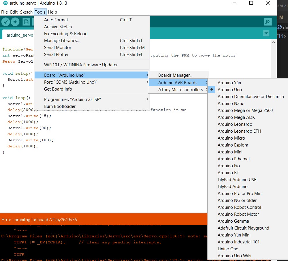
Once the correct settings were in place, the 'upload' button could be click to compile and upload the program to the ATmega328P microcontroller of the Arduino Uno board, which would then be able to control the rotation of the servo:
As can be seen in the following video, things went smoothly and the servo motor rotated according to the program:
Using own PCB
The way I went about this was by looking at Neil's servo board using ATtiny44 and trying to recreate the same logic for ATtiny45.
I had a lot of trouble finding out which 5V regulator we had at the lab, as searching by 'LOB' written on it would not give me any results. Finally had to look at the inventory page and try to guess which one of the 5 regulators listed at the Fab Academy's inventory:
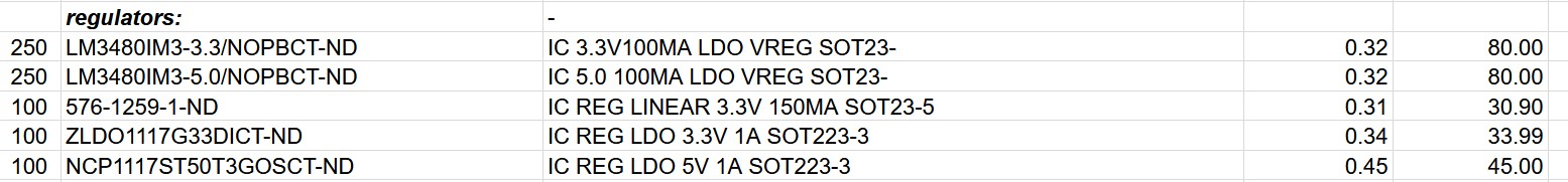
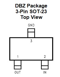
I found out that it is probably c (LM3480IM3-5.0/NOPBCT-ND) by TI. While searching, I also found out that TI and Microchip have different logic in terms of which pins (output, input, GND) are located where. In case of the 3-pin quasilow-dropout linear voltage regulator, this is how the pins are configured:
The crystal oscillator we had available at the lab was NX5032GA (20MHz, 8pF), so I'm thinking this would be the datasheet.
Quartz crystal resonators and ceramic resonators activate and work similarly as they both vibrate mechanically when an AC signal is applied to each respectively. The difference is that a quartz crystal resonator is made from a quartz crystal and a ceramic resonator is from ceramic components.
After spending waaaaaay more than I should on trying to find the footprints for the LM2490 regulator, or any other regulator with the same footprint, or creating one, I came to the conclusion that the best course to follow would be downloading the Fab library for KiCad, which I should have perhaps done earlier :)
Keeping 'better late than never' in mind, I proceeded to follow these instructions and download the KiCad Fab library from here and imported it into KiCad per the instructions.
Finally, I came to realize the regulator that I'm going to use is actually NCP1117, which I could find the footprints for, expect didn't have a footprint for the tab.
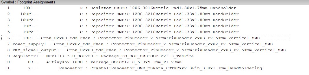
I could finally find out which were the components we had at the lab and the appropriate footprints:
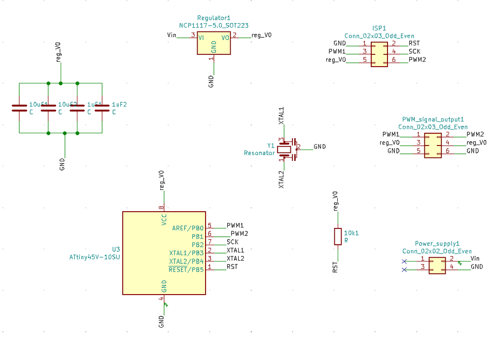
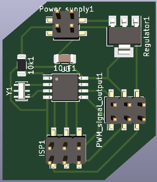
And here's how the final schematic diagram for my ATtiny45-controlled servo board designed with KiCAD looked like (for more on how to design with KiCAD, check out theelectronics design week):
From there, I generated netfiles and imported them to the PCB design section of KiCAD. After setting rules of track width (trace width) and clearance of 0.4 mm, I set out to define the one layer of traces without overlap. Once more, I believe the tracing is the hardest part of the PCB design, and probably should be taken care of with an autotracing program using graph theory, etc.
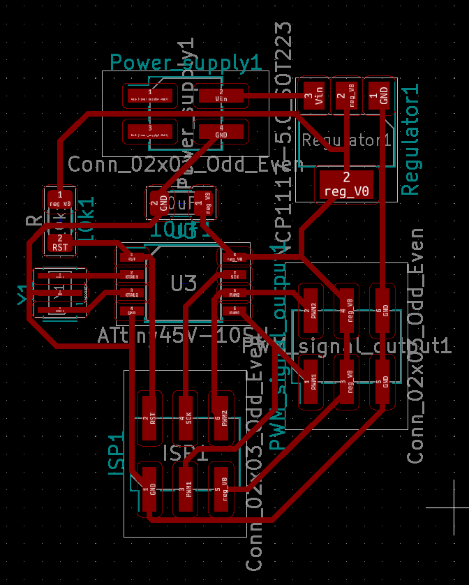
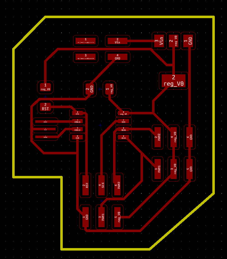
Here the edges of the board are also included with the design, and it seems I've left the default width of 0.4 mm for the edges, while for the edges I usually define the rule of 0.8 mm thickness:
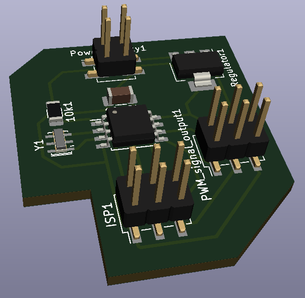
Here's the 3D visualized version of the board using KiCAD's Pcbnew (go to View --> 3D Viewer):
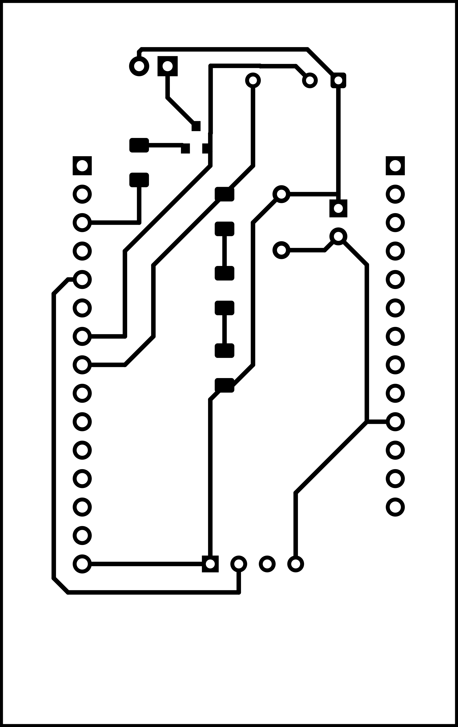
From here on, I exported the traces and the edges separately as a monochromatic .png with 1000 dpi, opened them with GIMP, and tried to make sure the files are of the same size, and the outline around the edges is changed to black, while the edge itself is changed to white (as fabmodules generates the milling g-code such that the black edges are milled and the copper on the white areas remains). The g-codes were then generated using fabmodules, with the number of offsets set to 4, which determines how many times the bit will trace around each path. For more details on how to manufacture the board, see the electronics production week.
This time around, I had quite a bit of problem milling the board. No matter how much I tried, the board would come out more 'polished-looking' that milled:
>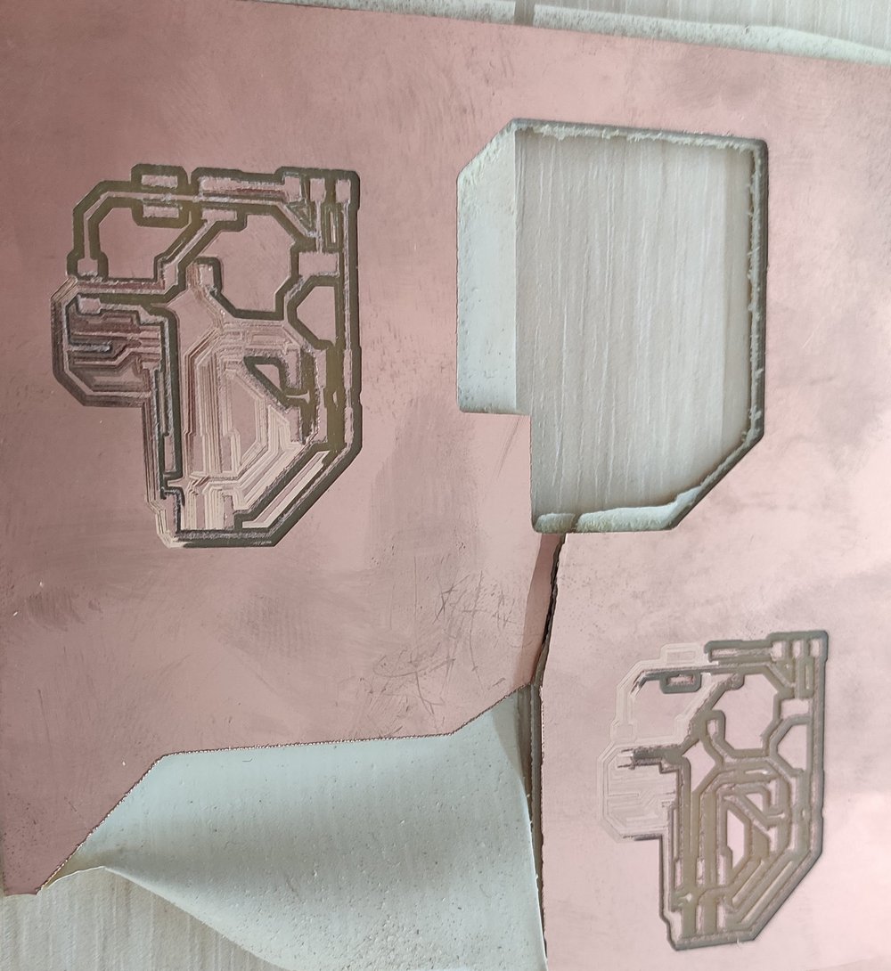
I tried changing the board and clamping it longer before setting it up, thinking the board might be warped:
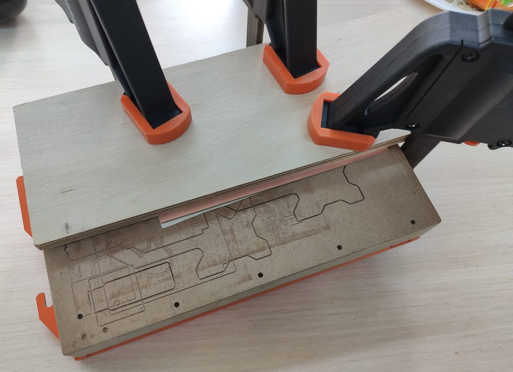
But that wasn't the case. In fact, it wasn't until next week that I discovered the problem was the milling bit; perhaps it was too worn, or it had been damaged. But changing the bit to a new one was what solved the problem.
I then proceeded to solder the components to the board. Here are the components that were used:
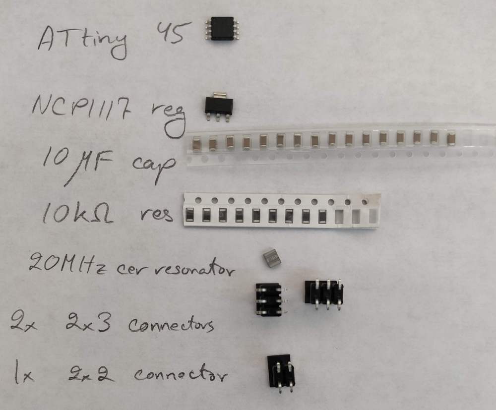
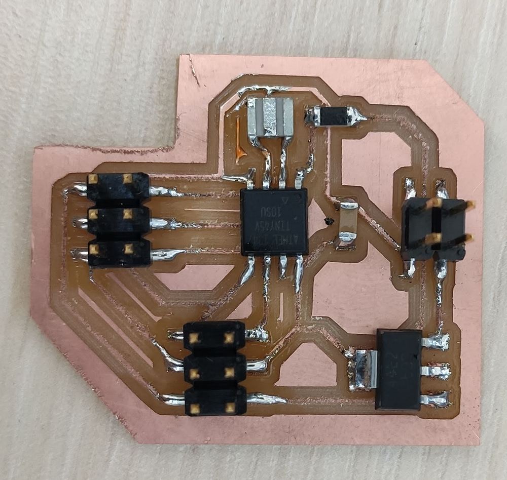
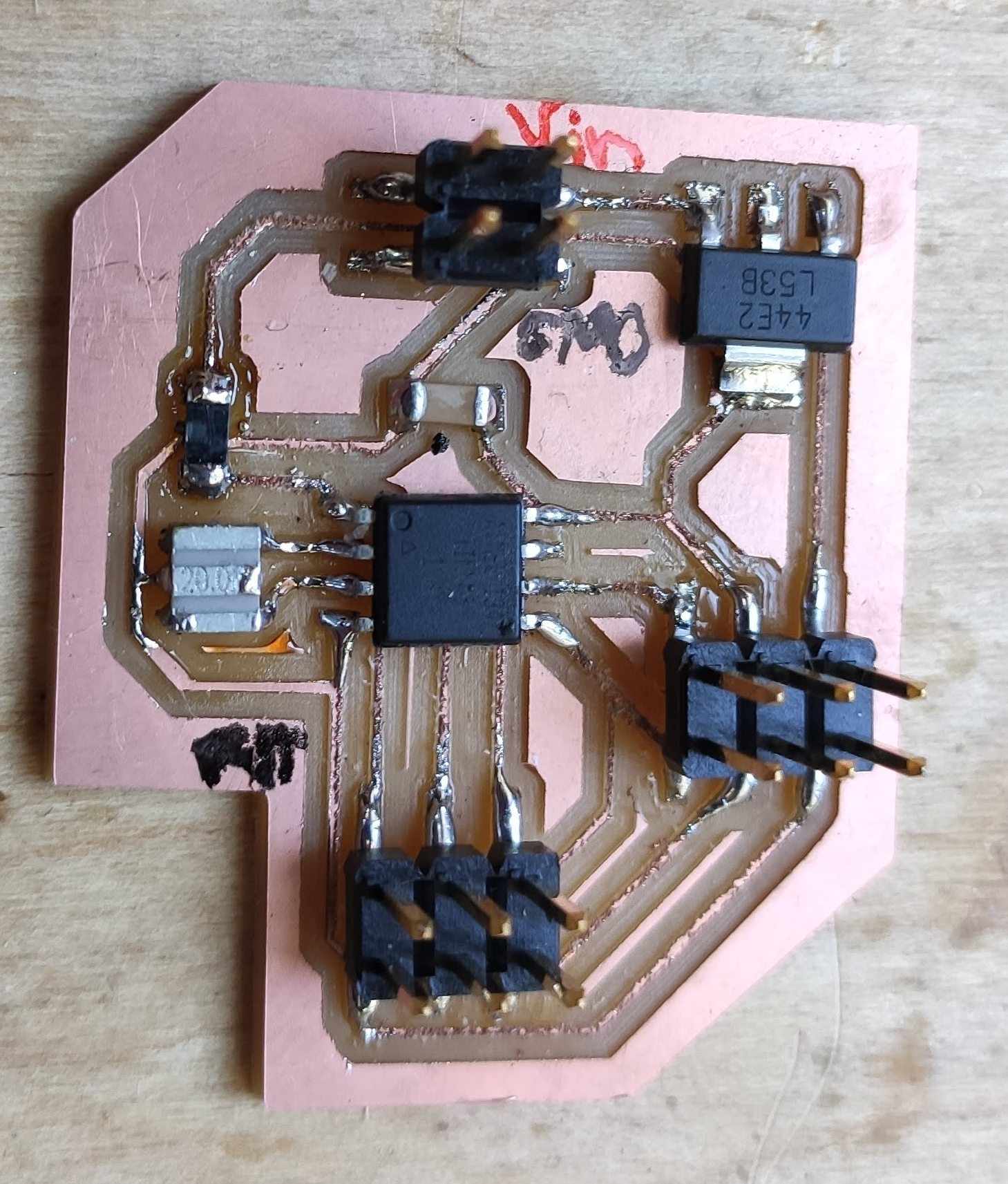
And here is the final soldered board, milled with the old bit, which can be seen from the jagged edges. At this point, I didn't know that I can smoothen its surface by gently sanding with a 500 grit or higher sandpaper, without actually damaging the thin traces (Attention: ATtiny45's dot points to the RST pin.):
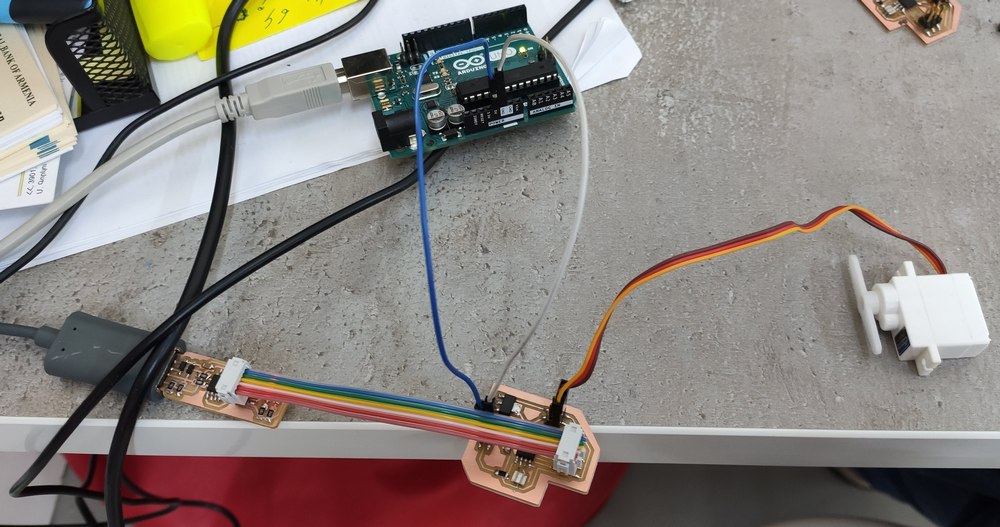
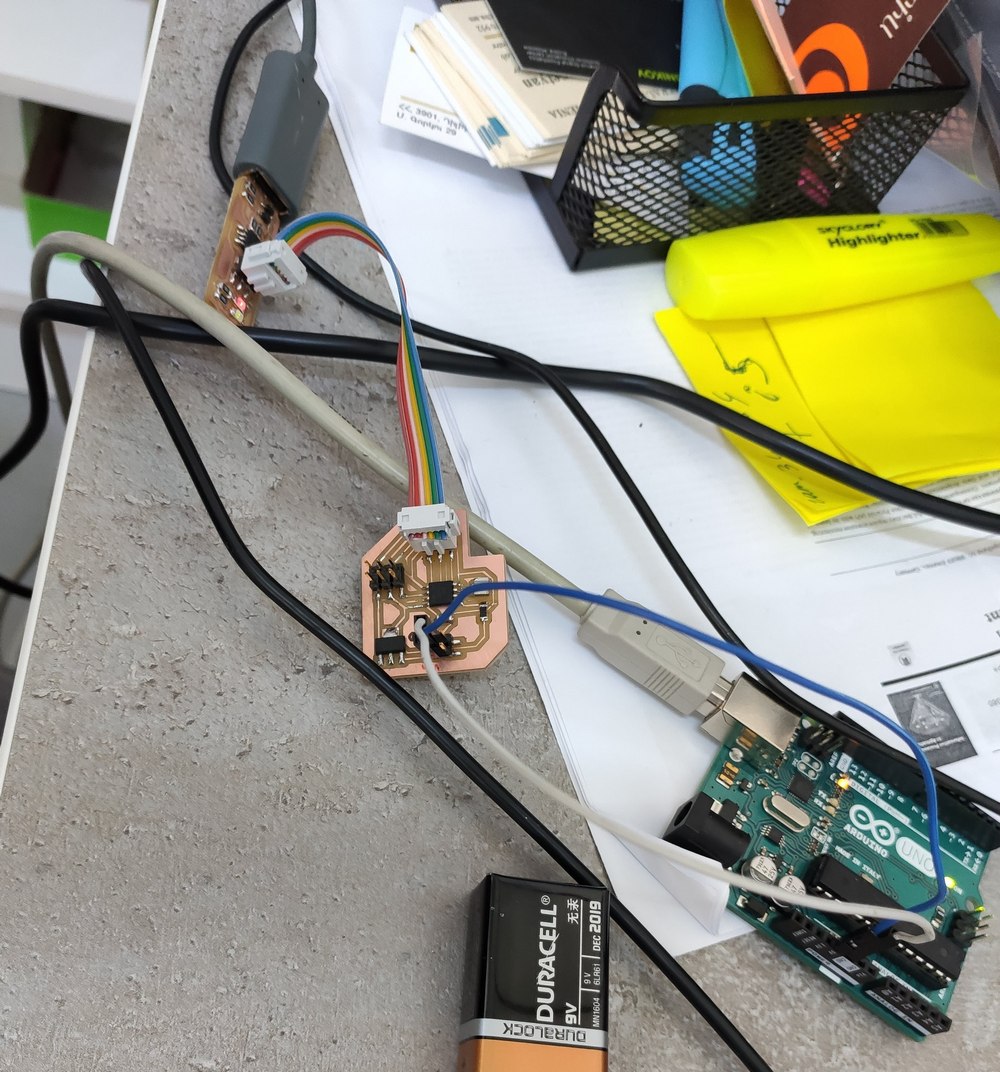
The board was then connected to the FabTinyISP (programmer) and the servo, and since it required 5V to operate (which could not be provided through the programmer, eventhough it does have a VCC pin), it was powered up by connecting to the 5V pin of the Arduino Uno. The FabTinyISP itself was connected to a Linux computer to program with a servo program written in C (modified for ATtiny45). The program was compiled using the appropriate makefile. For more on the programming details, see the embedded programming week.
And then the struggle with programming it started. Initially, I would just get errors trying to program it. After checking out the traces using a multimeter, I found an error: the GND trace passing underneath the 10 kΩ resistor was touching one of its sides connected to the reset (RST) pin of the ATtiny45, effectively grounding the reset pin. I procedded to desolder the resistor, and lo and behold, there was the short between GND and RST:
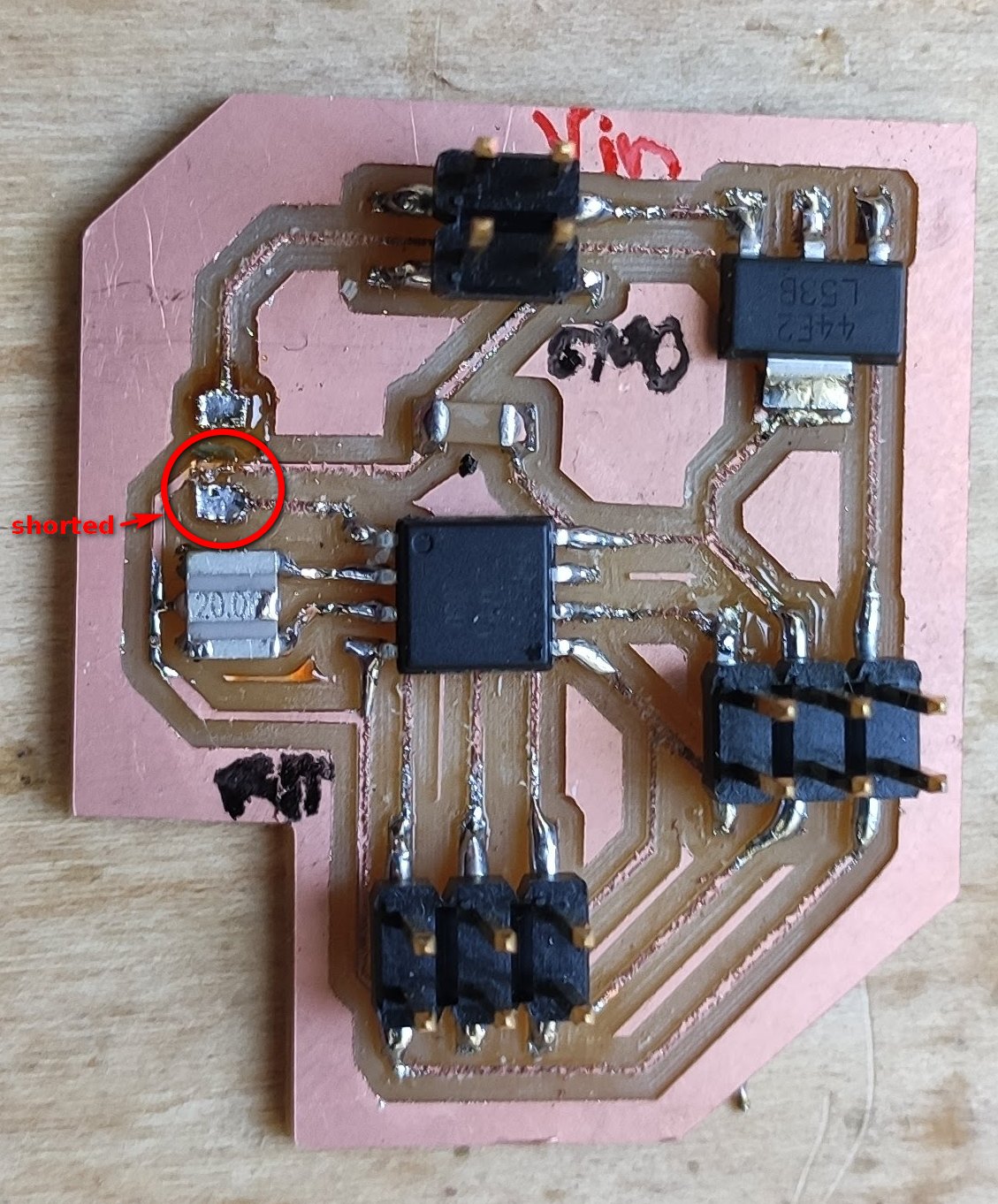
I solved the problem by using an x-acto knife to remove the copper in between, and soldered the resistor back on:
And then tried to program the board again. But only more errors. until Babken noticed that I had connected the FanTinyISP to the board wrongly. So I changed the configuration, making sure the pins were connected correctly, and tried again:
But I got more errors still. So this was left for later to try once more to figure out why the board could not be programmed.
Infrared emitter
On week 13 and week 14 I worked on creating a universal remote control board using NodeMCU (with ESP8266). I have there documented how to set up and use an infrared emitter as an output device, which was used for controlling remote-controlled devices. All the steps and the design of the board have been explained in those weeks. The files are once more available for download at the bottom of the page.
Downloading the files
Servo board
The files for the servo board can be downloaded here:
- The schematic of the board (KiCAD schematic file with .sch extension, 34.1 kB)
- Monochromatic image of the traces of the board -- should be inverted for milling (.png, 3.27 kB)
- Monochromatic image of the outline of the board (.png, 868 B)
- The Arduino program for the servo (.ino, 538 B)


Infrared emitter board
The files for the NodeMCU remote control board can be downloaded here:
- The schematic of the board (KiCAD schematic file with .sch extension, 47 kB)
- Monochromatic image of the traces of the board -- should be inverted for milling (.png, 133 kB)
- Monochromatic image of the outline and holes of the board (.png, 72 kB)