3. Computer Aided design
This assignment draw two parts of the robotic arm aimed as a final project in the FabAcademy. The first object represents the base of the arm, where it will be attached the servos that will move the arm. The secont object is the parts that will enable up-down and front-back movements of the arm. The first object will be designed using Fusion 360 and Onshape. The second one will be designed using Inkscape. The draws are prototype of the arm and can change when the project advances to adapt for important functionalities.
Fusion 360
To help how to design the robotic arm using Fusion, it was used the following two tutorials. The first tutorial explains the basic functionalities of the tool, how to create sketch and objects (watch the video here). The secont tutorial also explains some functionalities of the software, but I was interested in the explanation of how to use parameters (watch this video from 8 minutes). I also got help from a collegue that know better the tool and could give some important tips that enable me to design the following steps. Following, the steps taken to design the base object for a robotic arm:
-
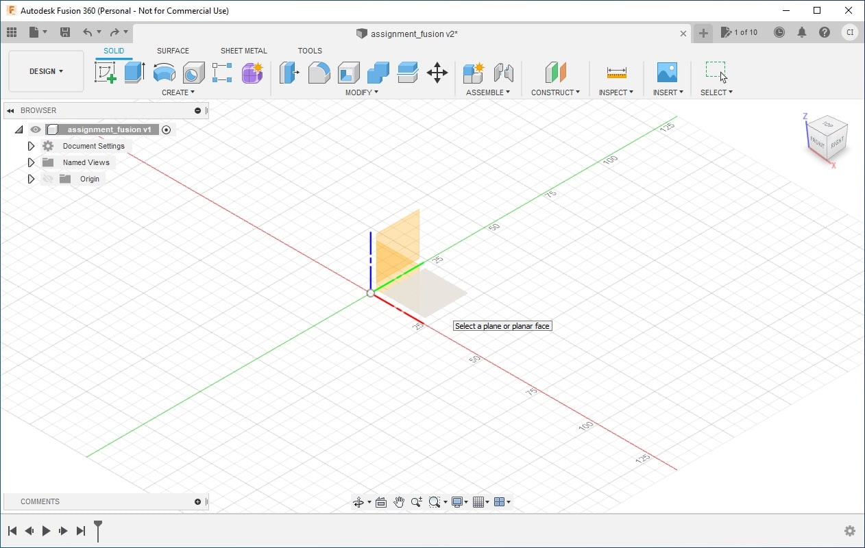
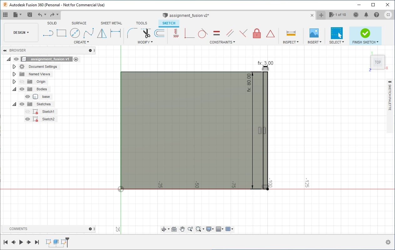
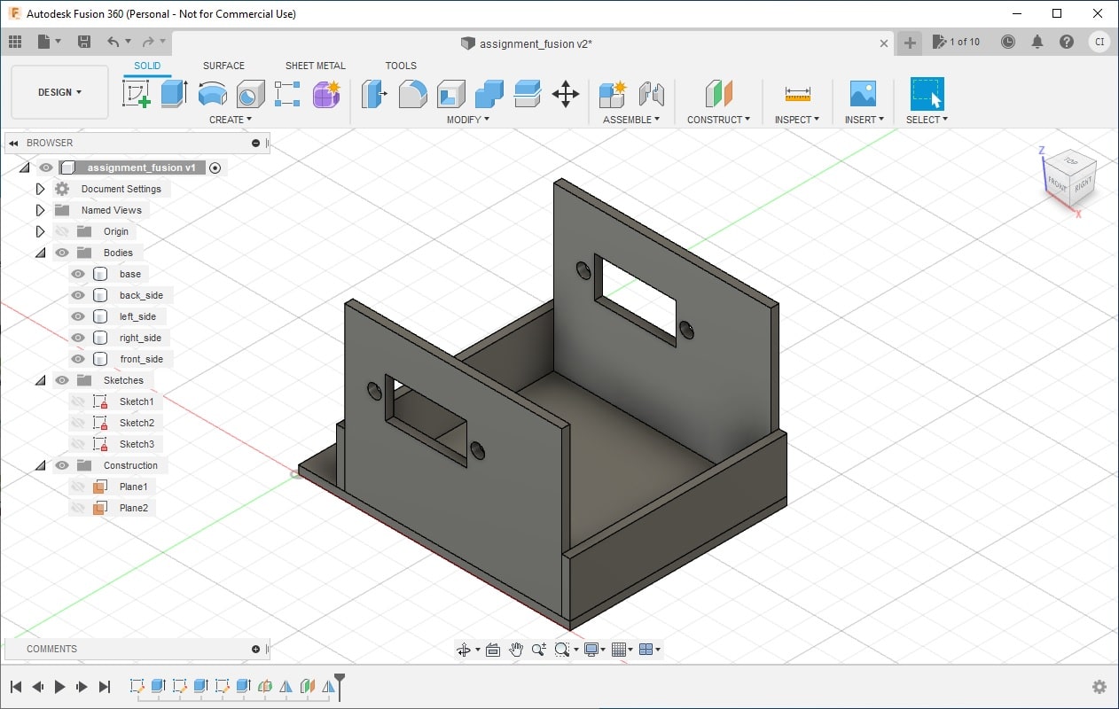
this is the initial window of fusion. On the top bar you can find all available menus. in the bottom of the window you will find each step taken to design your object.
-
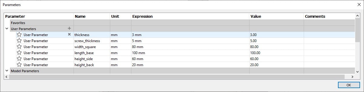
First add all necessary parameters. The parameters allow you to adjust the dimensions of your design without the need to change each part you create. You can change the parameters using the menu MODIFY > Change Parameters in the initial page of fusion. In my drawing I needed the (i) thickness of the marterial to be used (3mm); (ii) the screw’s thickness (screw_thickness = 5mm); (iii) the width of the square to place the side parts (width_square = 80mm); (iv) the length of the base (length_base = 100mm); (v) the height of the left and right side part, where will be attached the servo that will controle the robotic arm (height_side = 60mm); and (vi) the height of the front and back sides (height_back = 20mm). The dimensions were choosen based in a small prototype of the arm to be used as proof of concept. Once complete, the parameters will be adjusted according to the required size of the arm.
-
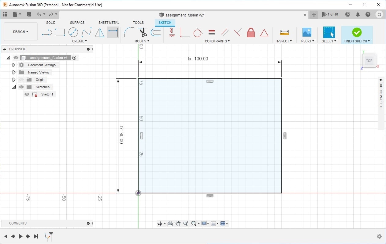
In the initial window of fusion, select the menu CREATE > Create Sketch. Choose the plane where you desire to draw. I have choosen the plane XY (plane created by the axis X and Y in the space). I will design the base object of the robotic arm, so I choose the square in two points and set the parameters length_base and width_square to make the size of the base easily adjustable.
-
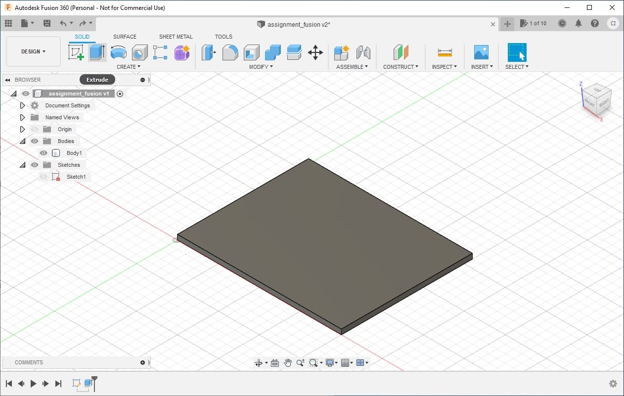
From the sketch, you can create the part that will represent the base of the object. In fusion each part is called body. Select the menu CREATE > Extrude and choose sketch drawn in step 3. Set the thickness of the base using the parameter thickness. This create the first part of the object.
-
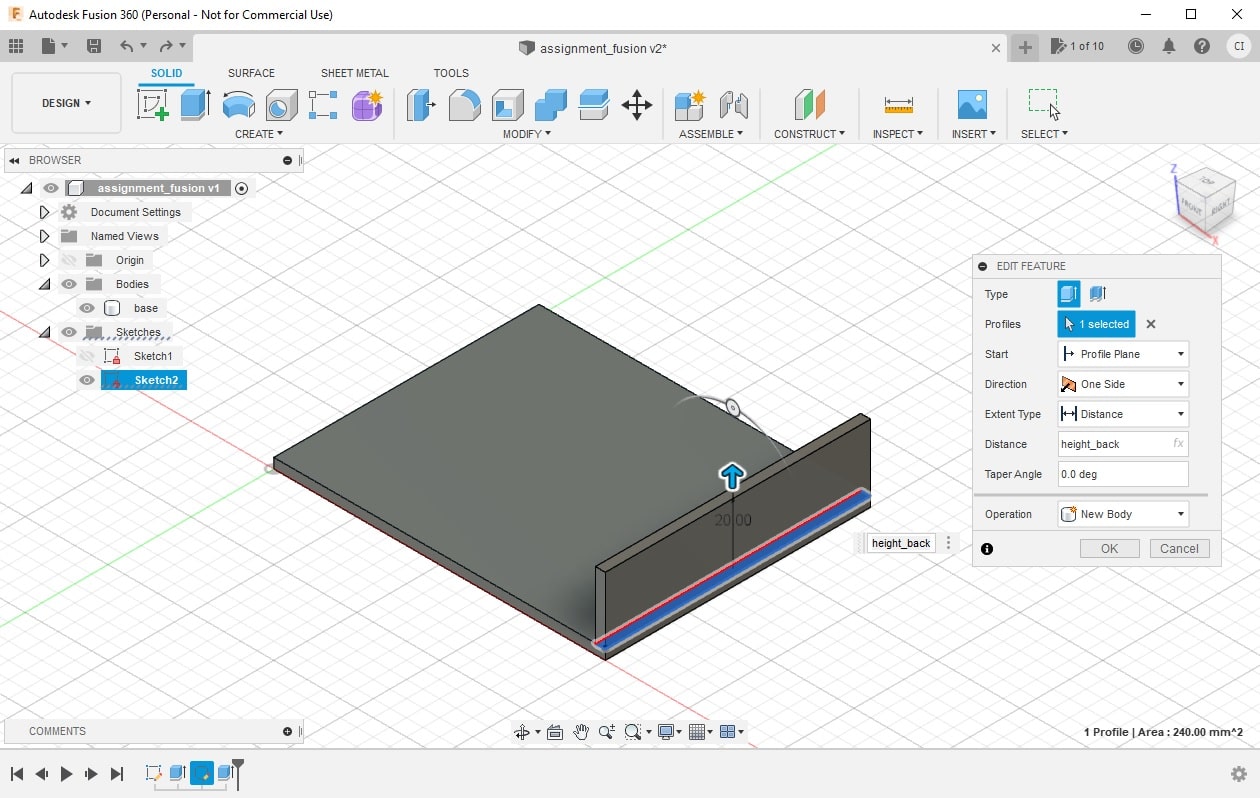
To create the back side of the object, select again Create Sketch and choose the top plane of the base create in the step 4. Draw again a square in two points assigning the dimensions thickness X width_square. Make the right line coincident to the back side of the base. Select both lines, from the sketch and the line of the back side of the base, and select the menu CONSTRAINTS > Coincident.
-
Create the extrude for the back side of the object. Select the menu Extrude and choose the sketch created in step 5. Set the distance of the extrude using the parameter height_back. An important step for this extrude is to select its correct Operation. If you want to create one single body using the back side, select the operation Join. I used New Body because I want to create independent parts for this object. This way this drawing can be used for a 3D printer model but also for a laser cut model.
-
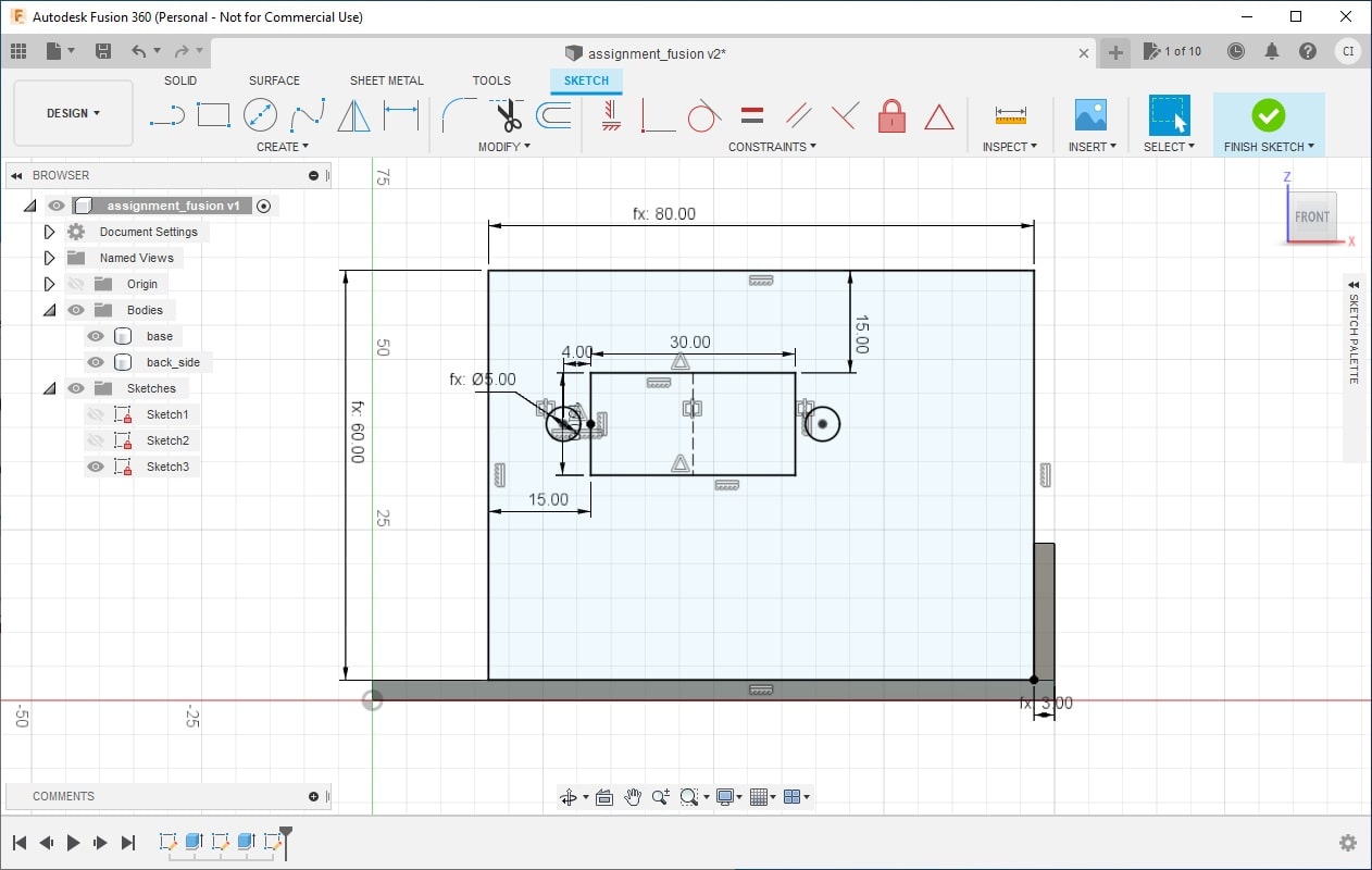
Create a new sketch for the side part of the object. Select the menu Create Sketch and choose the side plane of the base (the one created by the thickness of the extrude). This sketch need to be in a vertical orientation because it will contain the hole to attach the serve that will move the arm. Draw one square in two points and set the dimensions width_square X height_side. Draw a smaller square inside the big one with the dimension 15mm X 30mm. This dimension can be parametrized as well, to make easy for this assignement, this step was skiped. Set the position of the small square related to the big one. Select the menu CREATE > Sketch Dimension, choose the upper line of both squares and set the distance (15mm). Do the same for the left side of the square, menu Sketch Dimension, select the left lines of the squares, set the distance (15mm). Draw one circle and set the dimension to screw_thickness. Add a construction line in the middle of the small square (draw a line in the middle, rigth click in the line, select menu Normal/Construction). This line will not be considered in the sketch and it will be used for reference purpose. Create a mirror of the circle using the construction line you added. Set the distance of the circle and the small square (4mm). Add a point in the middle of the left line of the small square. Make the center point of the circle and this point coicident (select both points and use the menu Coincident).
-
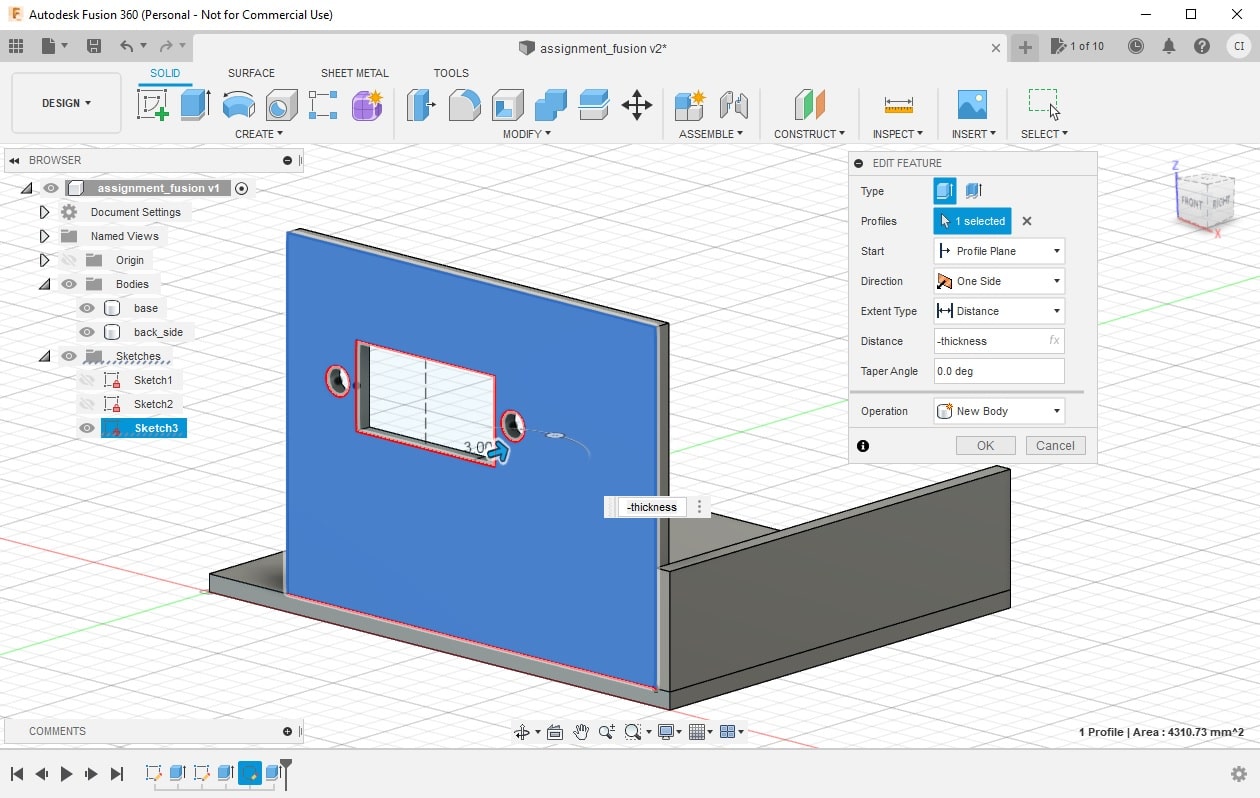
Add a new extrude for the sketch draw in the step 7. Select the menu Extrude and choose the sketch. Adjust the distance of the extruder to -thickness. Notice that you need to use the operator minus (-) in order to include the part of the object aligned to the base part. Again, the operation choosen is New Body.
-
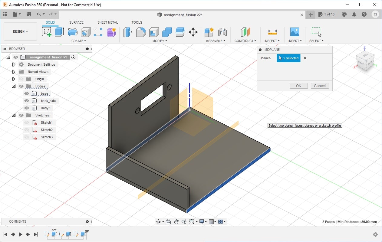
Add a middle plane in the base using the menu CONSTRUCT > Midplane. You need to select two planes that will be the reference for the middle plane. Select the sides of the base created by the thickness of the extrude.
-
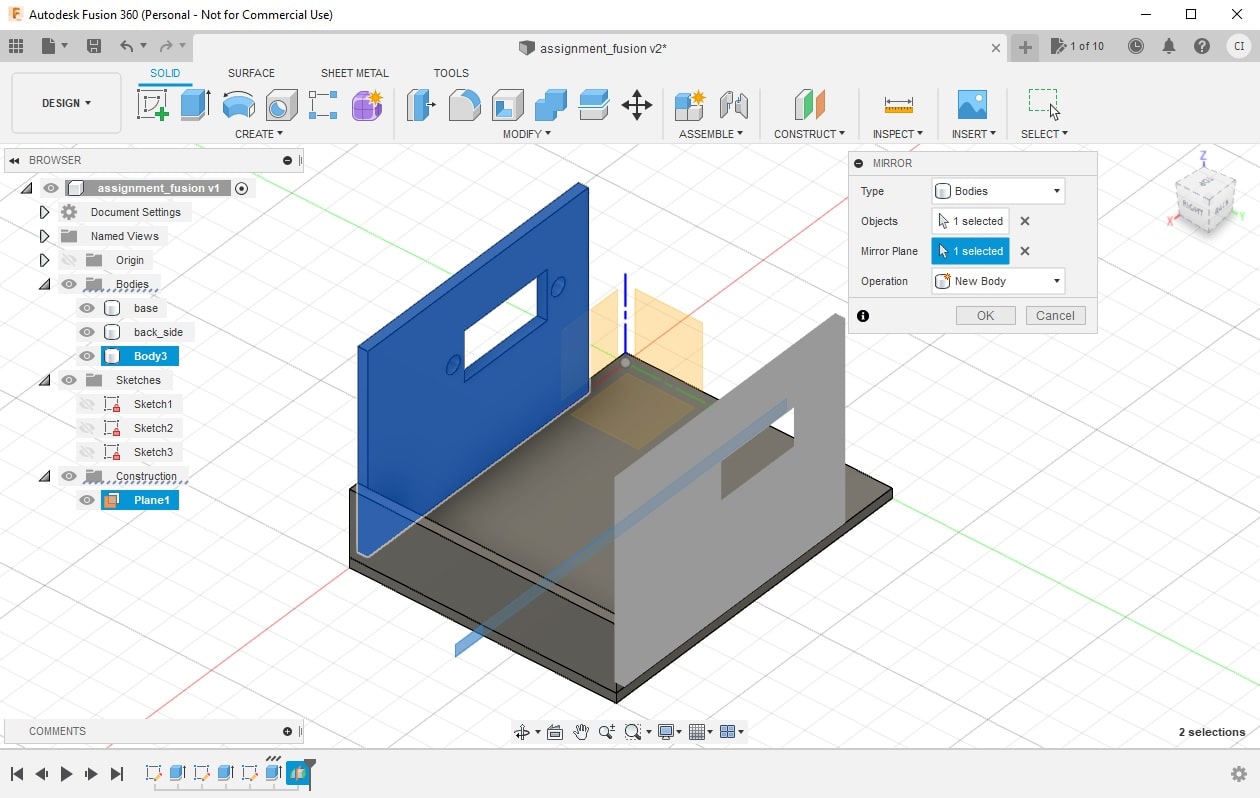
Create a mirror of the left side parte created in the step 8 using the menu CREATE > Mirror. In the dialog of the Mirror menu, select the object you want to mirror and the mirror plane. Select the middle plane create in the step 9. The operation is New Body as I want independent parts of the object.
-
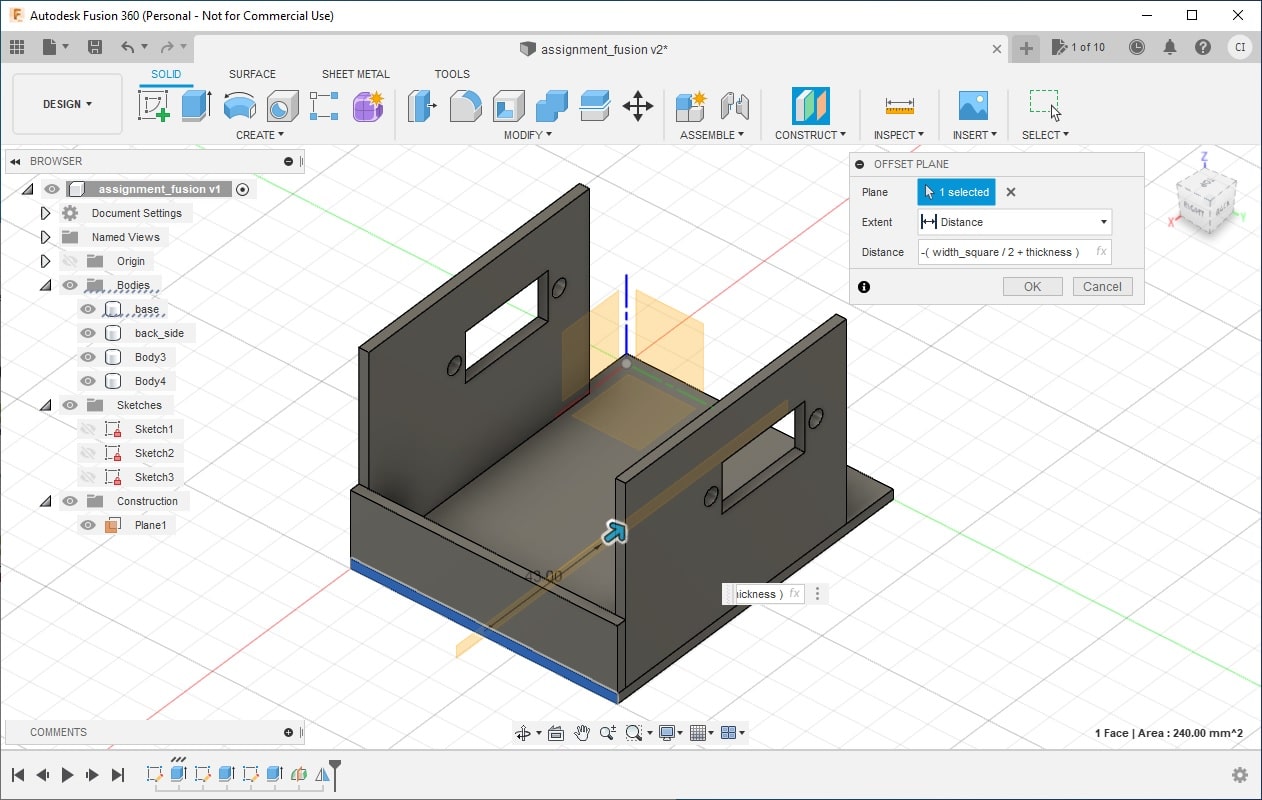
Add a offset plane to duplicate the back side part using the menu CONSTRUCT > Offset Plane. Select the back side part as the reference plane. the distance should be adjusted using the equation: -(width_square/2 + thickness). This plane should be located in the middle of the left and right side parts of the object (width_square/2). There is the offset of the thickness of the back side part (thickness). the minus (-) is to positioning the plane in the right side of the object (between the left and right side parts).
-
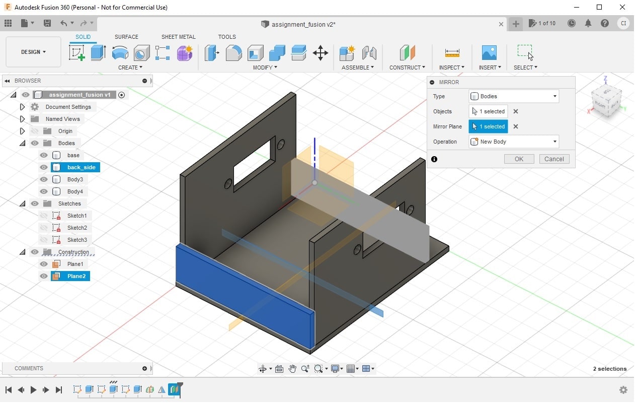
Create a mirror of the back side part using the menu Mirror. In the dialog open, select the object to mirror (back_side) and the reference plane to mirror (plance added in step 11). Choose operation New Body.
-
You can rename the parts to make easy identifying them later. This is the final result for the beginning of the design of the robotic arm.
Download the F3D file resulted from this assignment here.
Onshape
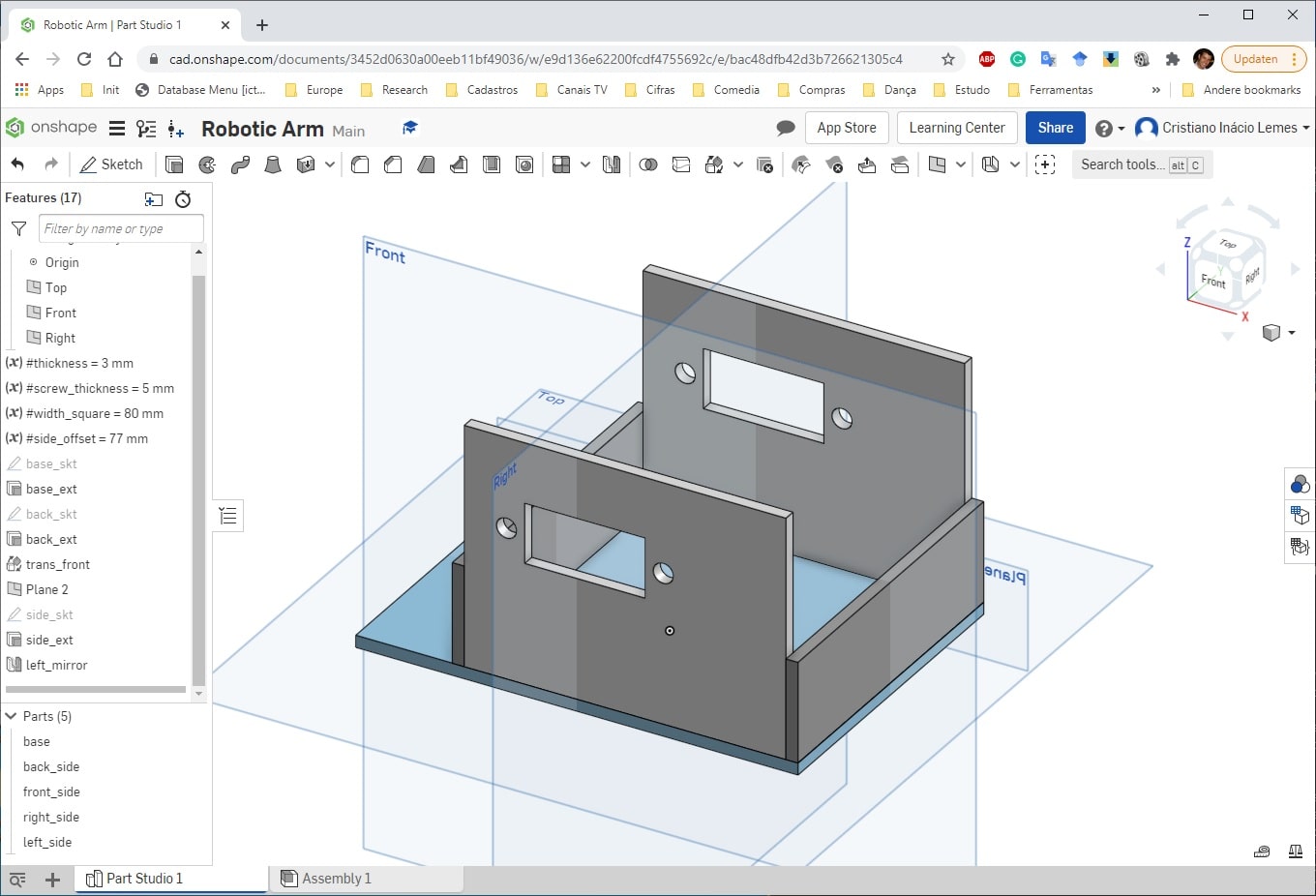
A similar steps were taken using the Onshape cloud version. The components added using Onshape are organized in the order they are added. You can change the order of the object, but there are some constraints that you need to follow. An extrude must to be right after its sketch, otherwise the object will not be created. It was added only the necessary parameters as described in the step 1 before. Steps 3 and 4 were used similarly using the equivalent functions in Onshape, (3) menu Sketch and plane Top and (4) menu Extrude. From step 5 to 8, the operations were very similar. The base part was aligned in the center of the space, which make not necessary the step 9 (to create a middle plane). In the step 10, the XZ plane was used to create the mirror of the left side part. Steps 11 and 12 were different, the back side part were duplicated using the menu right click in the back side part > Copy…. The window open allow to translate the new part. It was used a equation -(#width_square+#thickness), in the axis X to translate the part in the front side of the object. which allow changes in the back side being applied in the front side, it was make a copy of the back side part.
Download the STEP file resulted from this assignment here.
Inkscape
Inkscape is a powerful tool to design vector images with more quality in the final image. It also allows to edit all aspect of your image in a more easy way. However, the tool does not offer a parameter functionality to enable resize entire draw more easily.s The trick used to enable this functionality is using clone tileds from the shapes or group of shapes required. The tutorial explaining this trick can be found here. For this assignment, it was designed a different part of the robotic arm. It was drawn the vertical parts that will be responsible for moving the arm up and down, front and back. It was done the following steps to design this part of the arm. Unfortunately, dua to the lack of time, it was not possible to add an image for all steps taken here.
-
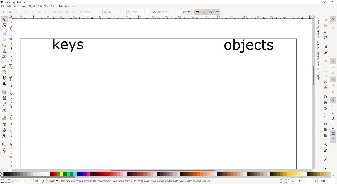
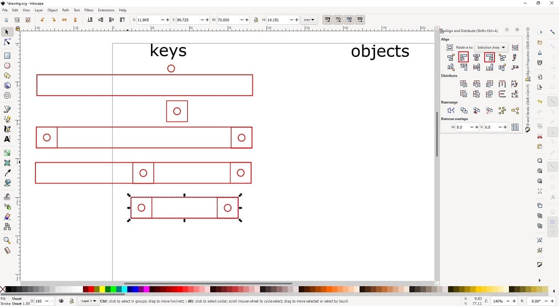
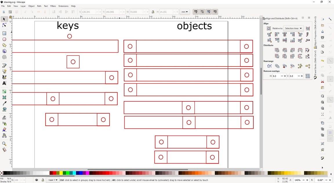
I split the drawing into two sides: keys and objects. The key side I will place the objects that will be used to clone it and create the drawing pieces. The objects are the piece drawn that can be used further to create the prototype of the project.
-
It was drawn the circle in the key side, where the screws will pass to fix the parts of the arm.

-
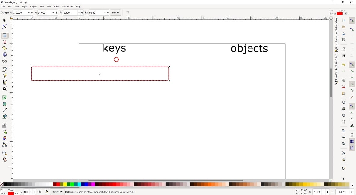
A big rectangule were drawn in the key side with the dimension of 14mm X 140mm, that will represent the horizontal bars of the arm.
-
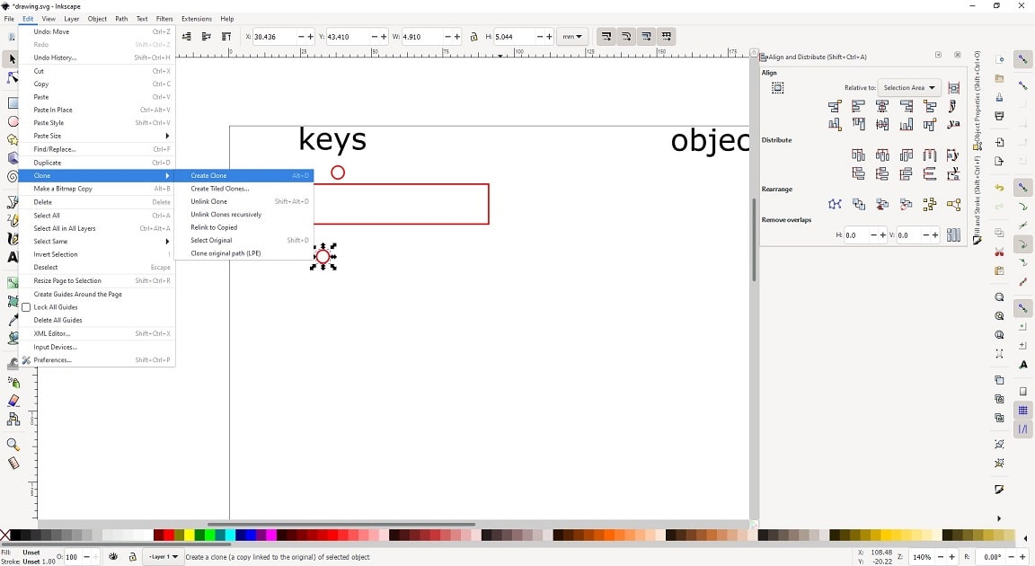
Create a clone of the circle drawn in step 2. The circle need to be a clone (menu Edit > Clone > Create clone (ALT+D)) from step 2. Because changing the property of the circle in step 2 should change all its cloned copies.
-
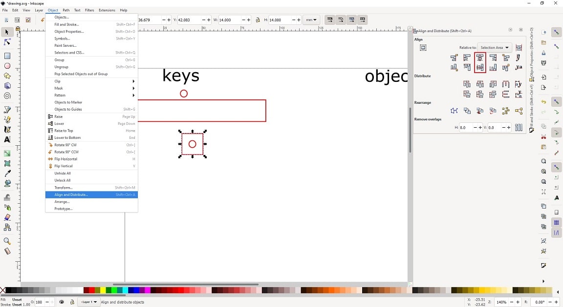
It was draw a square (14mm) with the circle from step 4 inside in the key side. The circle was positioned in the center of the square. To place the circle in the middle, select the square and the circle (holding the keyboard SHIFT to select both at the same time), and uses the options Center on vertical axis and Center on horizontal axis (menu: Object > Align and Distribute…). It is important that the square is selected first, then when using the options the circle will move to the center. If you invert the selection, the square is move to place the circle in the center. Keeping both objects selected I grouped them together, using the shortcut CTRL + G.
-
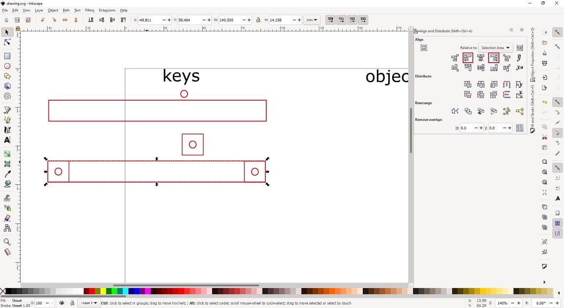
It was create one clone from the rectangle (step 3) and two clones of the square/circle (step 5) in the key side. The square/circle was positioned in the edges of the rectangule. This way the circles are positioned with the same distance from the edges. To place the square/circle in the edges uses the option align right side and align left side (menu: Object > Align and Distribute…) by selecting the rectangle first then the square (one for each side of the rectangle). In the end I group all objects together using the shortcut CTRL + G.
-
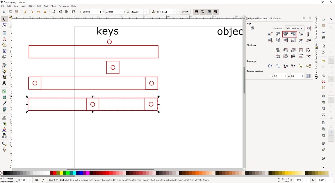
It was create another clone from the rectangle (step 3) and two clones from the square/circle (step 5) in the key side. One square/circle were placed in one edge of the rectangle (using option align right side). The other, were placed in the middle (using the option Center on vertical axis. This will enable the arm go up and down but also in front and back.
-
It was created a small rectangle (width: 70mm, same height: 14mm) and two clones from the square/circle (step 5) in the key side. The square/circles were placed in the edges of this rectangle (options align right side and align left side). This part will be used to attach the servo on it, then the servo can move the arm.
-
It was create four (4) parts from step 6, two (2) from step 7, and two (2) from step 8 in the object side.
-
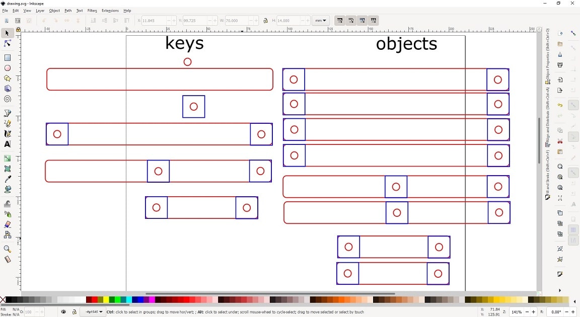
By changing one of the original objects, the clones will be changed as well. This is an important technique that allow you to change dimensions in your drawing without the need of changing each singular object. This is a technique that simulates parameters in Inkscape.
Download the SVG file resulted from this assignment here.