6. 3D Scanning and printing
Assignment
- Group assignment
- test the design rules for your 3D printer(s)
-
Individual assignment
- design and 3D print an object (small, few cm3, limited by printer time) that could not be made subtractively
-
3D scan an object (and optionally print it)
-
All the files done in this week assignment can be find in the repository
Group assignment
3D printing test
Calibration parts
In this activity, parts were selected to calibrate the Sindoh 2x printer, the manufacturer has its own slicing software and settings indicated for this printer model available in Sindoh.
3D printer
The printer used in this project was the Sindoh 2X, a 3d printer that has two nozzles and that can print using two different filaments in the same process. The Sindoh 2X printer has a magnetic base that allows easy removal of the heating bed with a maximum printing area of 228 x 200 x 300 mm, in addition to being able to use PLA, ABS, flexible and PVA in the prints, more information is available in Sindoh 2X.
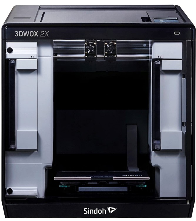
Image1 - Sindoh 2X
Slicing software
The 3DWOX software is the slicer provided by the developer of Sindoh 2X and was used in this activity. First, the software was adjusted for the Sindoh 2X model, which is the printer model used.
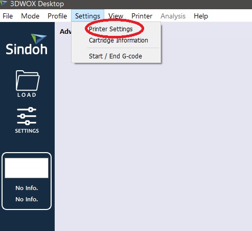
Image2 - Printer Settings
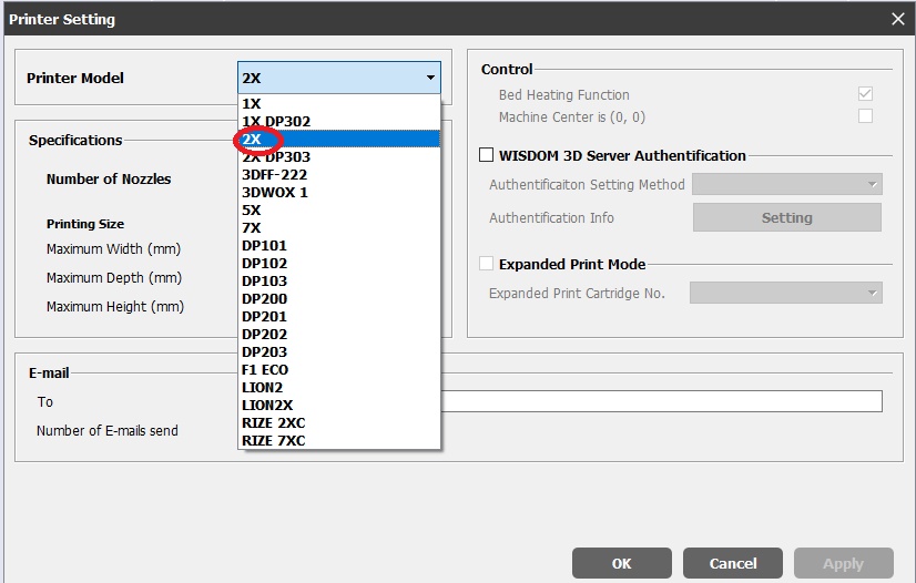
Image3 - Printer Model
With the printer model selected, it was necessary to modify the software for the advanced mode, in this mode it is possible to make further changes in the printing parameters.
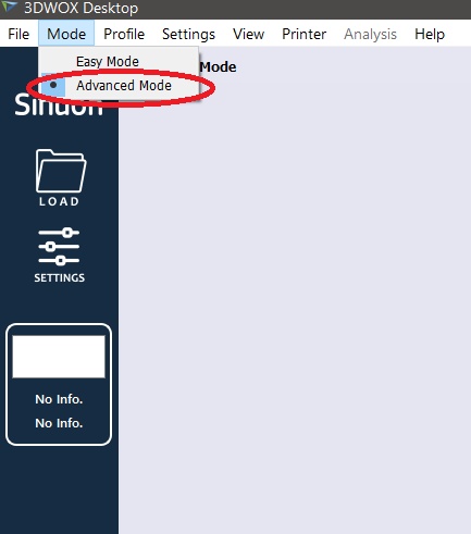
Image4 - Advanced Mode
In settings it is possible to access the printing parameters and modify them.
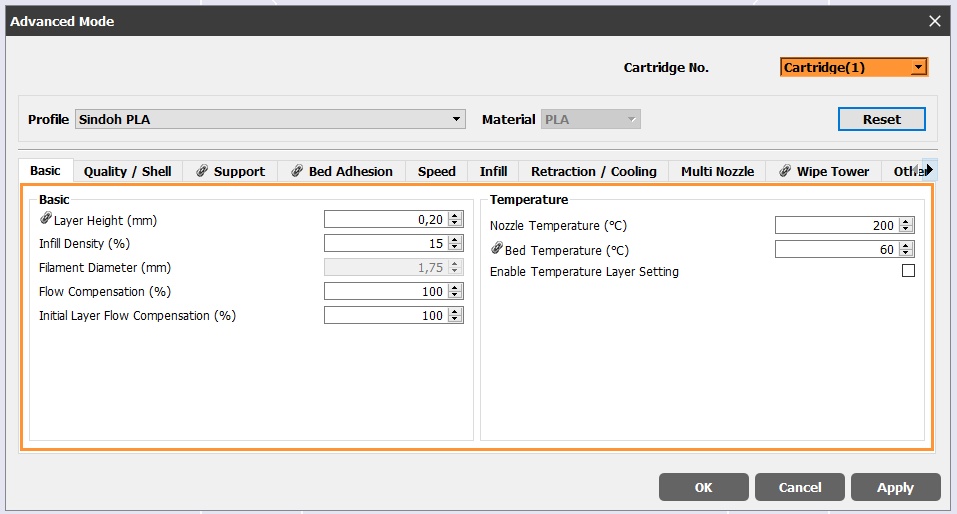
Image5 - Advanced parameters
With the adjustments made, printing tests started.
Test 1
In the first test, a part was used that allowed to test various printing parameters, the file is available in the thingiverse.
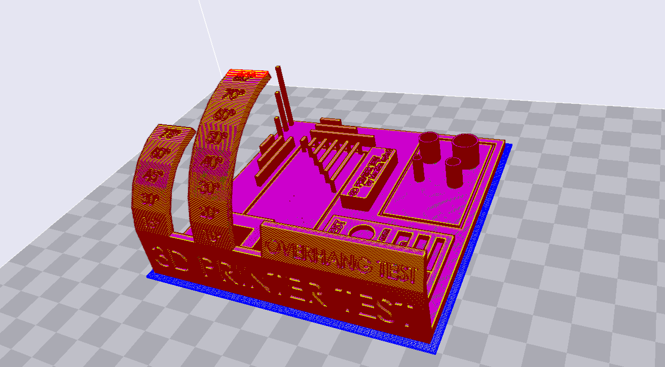
Image6 - Test part
The tested parameters and their measurements are indicated below:
- Bridging test de 2mm, 5mm, 10mm, 15mm, 20mm, 25mm (maximum bridge that can be made without support)
- Diameter test de 4mm, 6mm, 8mm, 10mm (1.0mm wall)
- Hole test 4mm, 6mm, 8mm
- Support test
- Overhang test (Print angulation without support).
The slicing parameters used:
- Layer height: 0.20 mm
- Wall line count: 2
- Top layers: 2
- Bottom layers: 2
- Infill: 30%
- Speed: 60 mm/s
- Nozzle temp: 210 °C
- Bed temp: 60 °C
- Material: PLA
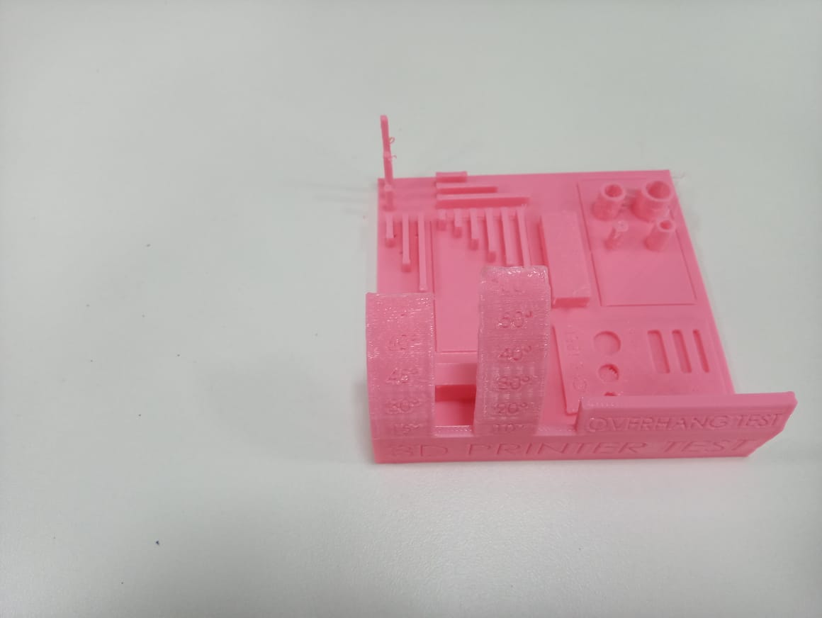
Image7 - Part printed1
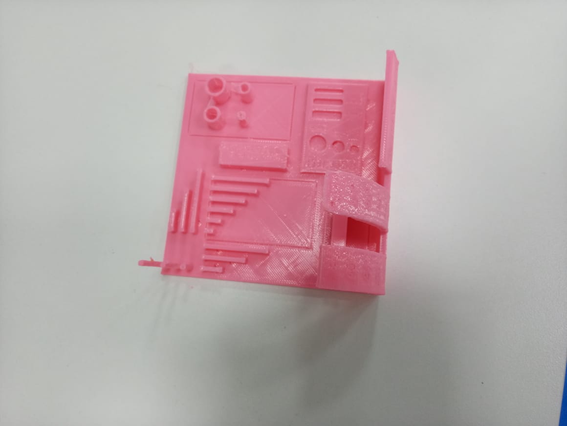
Image8 - Part printed2
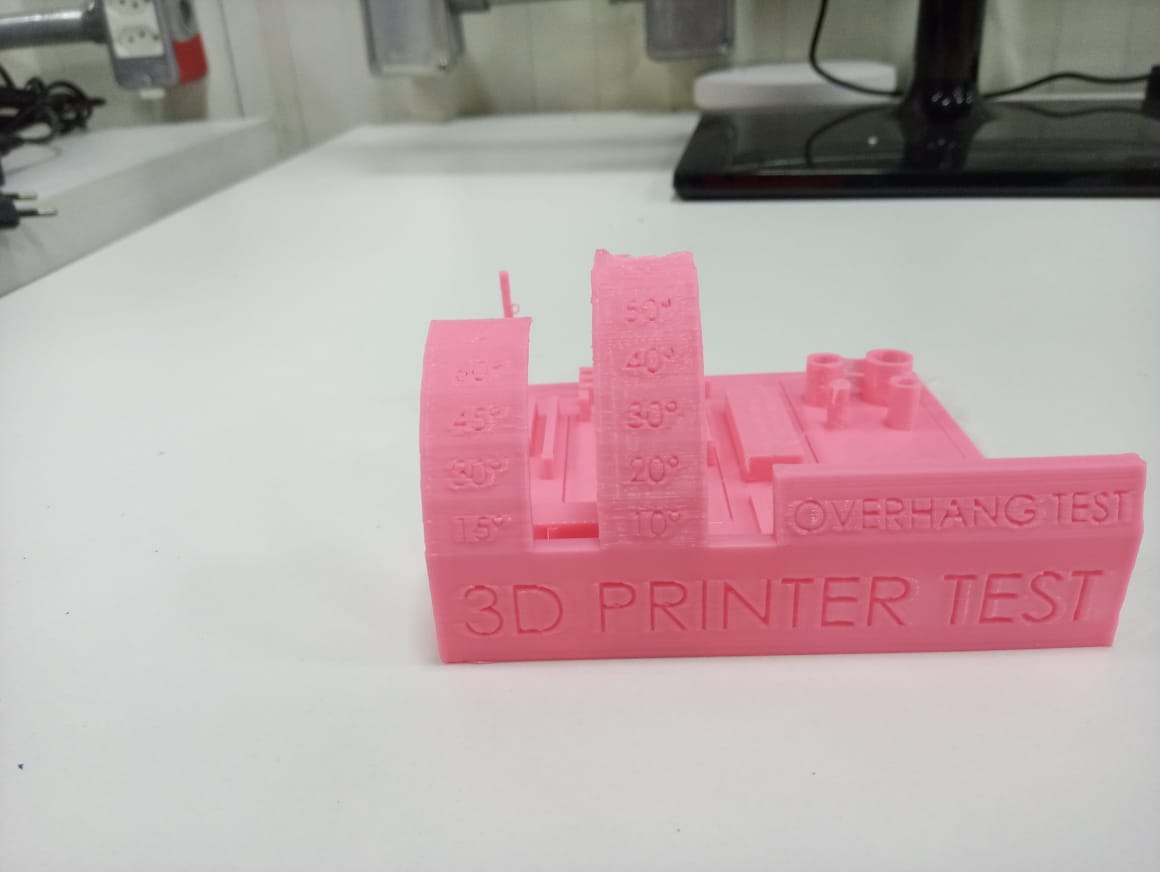
Image9 - Part printed3
The printed part showed lines between the diameter tests, a retraction problem and in the overhang test it achieved a maximum angulation of 45° without suffering deformation, the other parameters of the part did not present problems. The piece had a printing time of 5h 14min and used 44.9 grams of PLA.
Test 2
The retraction tower test aims to find the best retraction parameter for the printer, the retraction is when there is a pull on the solid part of the filament that generates a negative pressure on the liquid part of the filament that is in the nozzle and helps to prevent the sliding of the filament, thereby preventing lines and bubbles in the 3D part. A part was then chosen to perform this test, the model file used for the test is available on the thingiverse.
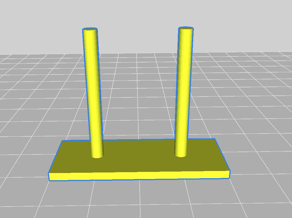
Image10 - Retraction test part
The test model was printed using the slicer parameters presented above but had its retraction values modified. Retraction parameters used in the first part:
- Speed: 30 mm/s.
- Length: 6,0 mm.
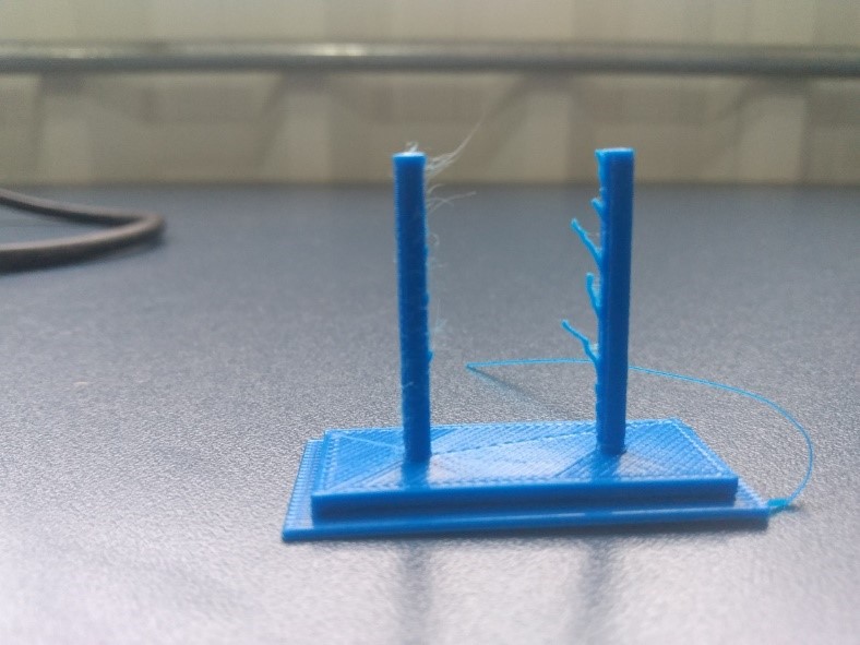
Image11 - Falied test part printed
The first part had some lines and did not pass the retraction test, so the retraction values were changed, and other tests were performed. Retraction parameters used in the final part:
- Speed: 33 mm/s.
- Length: 7,0 mm.
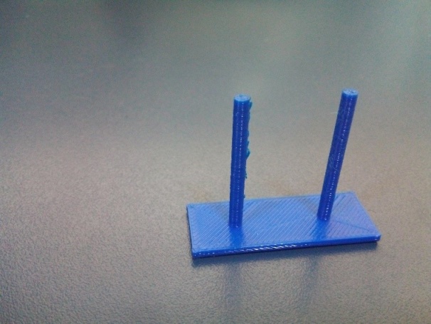
Image12 - Sucess test part printed
With the retraction parameters previously presented, the part presented almost no retraction problem, so these are the ideal values for retraction of this printer.
Calibration Cube
The XYZ calibration cube test aims to verify that the axes of the 3D printer are correctly calibrated, the part is a 20 mm³ cube and through a calculation using the value of the original dimension and of the impression is possible to reach a new value of steps per millimeter, which is a parameter of the 3D printer and influences the dimensions of each axis of printing. The model file used for the test is available on thingiverse.
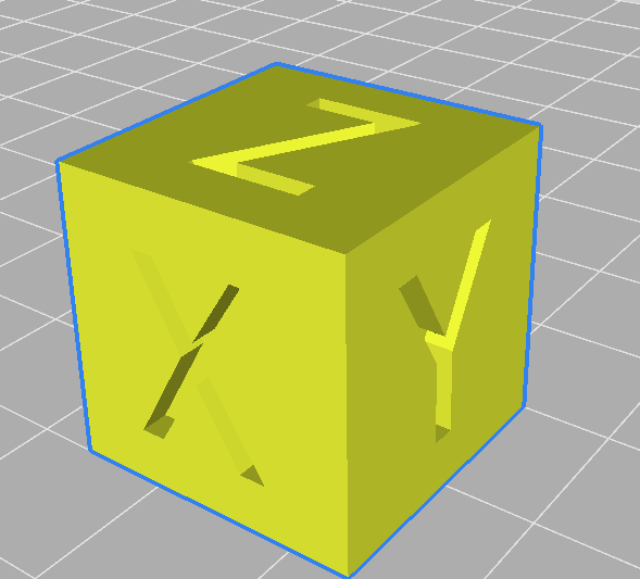
Image13 - Calibration cube
Flow test cube
The flow test cube is a piece that is used to test the nozzle feed flow, with which it is possible to observe the variation in the thickness of the layers of the walls. A test was performed using a wall thickness of 0.80 mm and a flow of 98%, for these parameters the impressions presented the correct value for wall thickness, the model file used for the test is available in the thingiverse.
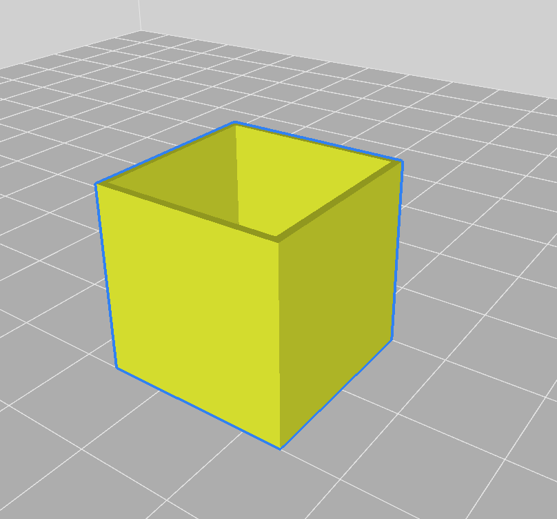
Image14 - Flow test cube
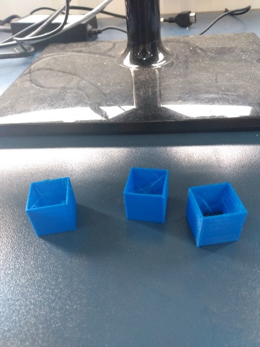
Image14.1 - Printed flow test cube
Individual assignment
3D Modeling
3D Model
This activity aimed to create a 3d model and print it, so first the Tinkencad software was used to develop the 3d model, this software is free and easy to use. I wanted to create a simple piece that was easy to model, so I made a model of a turtle. First, a half sphere was made, which would be the shell.
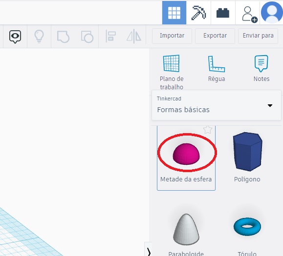
Image15 - Tinkercad Half Sphere
A sphere was created as the animal’s head, positioned next to the half sphere and its dimensions were modified.
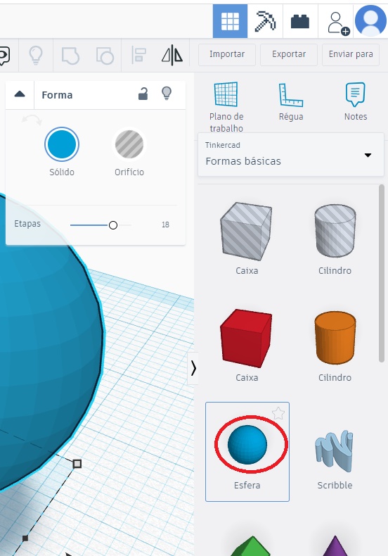
Image16 - Creating a sphere for the head
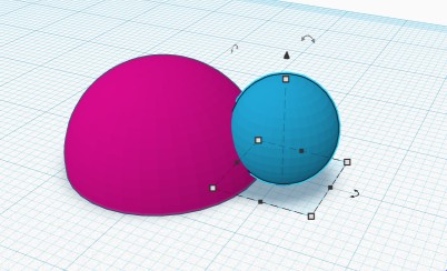
Image17 - Head and body
Round roofs were used as the turtle’s fins.
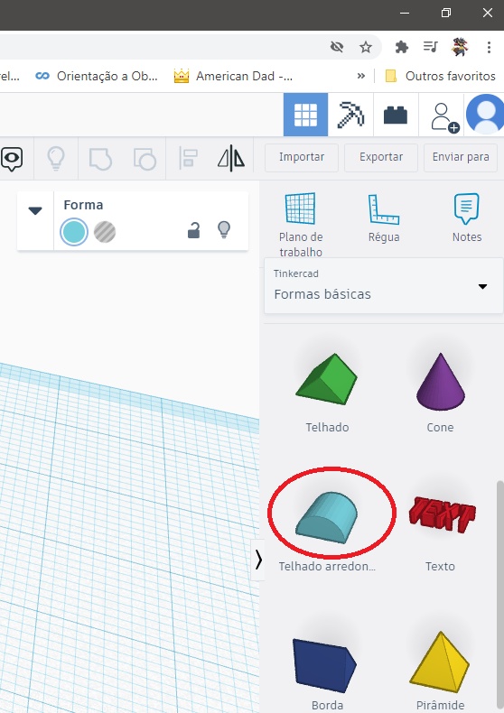
Image18 - Creating a half roof for the fin
The dimensions of the round roof were modified and positioned close to the half sphere.
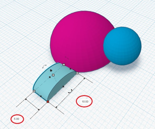
Image19 - Fin dimensions
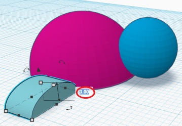
Image20 - Fin dimensions 2
With the modified round roofs, the copy and paste function was then used to generate the other fins.
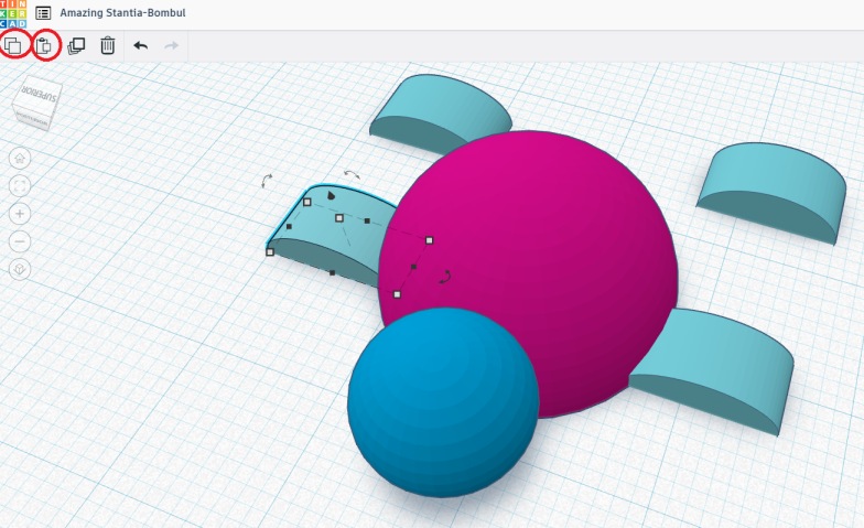
Image21 - Copying the fins
By clicking on the roof, it is possible to modify its angle.
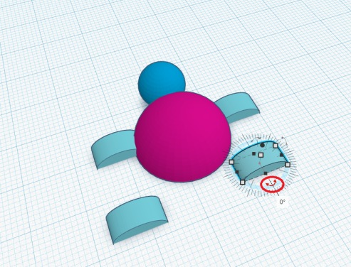
Image22 - Rotating the fin
The roofs were positioned at a 45 ° angle and close to the half sphere, the piece is ready and can be exported.
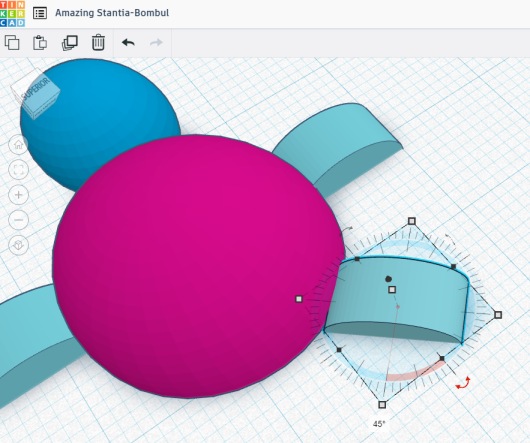
Image23 - Rotating the fin 2
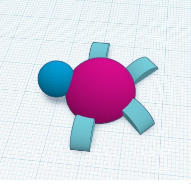
Image24 - Turtle complete
After finishing the 3d model, the file was exported. Tinkencad allows the file to be downloaded in 3 types for 3D printing, OBJ, STL and GLTF, the exported file was the STL type.
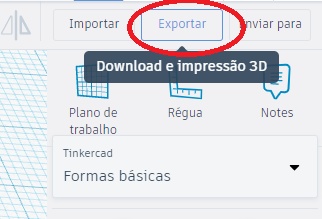
Image25 - Export
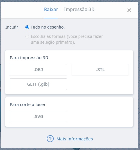
Image26 - Download STL file
Slicing
With the STL file of the part, slicing was started using the Sindoh software for the 2X model. The STL file of the 3d model was imported into the slicer and adjustments were made to the printing parameters to improve the quality of the piece.
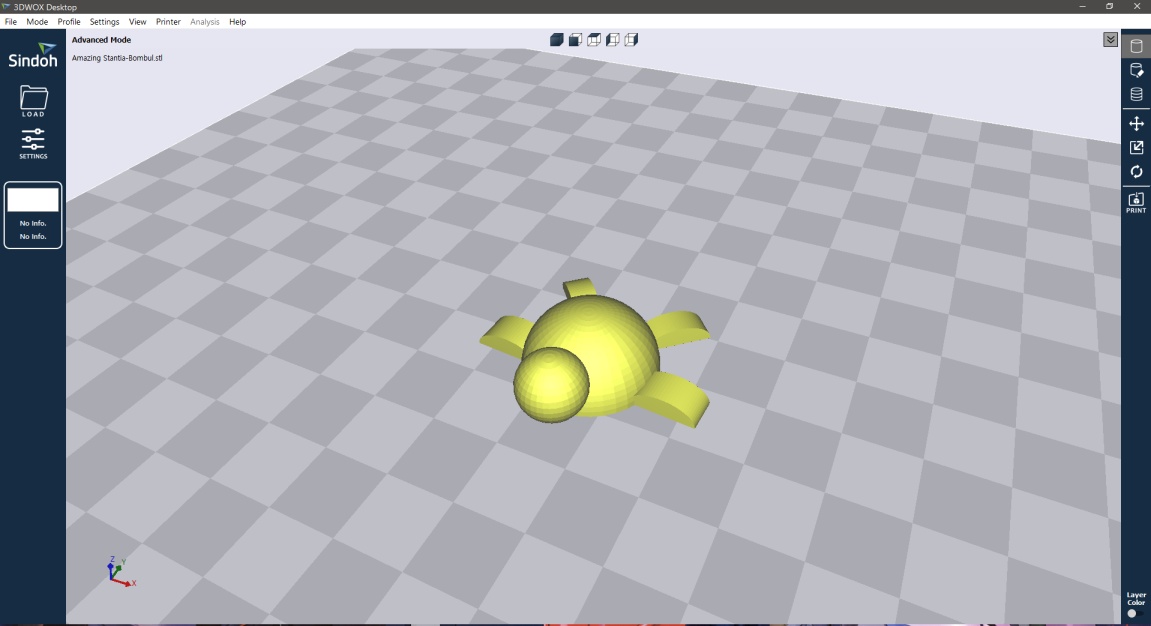
Image27 - File on Sindoh Software
A 0.05 mm high layer was used to make the part smoother. The nozzle temperature was 210°C for the PLA used with a printing speed of 60 mm/s. These temperature and speed values were tested and have good print quality. As the piece does not suffer many contractions and is basically a decorative piece, a 10% fill was then used to shorten the printing time.
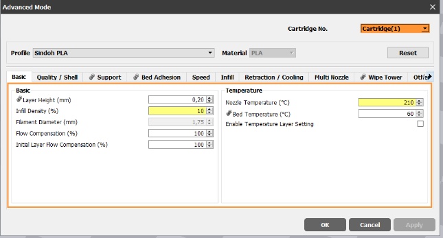
Image28 - Advance mode parameters
Finalizing the slicing
With the addition of the parameters to the slicer, the layer view was started to calculate the printing time and the amount of material used.
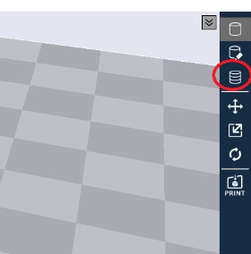
Image29 - Layer view
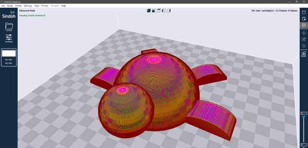
Image29.1 - Layer view
The piece has a printing time of 5h 01min and uses 47.0g of PLA, with that the piece was exported to a usb stick and uploaded to the 3d printer, with this the printing process was started and the final piece was obtained.

Image29.2 - Printed turtle
Printing test
To prove that the modeled part could not be made by subtraction, a second 3d modeling was performed using the Inventor, a 3d modeling software. The steps for the modeling were:
- Draw an S using lines like the one in the figure below.
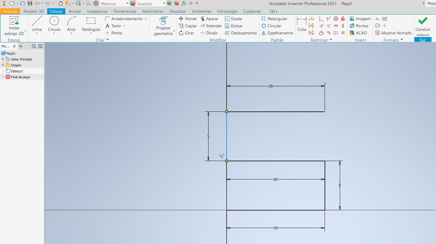
Image30 - Draw a S
- Round the corners 90 ° with the rounding, a rounding of 2mm was used.
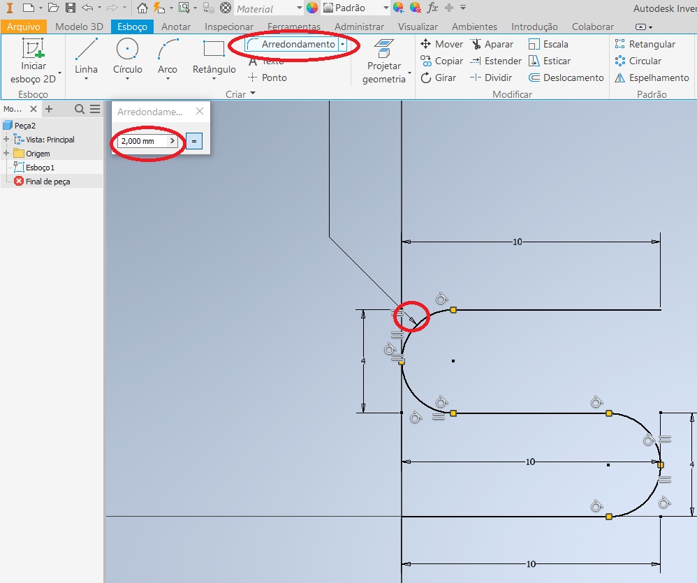
Image31 - Round the corners
-
After sketching the S, it is necessary to modify the section of the part view to perform the next steps.
-
It is possible to modify using the cube on the side, as it presents the views of the part.
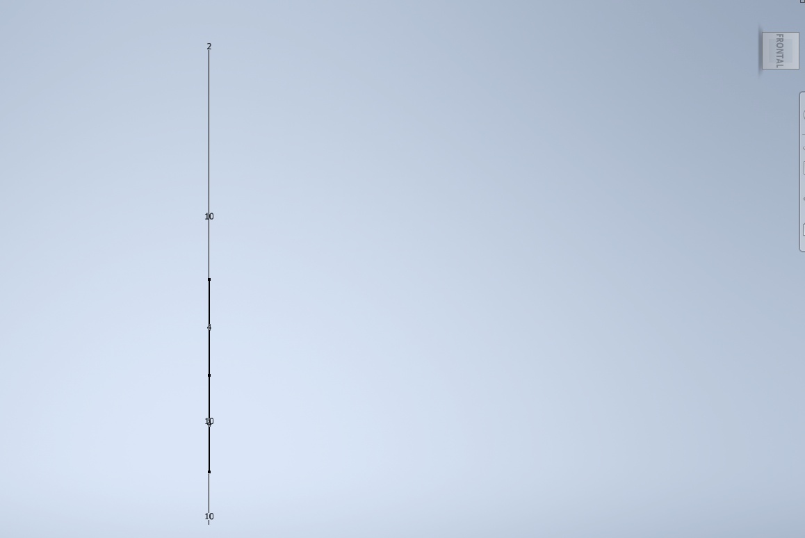
Image32 - Rotating the view
- In this new view, it is necessary to start a sketch and then draw a circumference on one of the ends of the S.
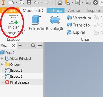
Image33 - Sketching a circumference
- To create the solid model of the S it is necessary to scan.
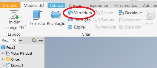
Image34 - Scanning to create a solid model
- And then click on the circle, select the rest of the S outline, and click ok.
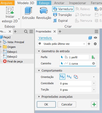
Image35 - Selecting the route to be scanned
- With the 3d model of the S ready, I added a hollow part to the interior of the part.
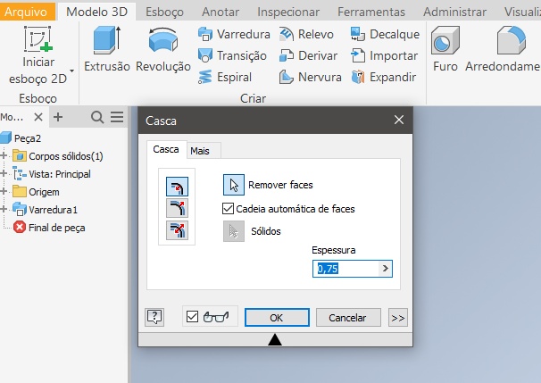
Image36 - Adding a hollow part
- To create the hollow part, it is necessary to click on the shell, select the two circular faces of the S, and add the value of the shell thickness.
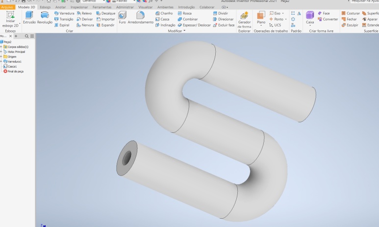
Image37 - Adding thickness to the hollow part
- The part is finished and can be exported for printing.
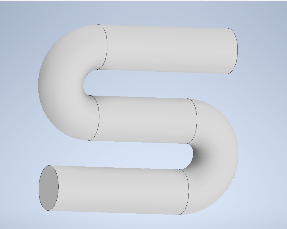
Image38 - Finished model
- To save the file in STL, select save as and then save copy as.
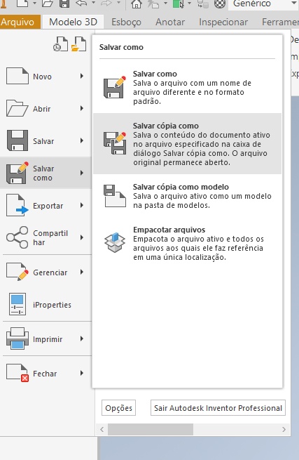
Image39 - Saving
- I selected the file type as STL and saved it.
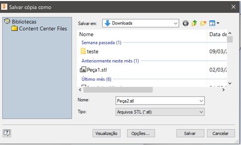
Image40 - Saving as STL file
- With the piece in STL we can open the piece in the slicer and generate the print file.
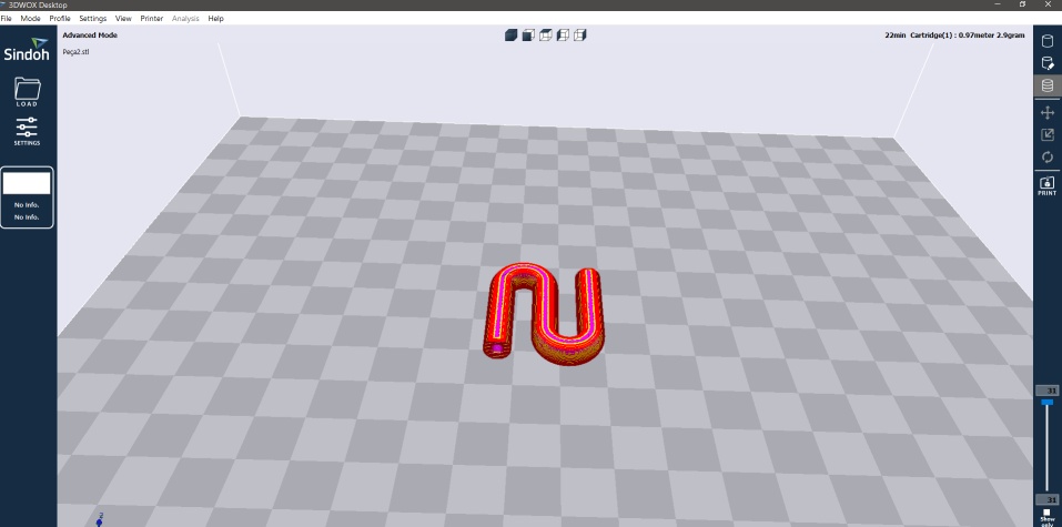
Image41 - Layer view on Sindoh software
- Finally, the impression shown below was made.
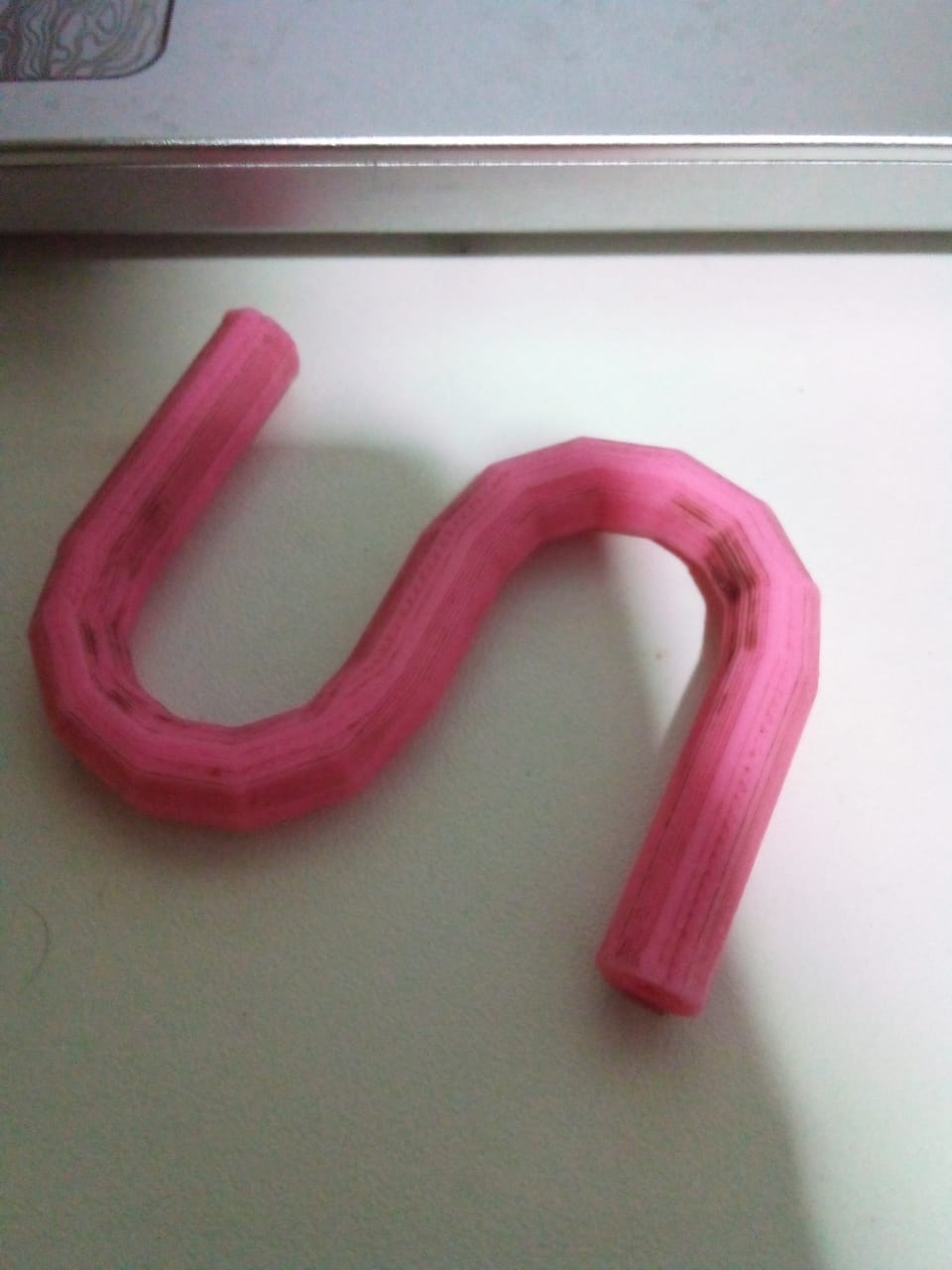
Image42 - Printed part
Two-Filament Printing
The part below was used to perform the test of printing with two filaments. To perform the printing using two filaments, the Sindoh 2X 3d printer was used and it was necessary to:
- Click in layer color.
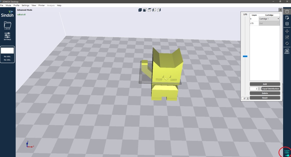
Image43 - Change the color of the layers
- Select how many layer divisions you want and click on Equal Distribution.
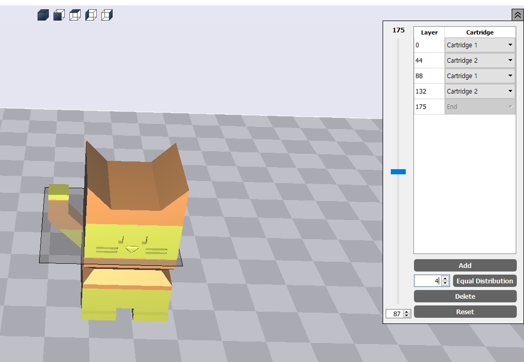
Image44 - Selecting the number of layers
- With the print settings made earlier, we can print the part, but due to the nozzle alignment problem of the Sindoh 2X printer on the lab, it was not possible to perform this printing, as the nozzles did not align on the Y axis of the 3d printer.
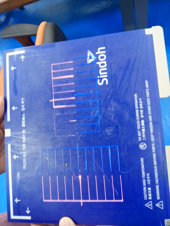
Image45 - Alignment error
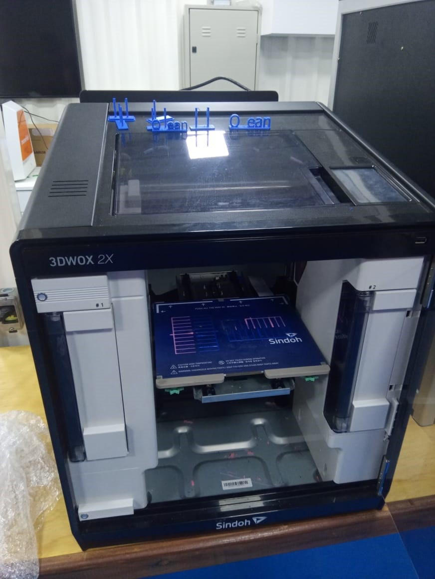
Image45.1 - Alignment error 2
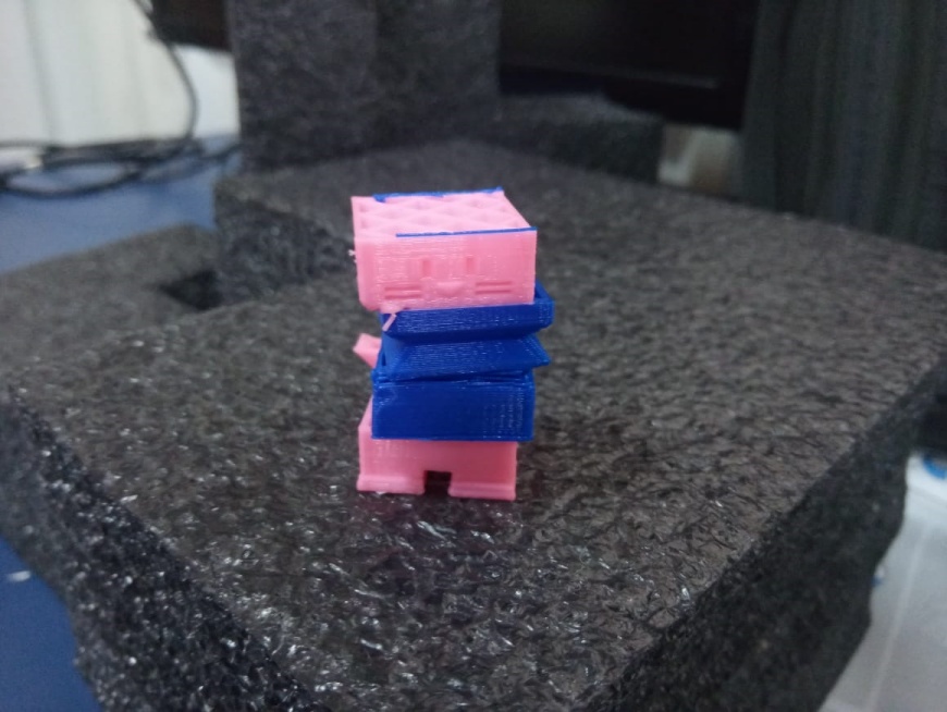
Image45.2 - Alignment error 3
3D Scanning
Photos
First, an object was chosen to be scanned and then a series of photos of the object were taken, the photos were taken around the object and in other angles so that the object had its details well captured.
The first tests showed many flaws, as they reflect a lot of light, they were small and the environment interfered a lot in the result, so after many tests this plush walrus was selected as the test object. The photos have dimensions of 1212x2560 and 72 dpi of horizontal and vertical resolution, the photos were taken using a Samsung model A01 cell phone.
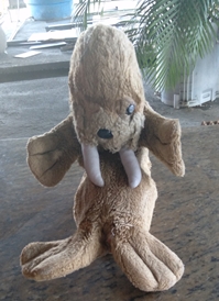
Image46 - Photo of the plush walrus
3D scanning program
Meshroom was the software chosen for 3D scanning, after the studying of various software that could be used, it is easy to use and it is free. The photos taken were added to Meshroom and 3D scanning started.
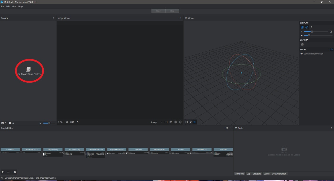
Image47 - Inserting the photos
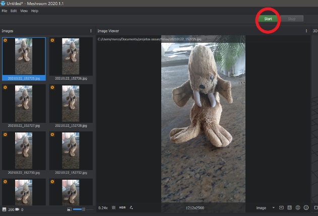
Image48 - Save the file
With the photos added, the saving of the final file starts when clicking on Start, the final file will be saved with its texture components.
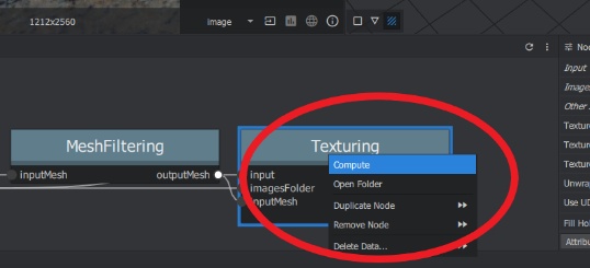
Image49 - Start the scan
Clicking on “Texturing” and then “Computer” starts the 3D part assembly process, because 200 photos were used the assembly process took a long time.
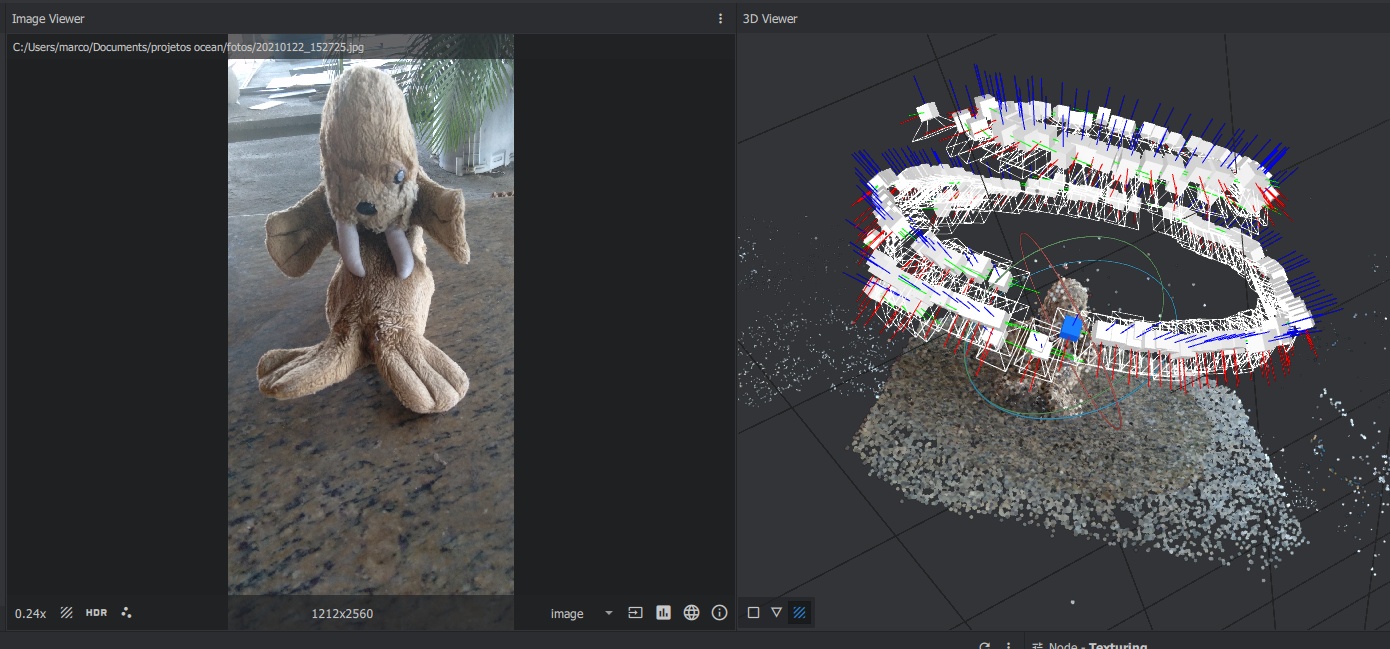
Image50 - Finished 3D model
After finishing the process, it is possible to observe the reference points used by the software for assembling the model (the white blocks) and that a good part of the environment was also scanned next to the object. In the save location of the file, the final model in the OBJ type extension is found.
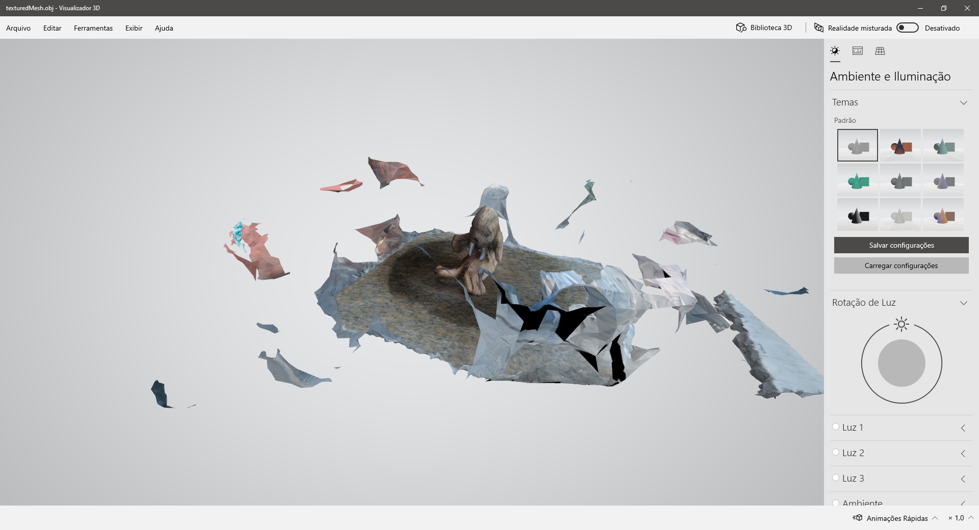
Image51 - File after Meshroom
Cleaning 3D Model Environment
For the realization of 3D printing, it is necessary to remove the environment that will cause problems in printing, for this purpose the free software MeshLab was used.
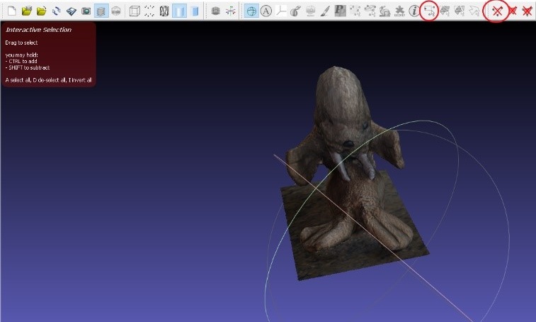
Image52 - Removal from the Environment
Using the two functions marked in red in the image above, it is possible to select and delete objects from the file, so the environment was removed so that the object would look like the one in image that shows the file after Meshroom. With the environment removed, the file that was saved was exported in STL.
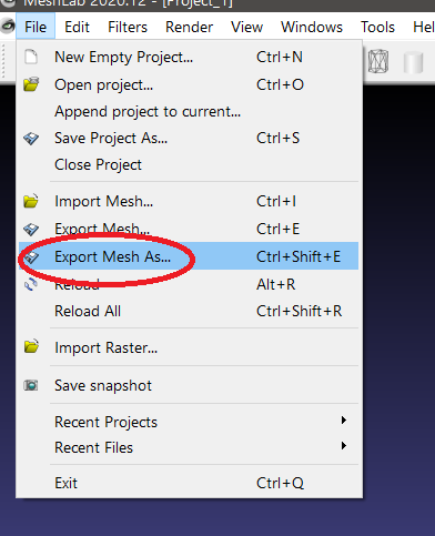
Image53 - Export Mesh as STL file
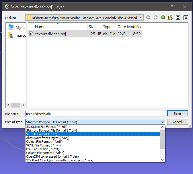
Image53.1 - Export Mesh as STL file 2
A problem presented by the 3D model is that it is open as seen in the image bellow.
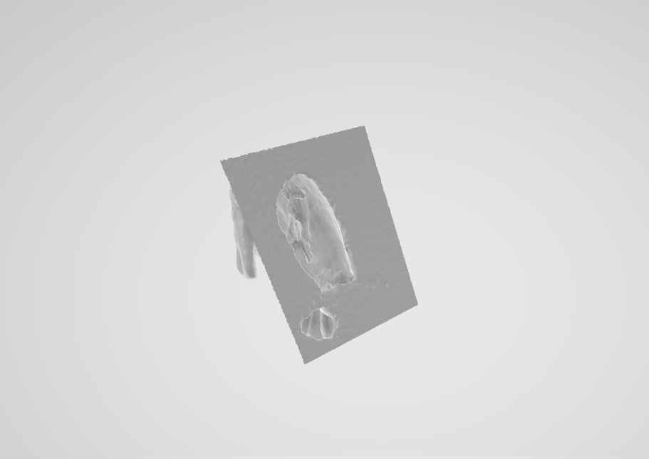
Image54 - Hole in the bottom of the model
Closing the Model
Meshmixer was used to close the part. This software allows modifications to the 3d model and other processes, it is a free software and extremely useful for modifying parts.
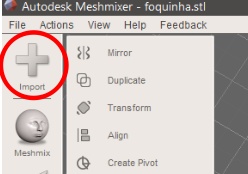
Image55 - Importing the part into Meshmixer
Importing the 3D model into Meshmixer, it was possible to close the part, using the “Make Solid” option located in “Edit”.
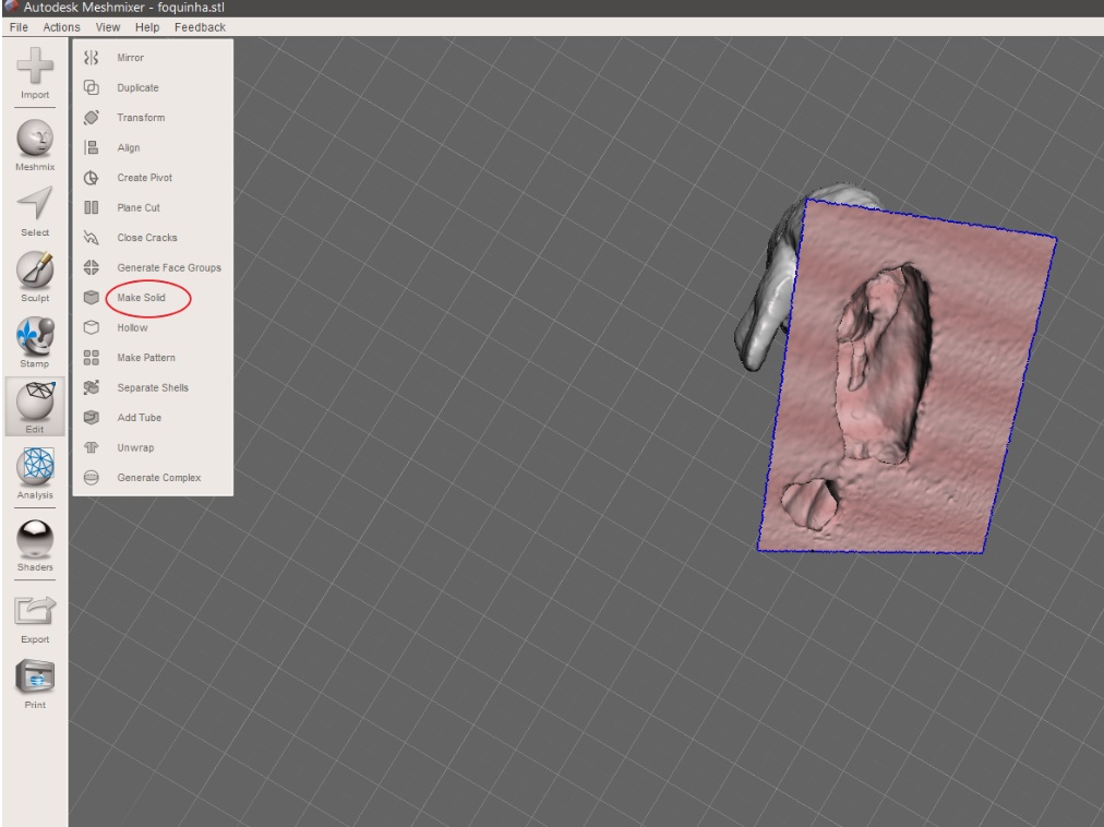
Image55.1 - Making solid
When the piece closes it is possible to see some pieces loose in the air, this is due to the “solid type” be in the fast mode, to avoid this, an update to the “accurate mode” was performed, which presented a better quality and without the defects presented previously.
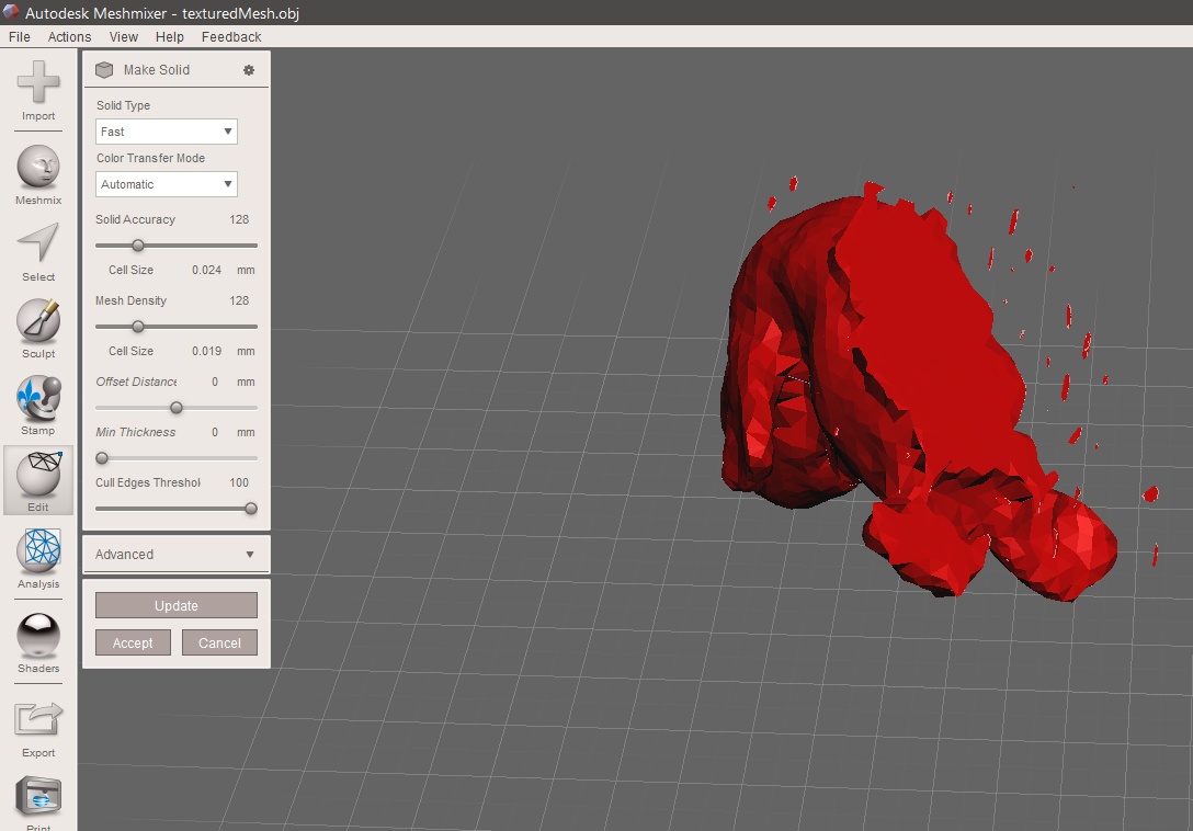
Image55.2 - Solid part
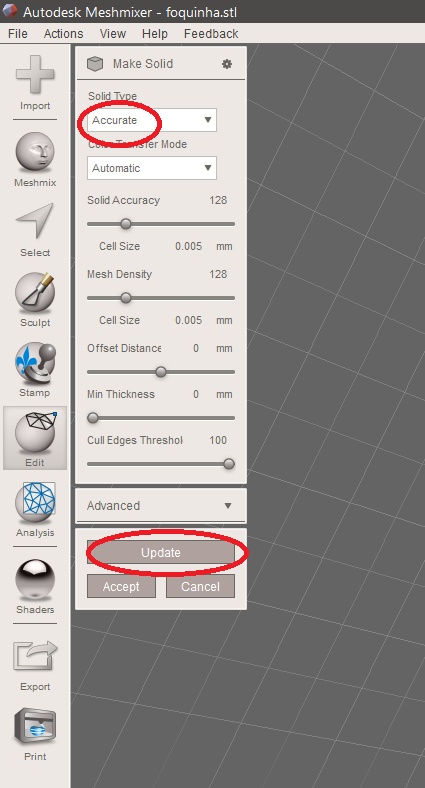
Image56 - Accurate mode
With the solid part it is possible to save the file in STL and we can pass the file to the 3D printer software
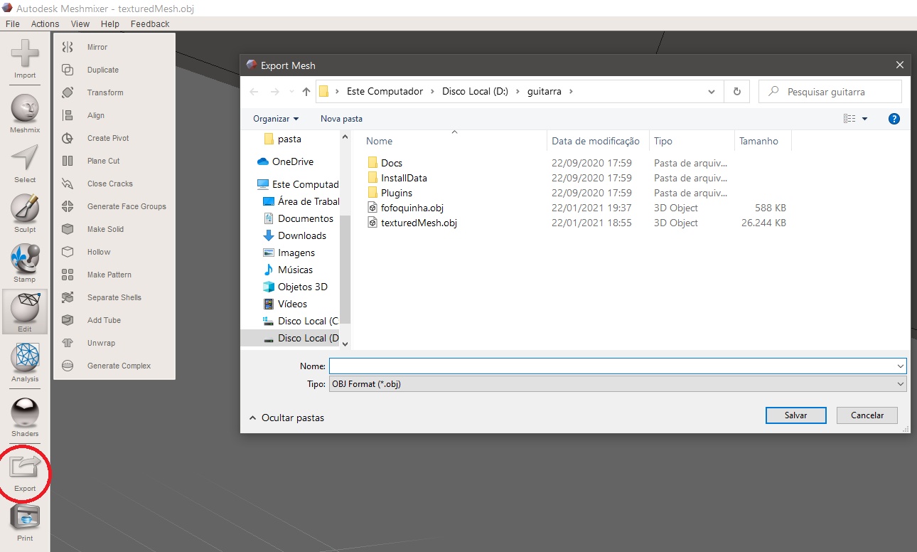
Image57 - Save in STL
Model slicing
When the piece was loaded onto the slicer, it was in a position that would need many supports for its printing, to avoid this, the slicer rotation function was used to rotate the axes of the piece. A flat lay was also used to try to locate and place a flat part of the model in contact with the printing table.
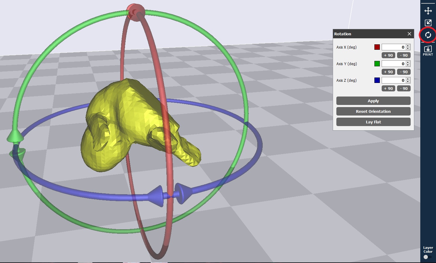
Image58 - Rotating the model
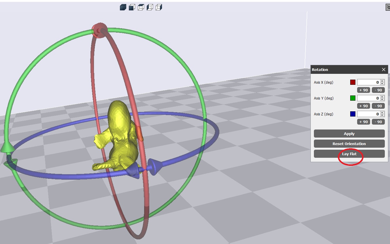
Image59 - Lay flat
After many axis rotations and the use of the flat lay, the side that was filled by Meshmixer was in contact with the printing table and with that the part could be printed more easily. When printing, a 0.05 mm high layer was used to make the piece smoother, the nozzle temperature was 210°C for the PLA used, with a printing speed of 60 mm/s. The part was increased by 50% and a fill of 10% was used to decrease the printing time.
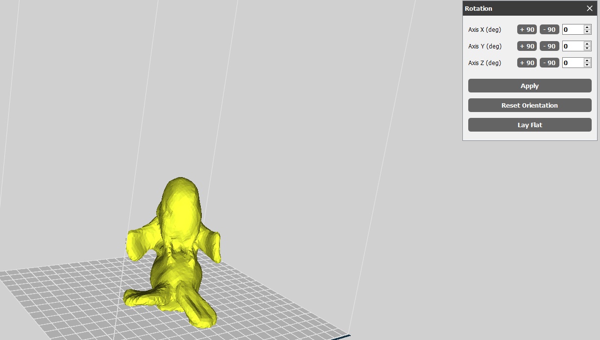
Image60 - Order in the slicer
With the addition of the parameters to the slicer, the layer view was then started, the printing time was 27h 12min and used 80.4g of PLA.
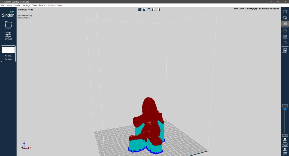
Image61 - Layer view
The part has been reduced to have a shorter printing time and is shown below.
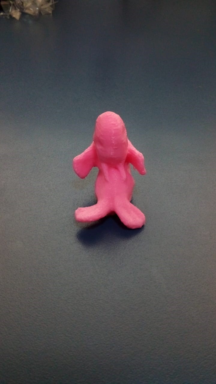
Image62 - Printed part