8. Computer controlled machining
Assignment
- Group assignment
- do your lab’s safety training
- test runout, alignment, speeds, feeds, materials, and toolpaths for your machine
- Individual assignment
- make (design+mill+assemble) something big (~meter-scale)
Individual Assignment
Design
My idea for this week is to create a MDF (Medium-density fiberboard) tic-tac-toe to play with my son. The idea is to create a board where the X or 0 pieces fit like a puzzle.
The Project was also based in a Vectric Ltd youtube video.
Below in we can see the concept idea of the project
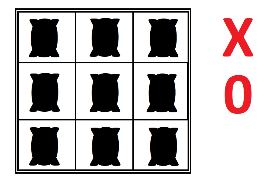
Image1- Tic-tac-toe
Using the concepts applied until this week, I created a vectorized model in VCarve Pro, composed of: - Board. - 0 pieces. - X pieces.
Note: Cut2D Pro was acquired during the purchase of the ShopBot CNC milling machine. This software offers a powerful and intuitive solution for cutting parts with a milling machine. The software can import 2D designs from other software. For more information can be access here.
All sketch lines created in Cut2D are automatically vectors. I will then show you step by step the construction of my tic-tac-toe project in the Cut2D software.
First, I created a new project, then I chose the dimensions of my work area for modeling. I used 190.5mm in the X axis, 190.5mm in the Y axis and 14.5mm in the Z axis. It is worth mentioning that these 0.5 is because of the design of the board to put the 0 and X pieces.
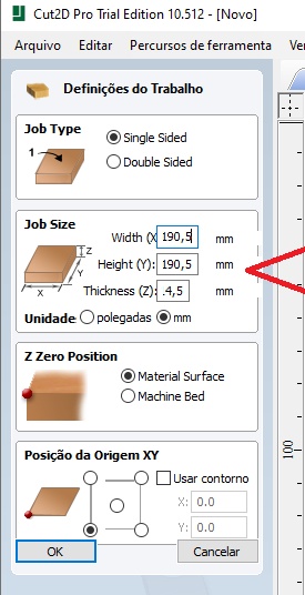
Image2- Job size
After clicking “ok”, a menu with sketch creating options will automatically appear on the right side of the screen. In this menu, I select the “Draw Rectangle” tool and then the parameters that I consider ideal for this geometrical figure, again adding 0.5mm extra of margin for milling.
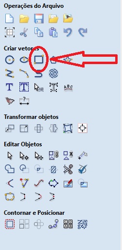
Image3- Draw Rectangle
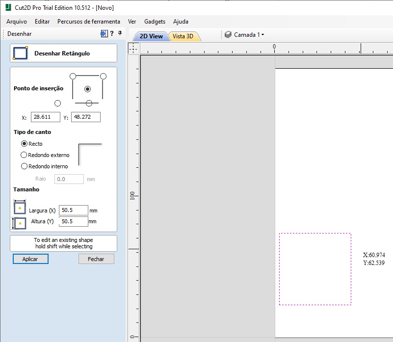
Image4- Draw Rectangle 2
After creating the first square, I select it together with the “Array Copy” tool located at the bottom of the sketch creation tools menu.
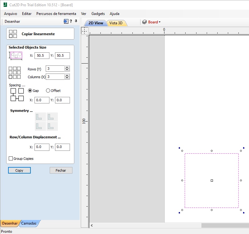
Image5- Array copy
This tool allows me to create sequential copies following linear logic. In this way, I select the number of squares that should appear on the X and Y axis of the sketch and the distance between them and obtain the following figure.
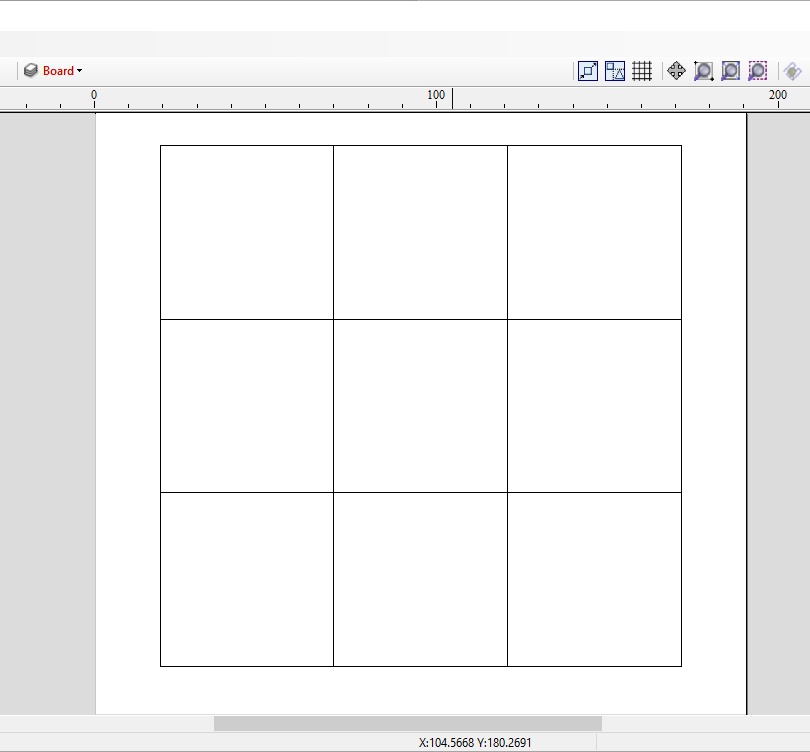
Image6- Array copy result
Selecting the “Draw Rectangle” construction tool again I create a square that surrounds the previous sketch, with 4mm from the edge. So, the dimension of this square will be 158.75x158.75mm, aligning the outline in the middle of the work area.
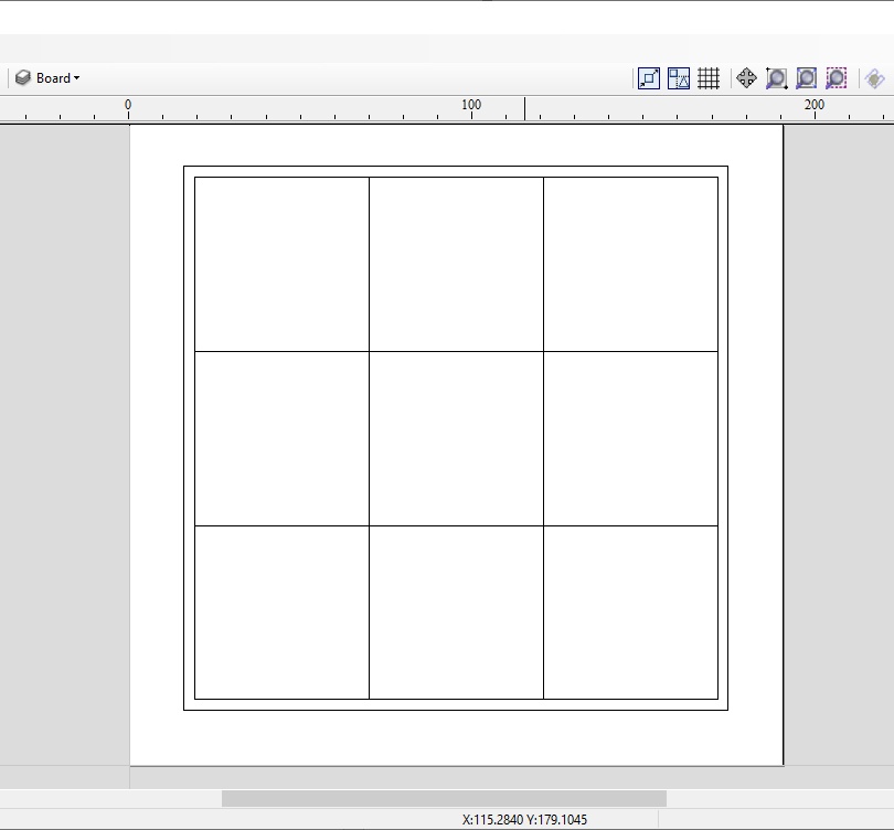
Image7- Draw external rectangle
The next step is the creation of X and 0 pieces, in addition to their overlapping molds. For this, I select the tool “Draw text - within a vector box”.
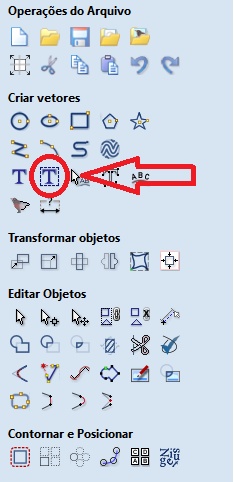
Image8- Draw text - within a vector box
I select any of the internal squares and write X, then another square and I write 0, both in Arial font, bold, without worrying about the font size because once the square is selected, the font size will automatically adjust to the dimensions of the geometric figure.
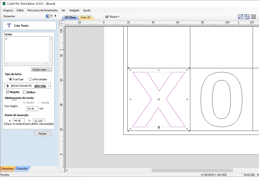
Image9- X and 0
Then I select the tool “Fillet” and smooth the vertices of the X using an arc with 0.2mm radius to facilitate the milling work.
Image10- Fillet
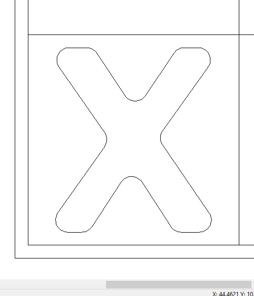
Image11- Rounding the X
Note: In this step I saved a file for X and 0, since they are different pieces and will be milled separately from the board.
That done, I overlay X and 0, select both figures and then select the tool “Weld”.
Image12- Weld
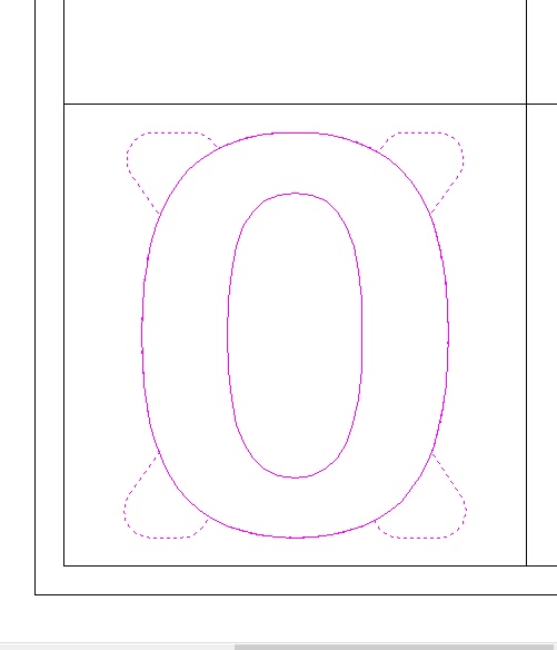
Image13- X and 0 overlay
This way I get the following overlapping of joined vectors.
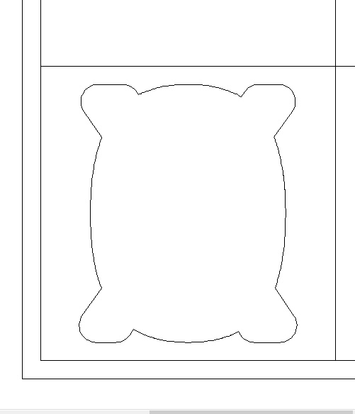
Image14- X and 0 weld result
Now just copy and paste the same overlapping vectors to the other internal squares.
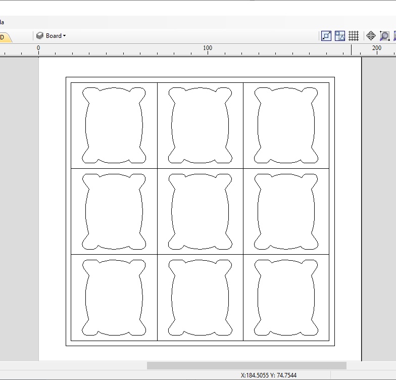
Image15- Copying the result to all squares
The next step is to simulate the milling of this sketch. For this we will subdivide it in 4 sub steps, following the order below as milling order:
-
Profile Border.
-
Profile Lines.
-
Pocket Holes.
-
Profile Cutout.
Once this is done, we will assign a milling path for each part of the sketch. First, I select the “Toolpaths” tab, located in the upper right corner of the software window, then a menu will appear containing a series of milling path options.
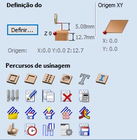
Image16- Toolpaths
For the first stage (Profile Board), I used the first route option called “Profile Toolpath”. For this, I select the external square that surrounds the entire sketch and then the route option. In this way, a new menu of options will appear to add the desired milling parameters, including the type of drill to be used. The depth of cut used for this step will be 2.50mm over the sketch line using a V-Bit drill (90deg 0.25” or 6,35 mm), as shown in the figure below:
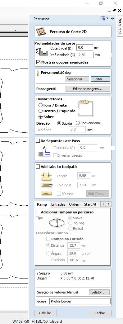
Image17- Profile Toolpath (Profile boards)
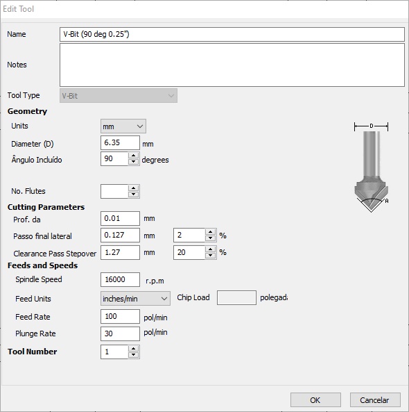
Image17.1- Edit tools (Profile boards)
The same process took place for the second stage (Profile Lines), where I only changed the depth of cut to 1.30mm. For the third step (Pocket Holes), I select the second path option called “Pocket Toolpath”, where the cutting tool will scan a specific internal area of a selected vector. I select the vectors that refer to the overlapping X and 0 and determine the 3.2mm cutting depth, offset and the End Mill drill (0.233” or 5,918 mm).
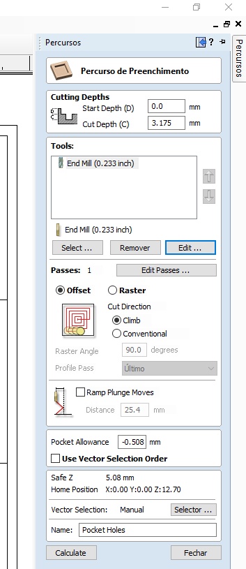
Image18- Pocket toolpaths (Pocket holes)
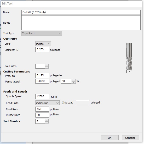
Image18.1- Edit tolls (Pocket holes)
Finally, I create one last path over the external square, to almost completely cross the 15mm thickness of the MDF board used. The cut depth of this path is 14.5mm, off/right of the sketch line, using End Mill drill (0.233” or 5,918mm).
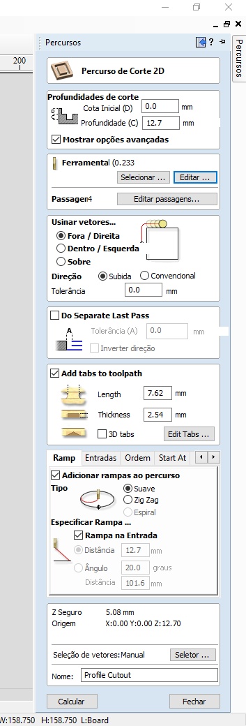
Image19- Profile toolpath (Profile cutout)
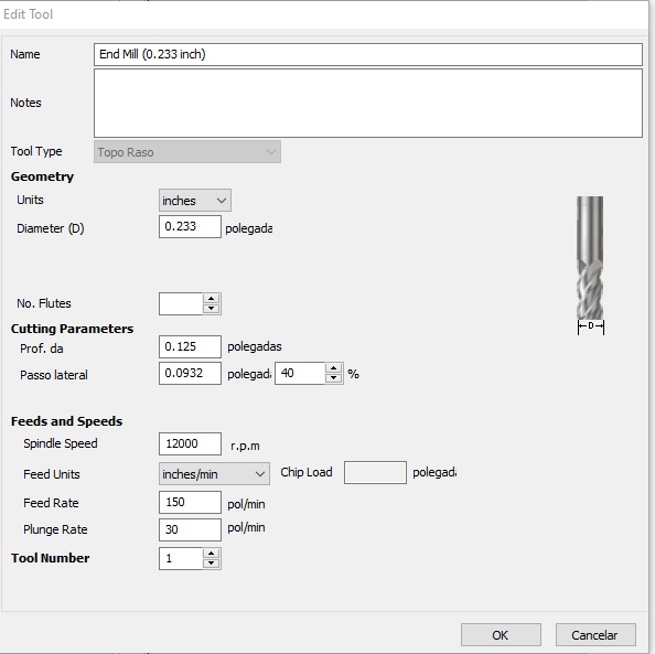
Image19.1- Edit tools (Profile cutout)
It’s possible to change the unit to mm and the software update automatic the others parameters as figure below.
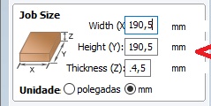
Image20- Inches to mm
After creating the 4 route steps:
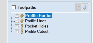
Image21- Creating 4 routes
Now I am going to simulate what these paths looked like after milling. To do this, simply select the option “Calculate” in the menu of route parameters. Once this is done, the following menu will appear:
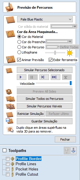
Image22- Path preview
I select the option “Preview selected Toolpath” and repeat the process for all created paths and then I get the following 3D model that simulates the milling of vectorized sketches.
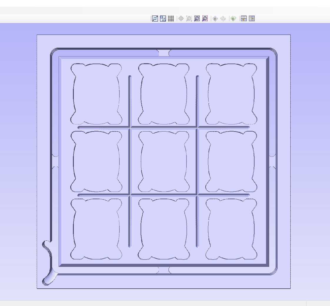
Image23-3D model
It is worth mentioning that the connection points arranged on the four edges of the project’s 3D model are called TABs. Its function is to keep machined part fixed to the MDF board or the raw material used, in order to prevent possible accidents, preventing it from loosening and firing at high speed.
To add TABs to the project is quite simple. Just open the cutting path in which I want to add the TAB, select an option “add TABs to the tool path” and then “edit TABs” and then select the “add TABs” button.
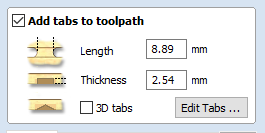
Image25- edit TABs
It is possible to set some TABs parameters
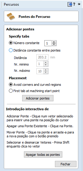
Image25.1- TABs parameters
Using this tool, I can add as many TABs as I think necessary and their arrangement on the projected part. The settings used are shown in the figures above. With that, the final project of my design presents the following simulated form:
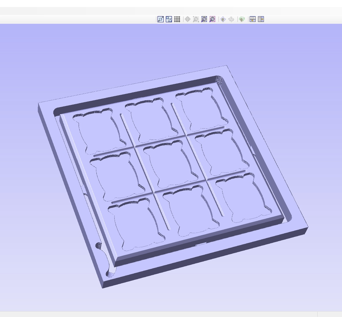
Image26- Final 3D Model
Adding MDF appearance to the model.
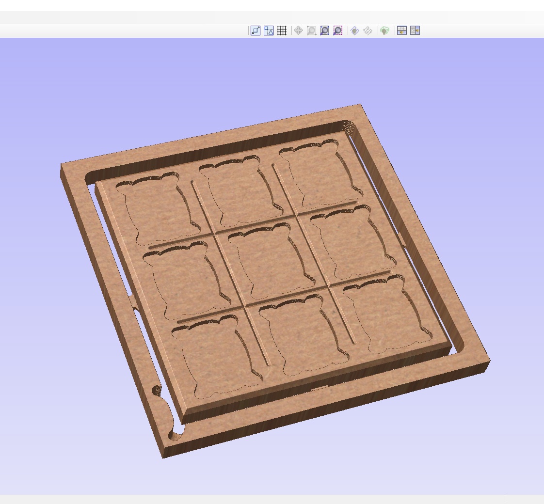
Image27- MDF appearance
I repeated the same processes for the X and 0 pieces. The machining parameters were basically cutting paths using V-Bit (90deg 0.25”) and End Mill (0.233”) drills The configurations used for machining the X pieces are shown below:
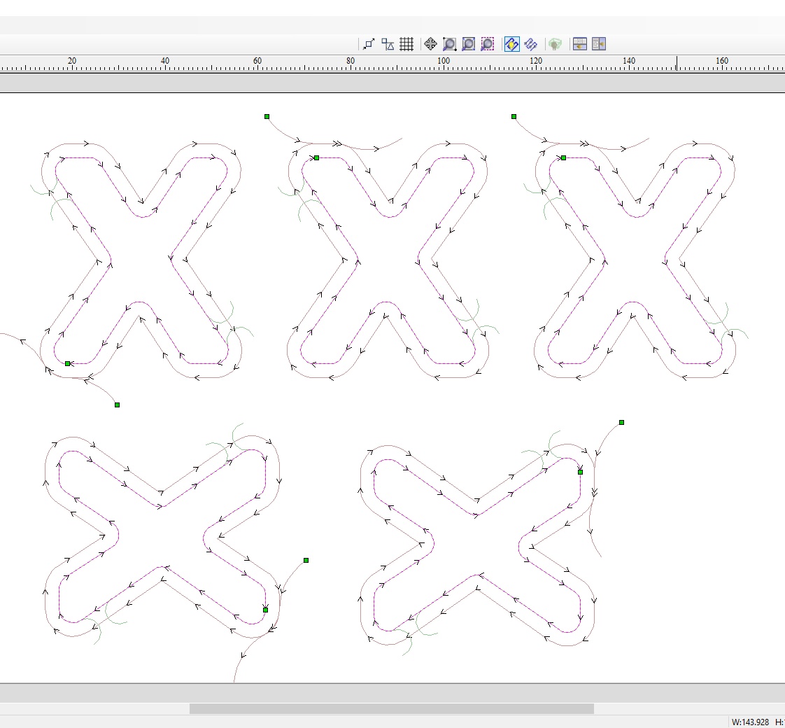
Image28- X cutting path
- V-Bit (90deg 0.25” or 6,35 mm) - cut - 1.27mm deep.
- End Mill (0.233” or 5,918mm) - cut - 15.00mm deep.
And the settings used for machining 0 pieces:
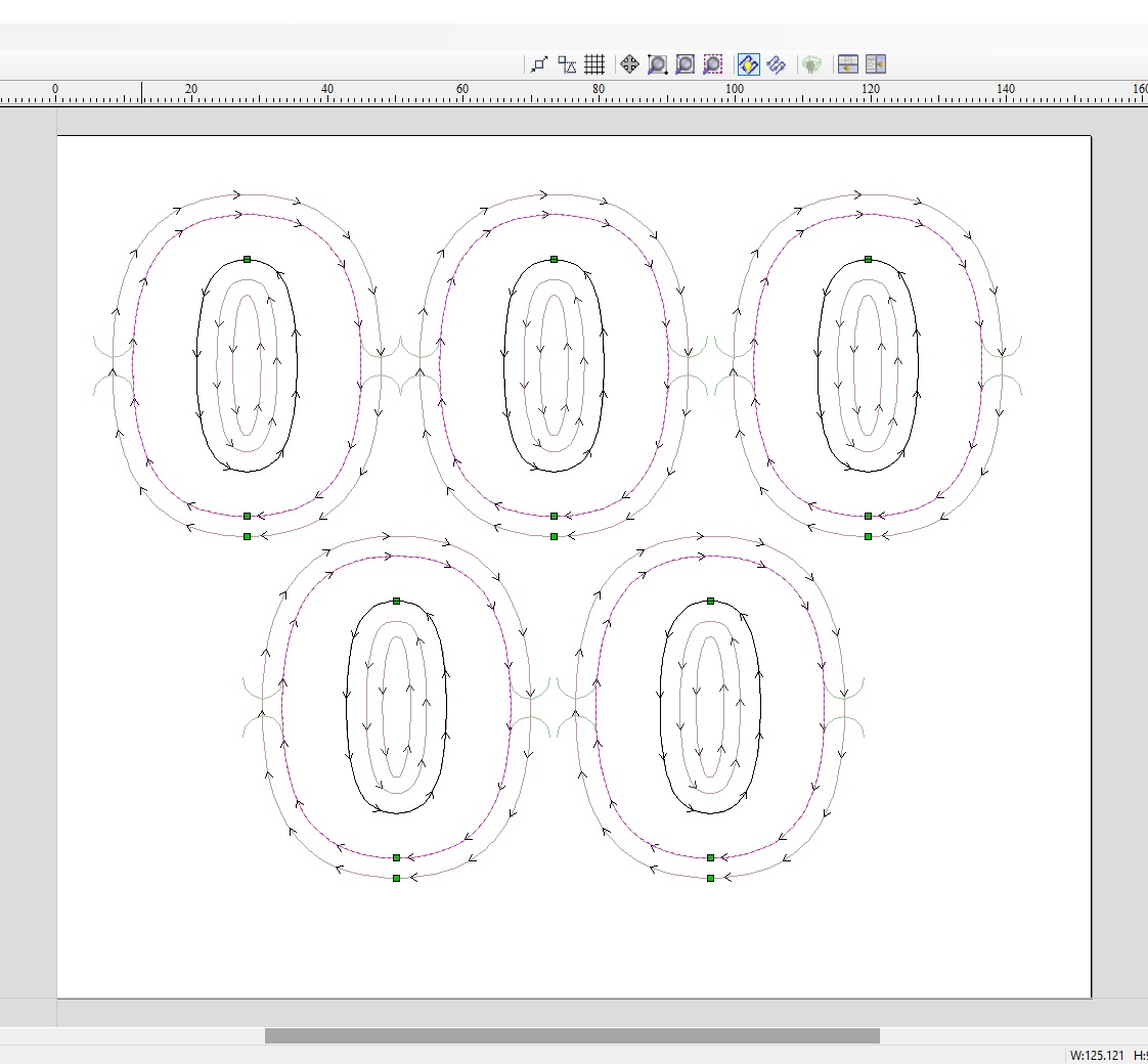
Image29- 0 cutting path
- V-Bit (90deg 0.25” or 6,35 mm) - cut - 1.27mm deep.
- End Mill (0.233” or 5,918mm) - padding - 15.00mm deep.
- End Mill (0.233” or 5,918mm) - cut - 15.00mm deep. The next step will be in the operation of the CNC machine for making the part.
So has I told before the design built for this week’s activity was based on a free testing model from Vectric. The shapes remained, but I made many changes in their composition, mainly in the construction of the machining paths. I rebuilt the machining paths, changing their working parameters, such as the cut and fill thicknesses, to use the MDF and the drills that I have in the laboratory.
Manufacturing
CNC machine
In the laboratory we use the CNC ShopBot Desktop D2418. This machine is an excellent CNC milling machine for working on wood, plastics, aluminum, and other carpentry raw materials in general.
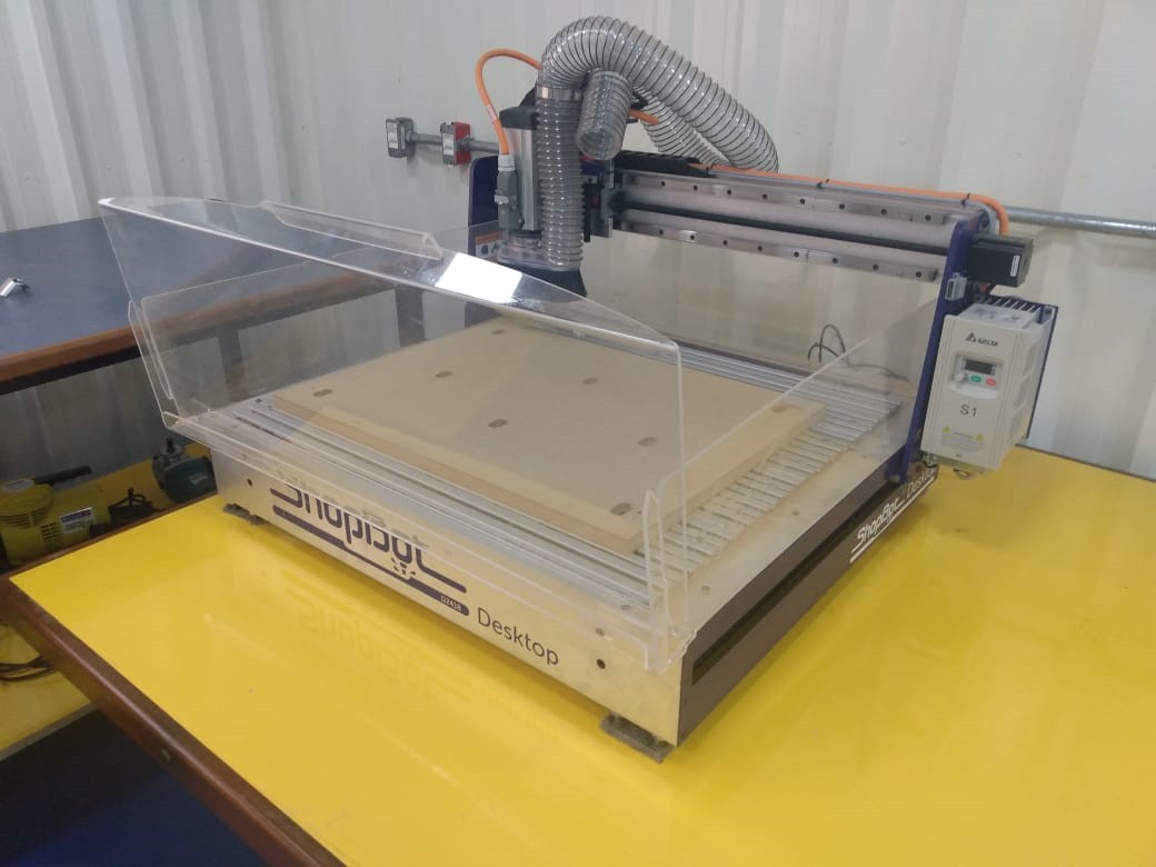
Image29- CNC ShopBot Desktop D2418
The maximum working dimensions and other technical specifications can be seen in the following table:
| Parameter | |
|---|---|
| XYZ Movement | 640 mm x 508 mm x 139,7 mm |
| Weights | If crated, add 178 lbs. 103 lbs [no deck, no cutter] 148 lbs [total weight with aluminum deck and spindle] 170 lbs [total weight with universal hold down deck and spindle] |
| Crate Dimensions | 44.5” x 55.75” x 37.5”, weight: 220 lbs, loading dock, forklift or lift gate service is recommended |
| Collets | Includes one 1/4” and one 1/2” desktop collet and collet nut (ER20) |
| Cut Speed | 100mm/s |
| Jogging Speed | 150mm/s |
| Resolution | 0,00635mm |
| Electrical System requirements | 120 V @ 15 amperes |
Personal Protective Equipment (PPE)
When working with wood, many of the particles that are suspended in the air can be carcinogenic. That is why it is important to work with the necessary safety elements to prevent accidents at work and in the long run. The main PPE used in these wood activities are:
-
Mask: Avoid the inhalation of dust, sawdust particles suspended in the air and toxic particles through the airways. There are 2 types: maintenance free (disposable) and low maintenance, which have special filters for replacement.
-
Gloves: Protect the worker’s hands. Especially in sawmills they must be resistant to protect the hands against possible cuts.
-
Transparent glasses: Protect the eye area against dust, sawdust and particles suspended in the air.
-
Hearing protector: Protect the ears from noise coming from the equipment, common in sawmills.
-
Apron: Made with material resistant to organic solvents and possible cuts.
-
Boots and / or closed shoes: They must be waterproof, preferably high-top, in addition to being resistant to organic solvents and possible falls from sharp or piercing objects.
Operations Menu
For the operation process of the ShopBot Desktop D2418 CNC machine, I used the ShopBot3 software. This software came on a USB stick with the machine for installation. When I start ShopBot3, an operations menu will appear (ShopBotEASY) where I can create a point of operation on the X, Y and Z axes to be the starting point (0,0,0) and select path files made in Cut2D or other software in the Vectric line for preview and cut.
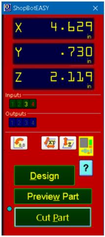
Image30- Operations Menu
Thus, the first step is the creation of a starting point (0,0,0). For this, I add the drill that will be used in the operation to the machine.
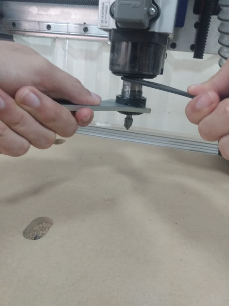
Image31- Ajusting the drill
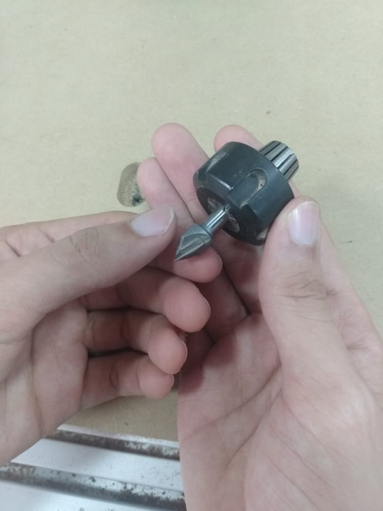
Image31.1- Ajusting the drill 2
The machine has, as an indispensable accessory, a metal plate that acts as a height sensor for the zero point on the Z axis. The plate was connected to the machine as shown below.
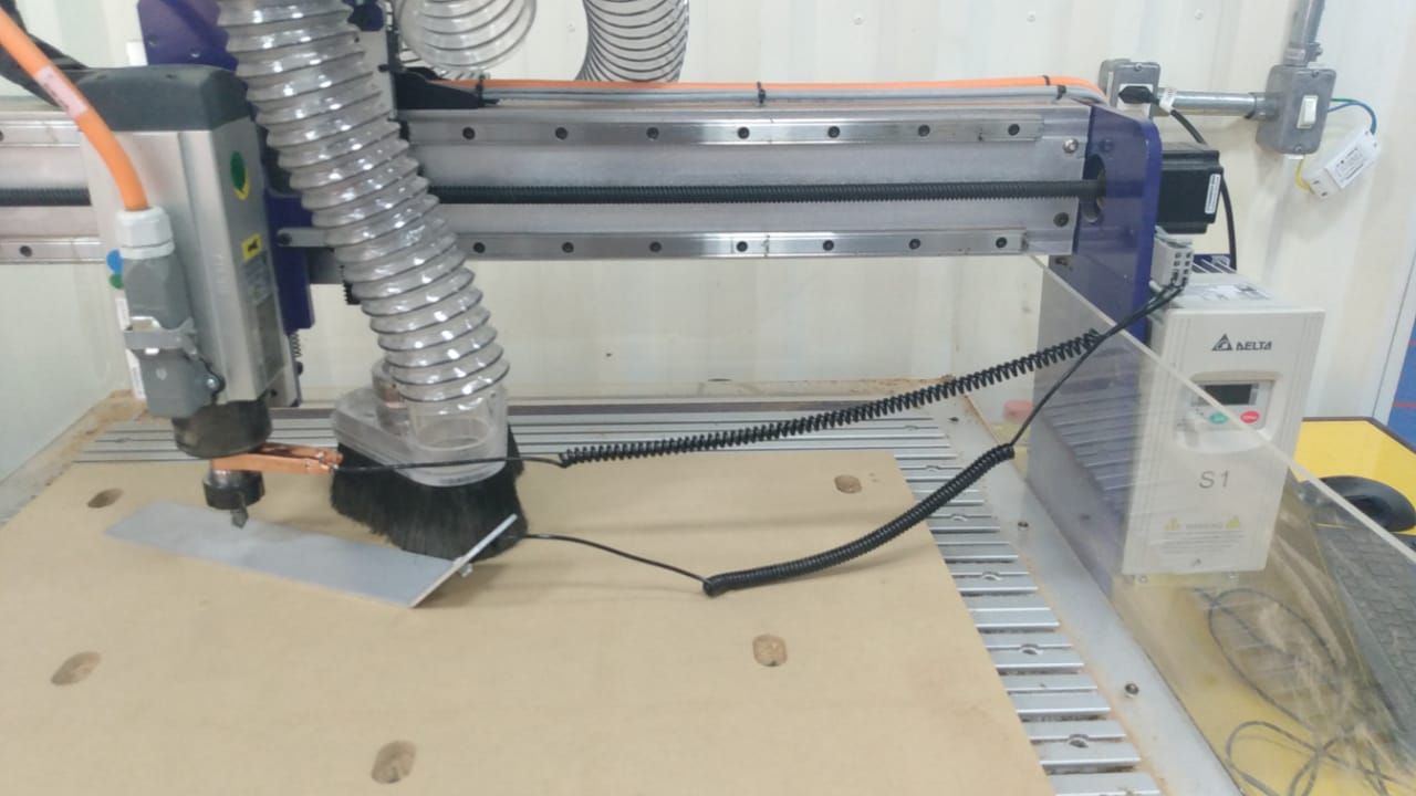
Image32- Ajusting Z axis
Then I select the “Z” icon in the operations menu and “ok” to execute. Thus, the carriage will descend along the Z axis until the drill touches the metal plate, closing the circuit, and determining the height of the zero point. The process for determining the zeros on the X and Y axis is simpler. I select the yellow joystick icon in the operations menu and move the cutting tool to the position that I think is appropriate to start work. That done, I select the option to reset the position, and now I have a zero point on the X, Y and Z axis.
Machine Preparation
The material used was a white MDF board with dimensions of 600x400x15mm. First, I place the MDF and screw it into the base. I used an electric drill to make holes in the plate and then added screws for fixing. This must be done to prevent the board from moving when cutting at high speed. If the MDF is not fixed to the base, the workpiece can get loose causing an accident.
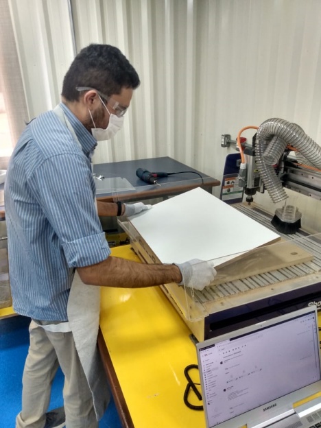
Image33- Positioning the MDF board
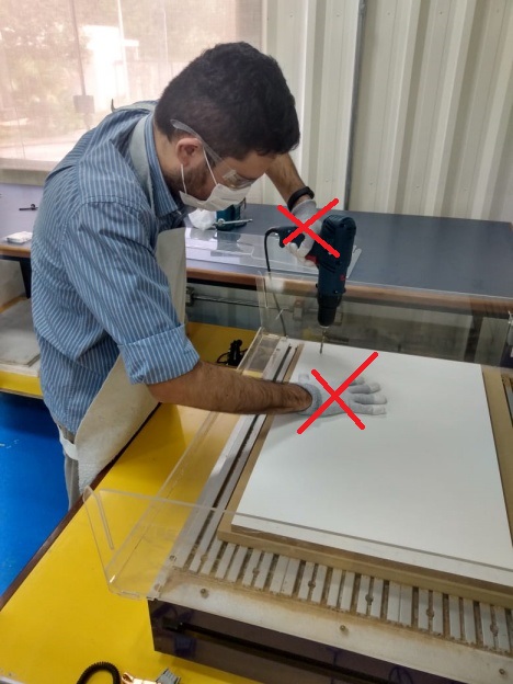
Image33.1- Doing it the wrong way
Note: DON’T use gloves in rotating machines as the ShopBot. My mistake :)
Now just save the design file as a route file in the “ .sbp” format required by the machine, select the “cut part” button from the operations menu and choose the route files in the order that I want it to be operated.
Machine Test
A good way to do a great project is to understand the operation of the machine and its limitations, so I created a simple square sketch with 90° angles without any kind of rounding.
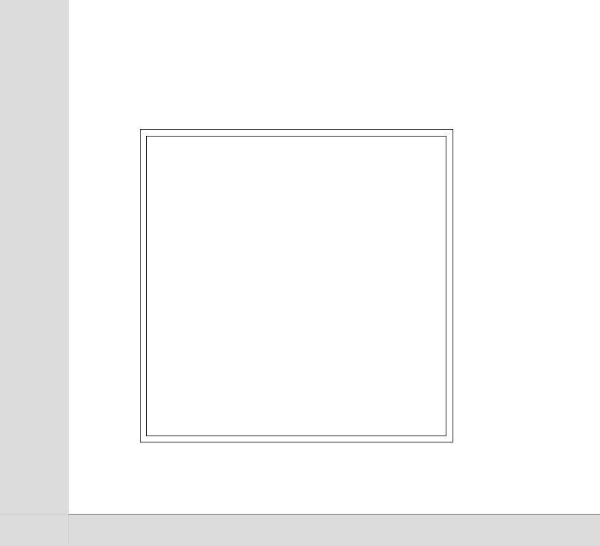
Image35- Model for the test
I only used cutting milling to evaluate how the machine would behave, and obtained the following parts:
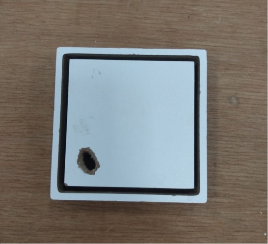
Image36- Test 1
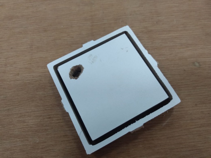
Image36.1- Test 2
Through these results I was able to reach the conclusion that the machine can only make angles of 90° in external cuts. In internal cuts the drill tends to round the corners. In addition, due to the white layer that covers the MDF, I needed to add an additional 0.2mm in the thickness of the project so that the drill bit would pass through all the material facilitating the removal of the plate. I also concluded that the project would need to be sanded to remove the fixing TABs. Note: the hole on the part of the figure above already existed before the test. I used this little piece in the test because it would be discarded.
Final Set milling
Below is the videos of the cutting milling process done in the laboratory.
The hashtag part
The insertion location of the 0 and X
The 0 and X
Complete set
The results of the cut are shown in the following images:
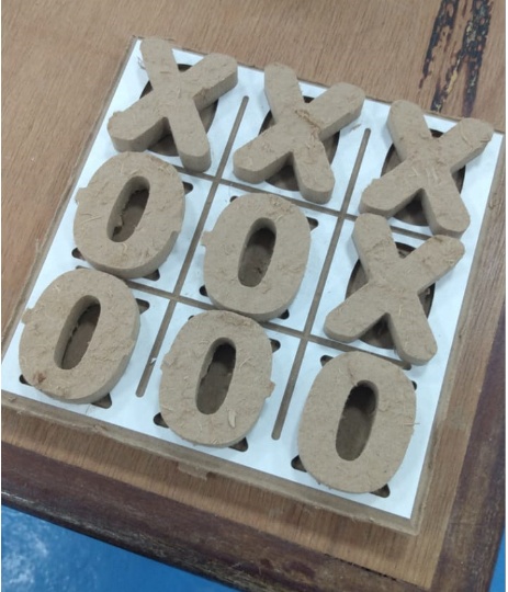
Image37- Set complete
As we can see in the image above, the pieces need to be sanded and painted to seal the wood, since MDF is a material that releases a lot of waste. So, after sanding all the pieces and painting them, I got the following final design result:
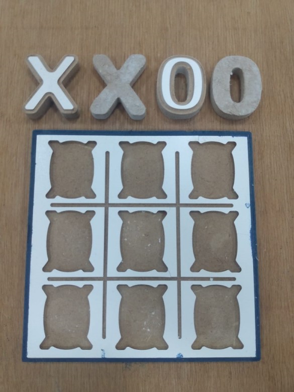
Image38- Set complete 2
Group Assignment
- Do your lab’s safety training.
- Test runout, alignment, speeds, feeds, materials, and toolpaths for your machine.
Tests
To machinate the tests, I followed the tutorials in the machine’s instruction manual using VCarve Cut2D extension. This is the software chosen and recommended by the manufacturer to operate the ShopBot Desktop D2418 CNC machine. Basically, we need to enter the material thickness, the tool diameter and the tool paths, and the operations menu software itself calculates the best combination of the operating parameters. The machine used has a display that has options to start, stop and adjust the spindle speed. The spindle speed is automatically set by the software before the work operation is started, however the operator can change it using the display.
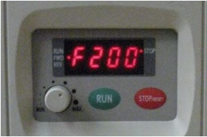
Image39- ShopBot Display
The spindle speed is automatically configured by the software, showing the following message below before the start of the work operation, however the operator can change using the display.

Image39.1- Start spindle alert window
Even though I have the ideal parameters, I wanted to test possible combinations, varying according to the table below.
| Display | Spindle RMP |
|---|---|
| 300 | 18k |
| 266 | 16k |
| 233 | 14k |
| 200 | 12k |
| 166 | 10k |
| 133 | 8k |
| 100 | 6k |
To send the generated files, ShopBot3 was used. This software is provided by the supplier to control the machines. It has no CAM function, but it controls all commands to perform the work with the CNC. I made a piece like the one from the final project so that the cutting tool could make a filling path, and obtained the following results:
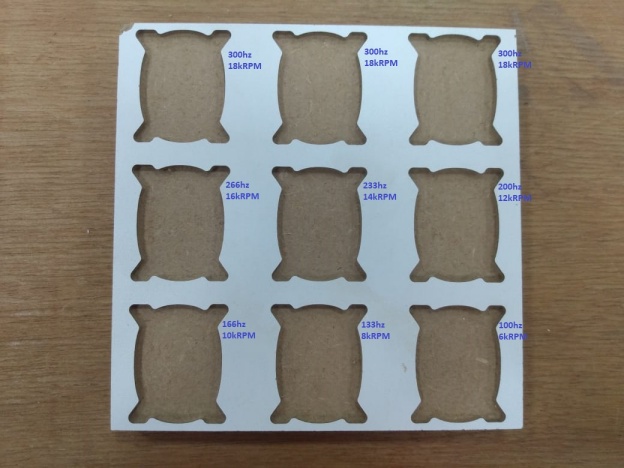
Image40- Result of the tests
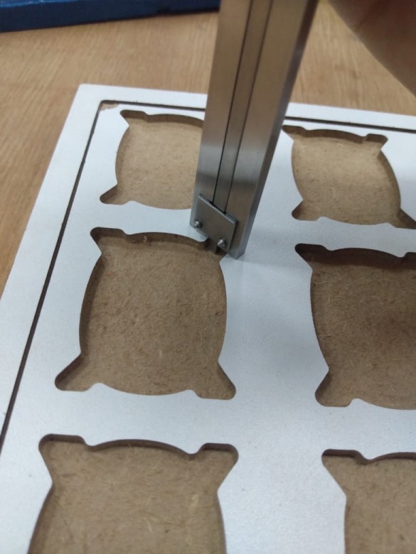
Image41- Measuring the holes
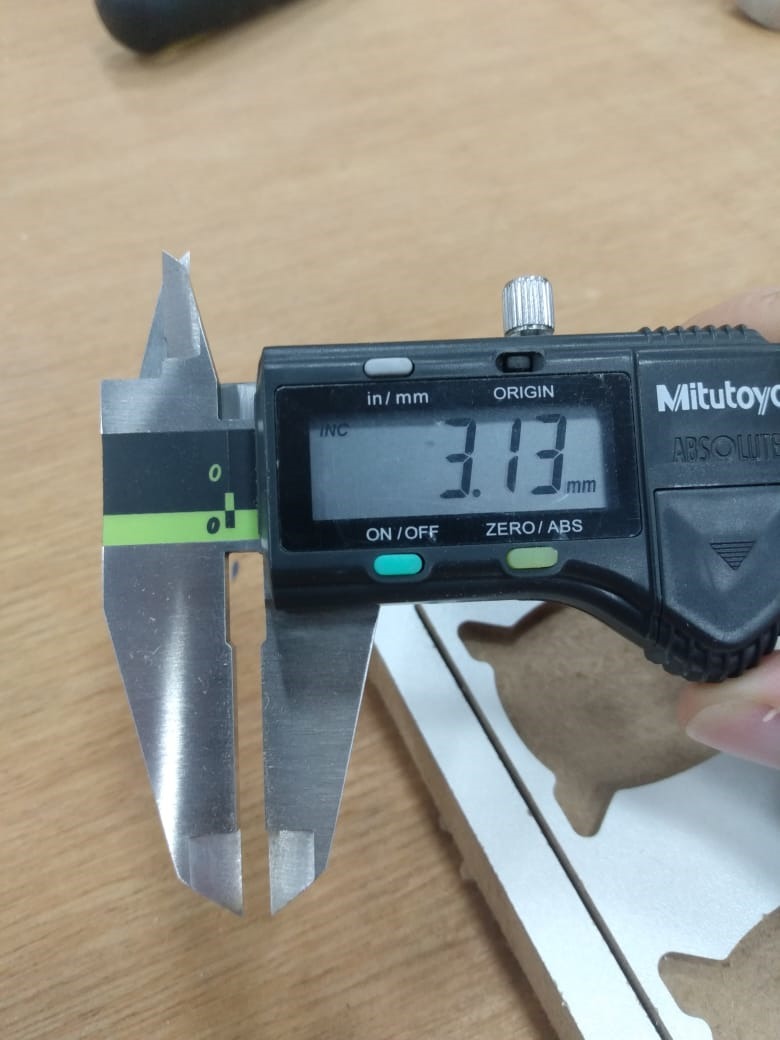
Image42- Result of the measure
The chip production and milling time were the factors that I used to define the best results, found in the range of 200-266hz (12k-16kRPM). What had already been predicted by the machine’s operating software. All results were perfectly accurate, without damaging the edges of the material since the cutting tool used was new. To test the kerf of the machine I used the part already machined in the initial test of the machine, since it consists of two centered squares.
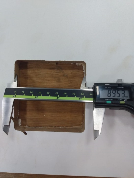
Image43- Kerf test 1
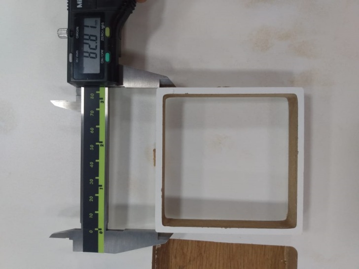
Image44- Kerf test 2
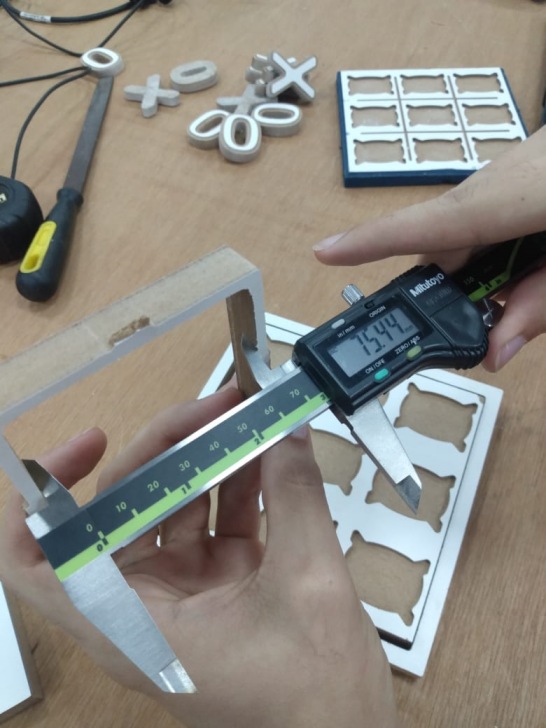
Image45- Kerf test 3
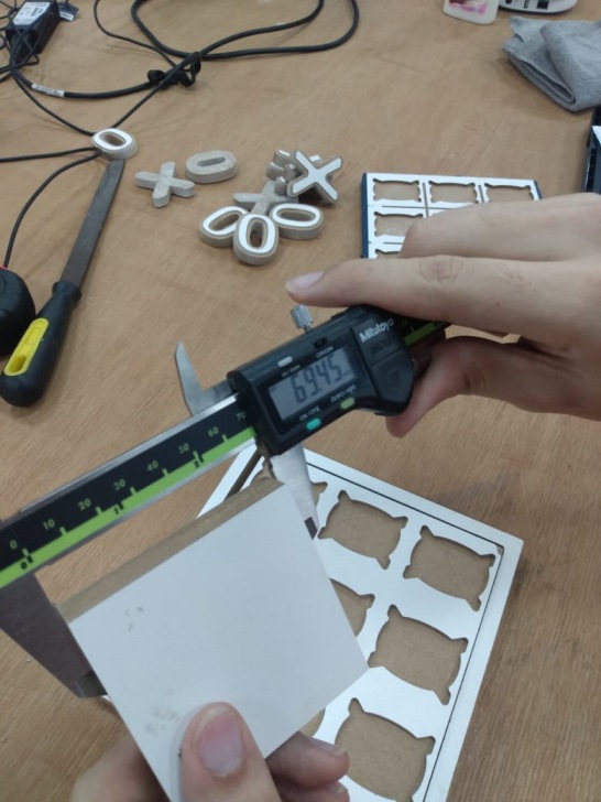
Image46- Kerf test 4
Based on the gauging of the measurements of the cut parts, I obtained an average of approximately 6.36mm of material lost in machining. The obtained value was already expected since the cutting tool used has a diameter of 1/4 “(6.35mm). I repeated the process for two more similar pieces, and I concluded that the kerf will always be an approximate diameter value of the cutting tool, however this value may vary depending on the raw material used in machining.
Dogbones milling
I had a meeting with my international evaluator and we have a very nice chat how to improve this week adding information about “How to make dogbones milling”. Source
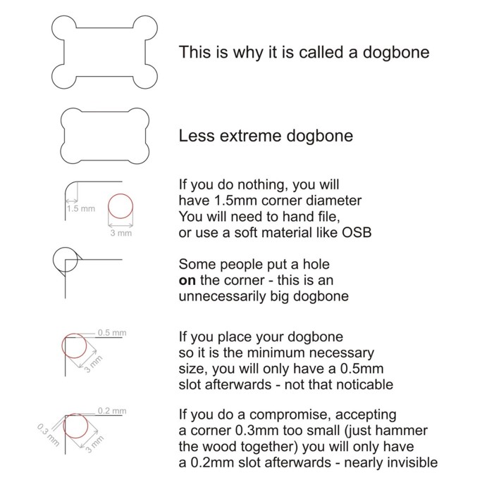
Image47- Examples of dog bones.
As shown in the figure above, by taking the tool just to the corner, you can make quite unobtrusive dogbones. If you take the tool just 0.3 mm shy of the corner, you can make almost invisible dogbones - this no one else seems to be doing. It often even has the advantages that the friction holds your join well enough that you do not need to glue it, or can hold while you are gluing it. Another solution is to hand file the inner corners square (we do that quite often - it is quite quick - if one is only making one of something, it takes no longer to file the 1.5mm radius inner corners square than it takes to draw the dog bones). So, we mainly draw dogbones if we are doing several of something and manufacturing time is an issue. Source
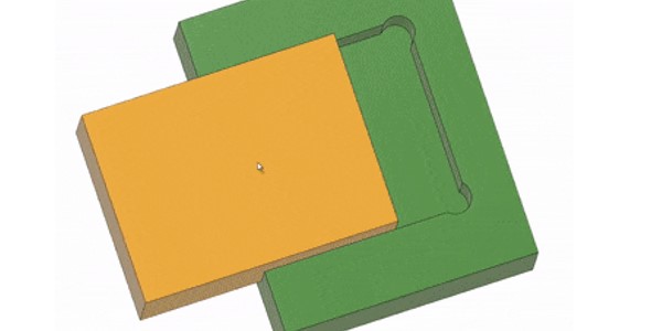
Image48- Dog Bone Snap.
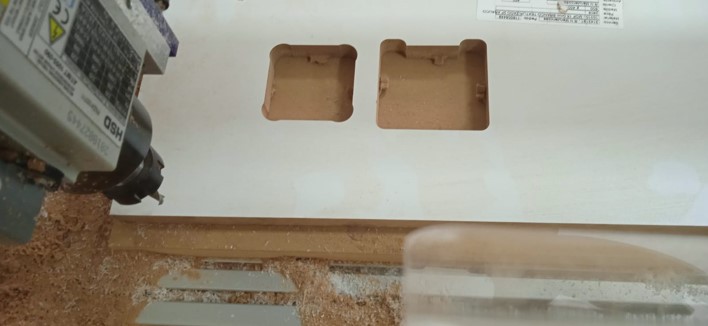
Image49- Dog Bone Snap.
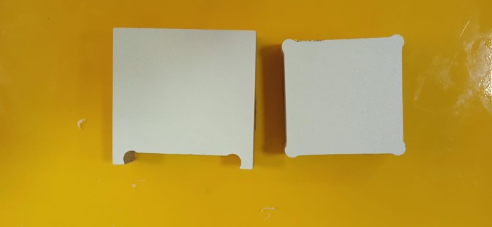
Image50- CNC cut parts using the dog bone milling for fitting.
Using the equation found at the FabAcademy website of Joseph Paul that shows that the dogbone fillets are parametric and their radius are calculated as 1/1.9 * tool diameter in order to leave just a little tolerance so the CAM processor doesn’t ignore those areas. We can see that the dog bone milling was a success and the fit was perfect as seen in the figure below.
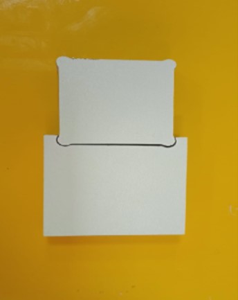
Image51- Testing the fit of the dogbone milling.
Conclusions
This was a fun week that I have the opportunity to make a toy to play with my son and I learned a lot about Computer Controlled Machine.
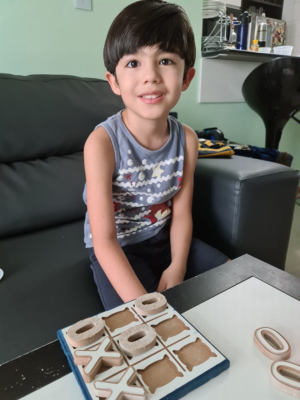
Image52- My son having fun with the new toy
Unfortunately due to the Covid-19 pandemic and having a laboratory with homelab characteristics it was not possible to do something “big”, however, the “make” part was done (design + mill + assemble), in the future I will replicate this activity but on a larger scale
- All the files done in this week assignment can be find in the repository