13. OutPut devices
This week I’m making a peristaltic pump to add nutrients solution for my hydroponics final project., I ended up changing my final project, still, the pump was a fun build and experiment with.
Research
the peristaltic pump is a simple pump, where a tube is being squeezed to move liquid using a roller moved by a motor, its main advantage is easily precise volume control, but it has a low flow rate, which is acceptable.
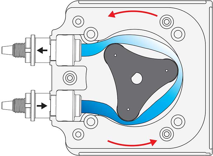
The pump I am building will be designed and build using 3D printing, the actuator will be a stepper motor to be able to pump precise volumes of a liquid.
A Stepper motor is a motor constructed from a magnetic rotor, and by controlling the current direction on the stator, the rotor magnet gets attracted to the opposite pole and moves at a fixed angle at each step. By using a stepper motor driver, the current in the stator coils can be controlled to achieve continuous motion, and by using a microcontroller to count the steps, the angular displacement can be calculated to know exactly the rotor travel motion.

design and manufacturing
Hardware design and production
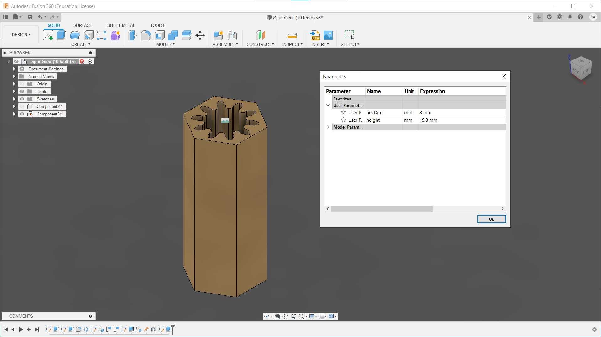
I will be using this design from Thingiverse as my pump, the design is parametric so I can tweak it to my liking easily, the design uses openscad which is a programming based CAD design software, the software is light and editing the parameters was easy as the design is clear and has comments and instructions about editing the design.
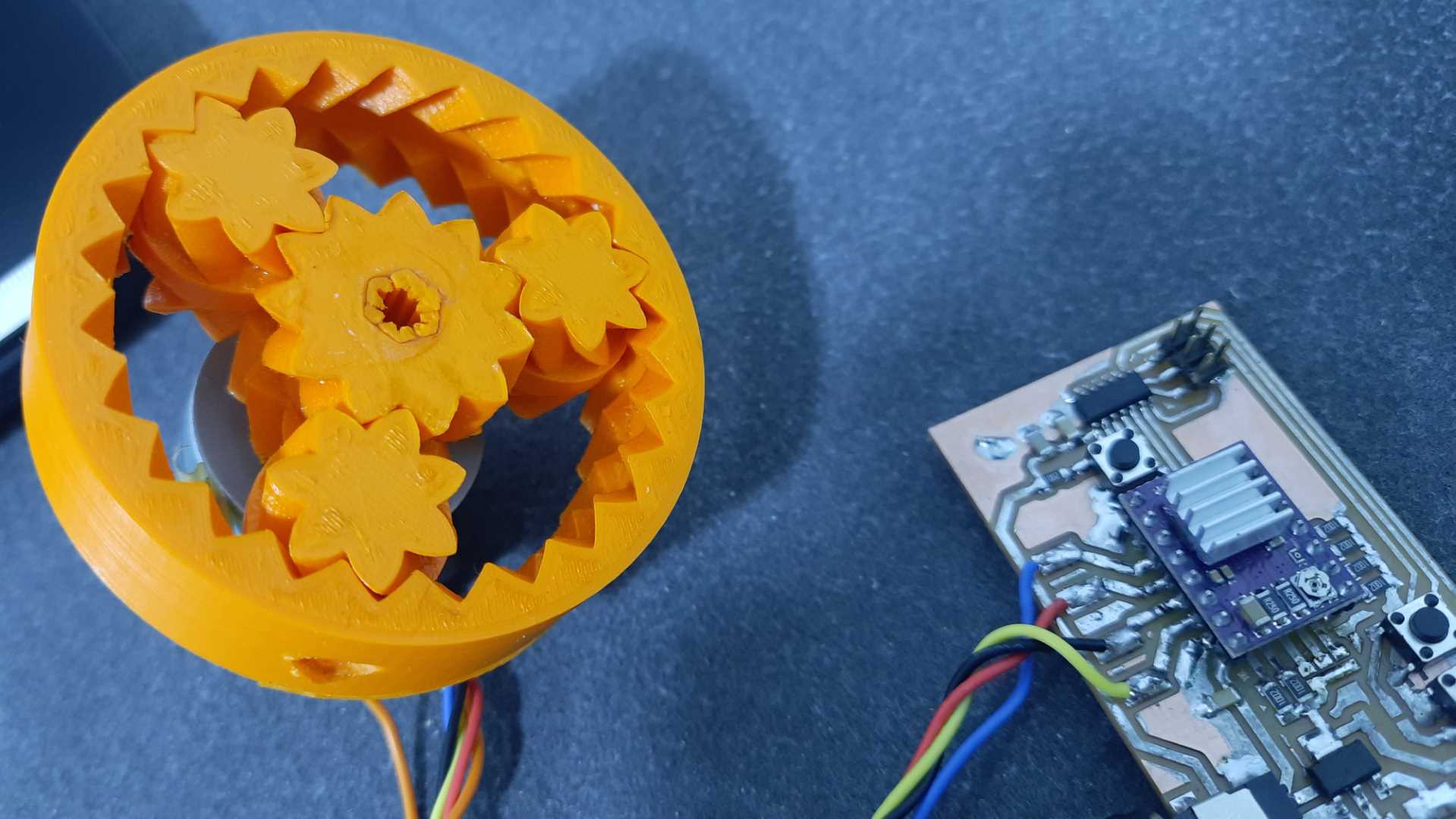
After picking the parameters and printing the pump, I designed and print a mount to fix the pump to a stepper motor and a coupler to connect the motor shaft to it.
coupler deisgn
mount deisgn
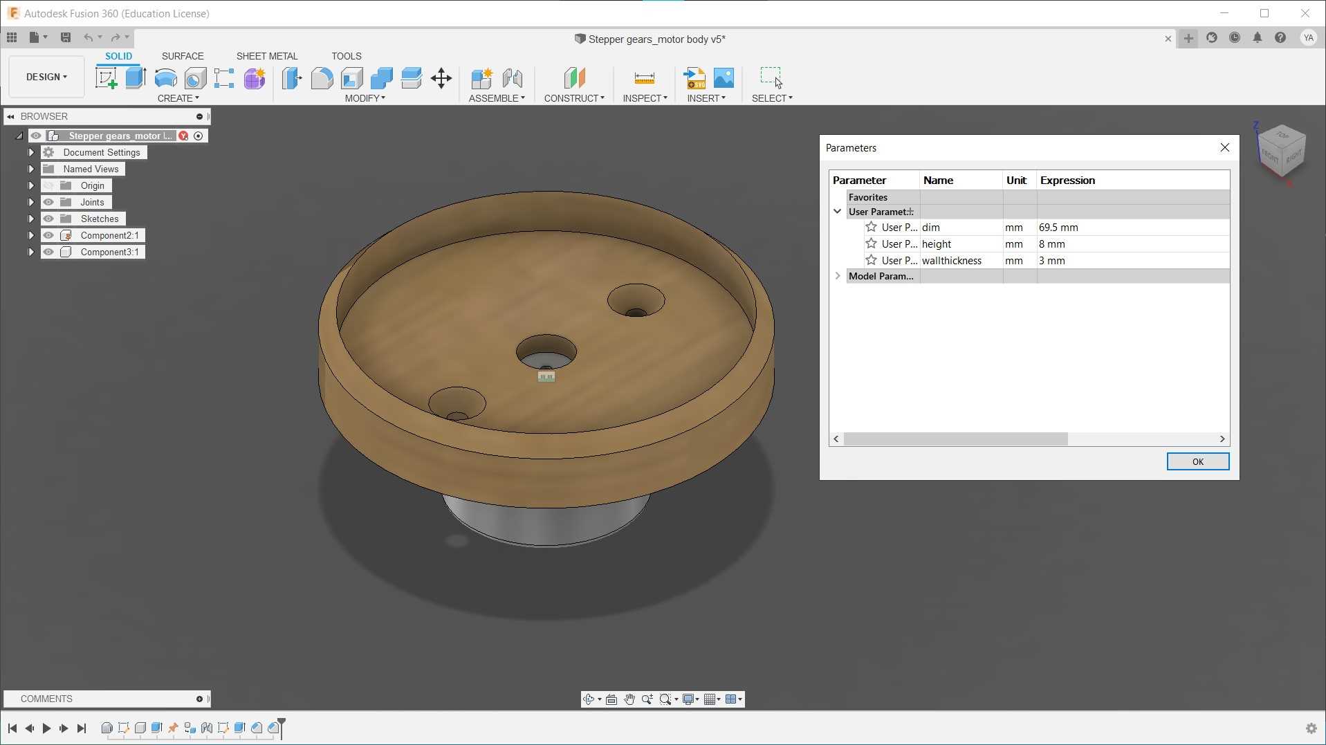
pump deisgn
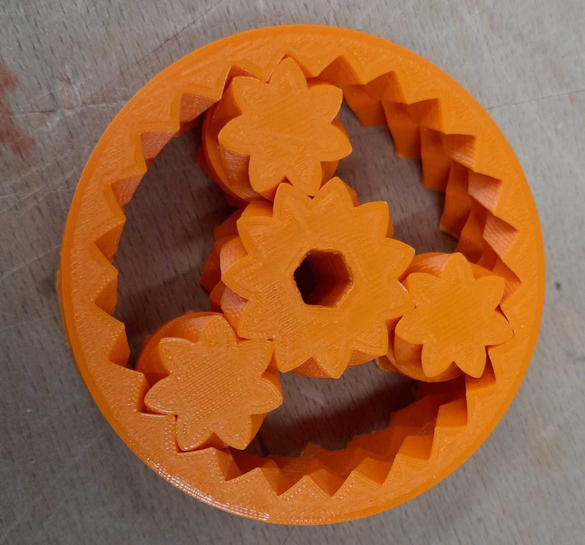
final assemble
Electronics design and production
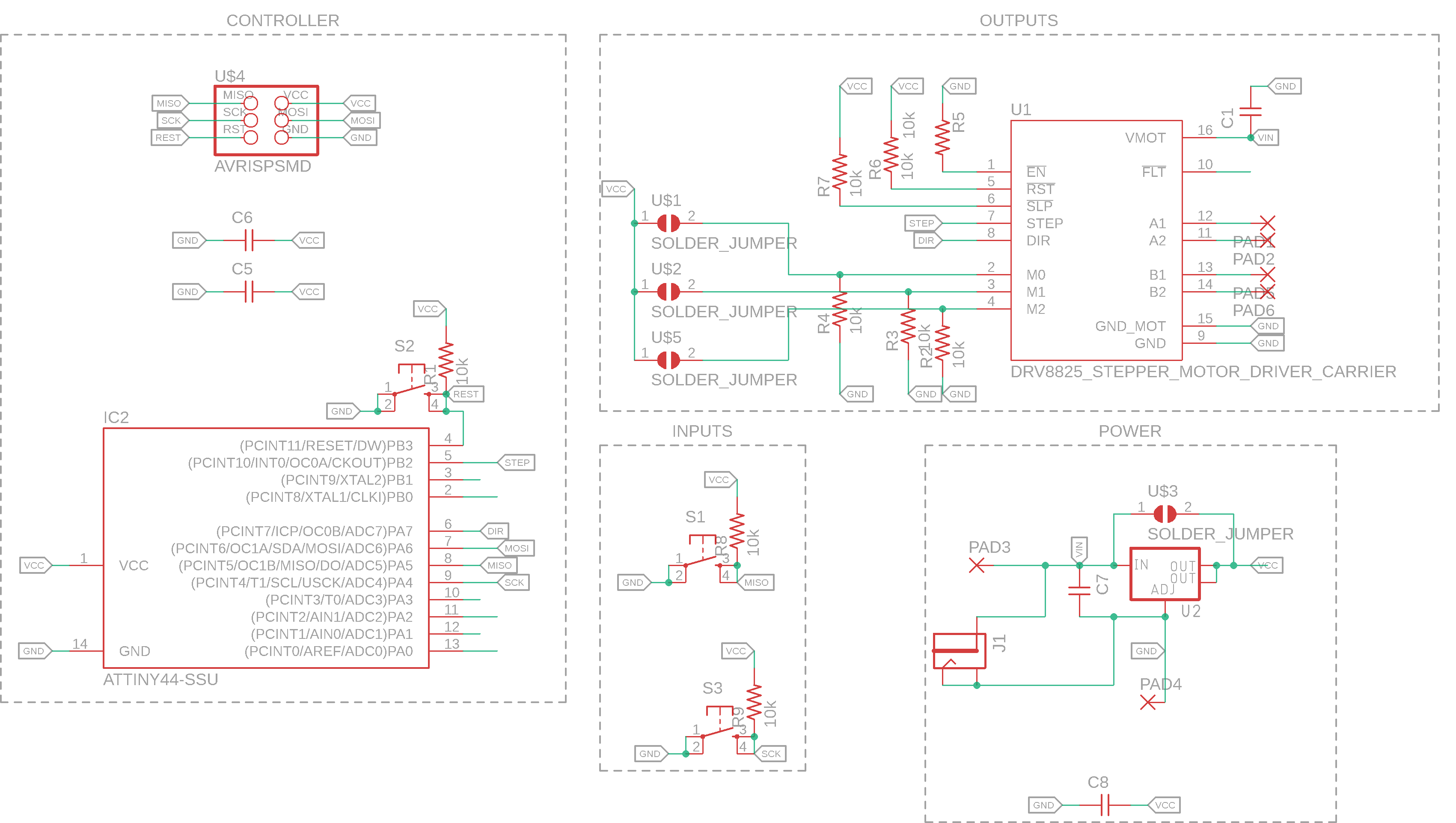
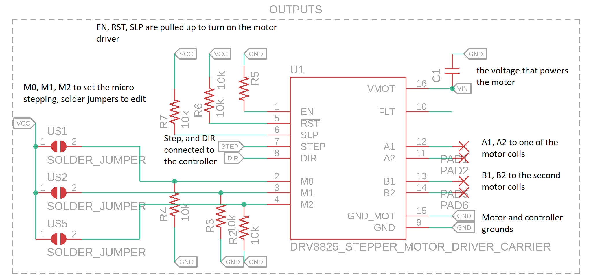
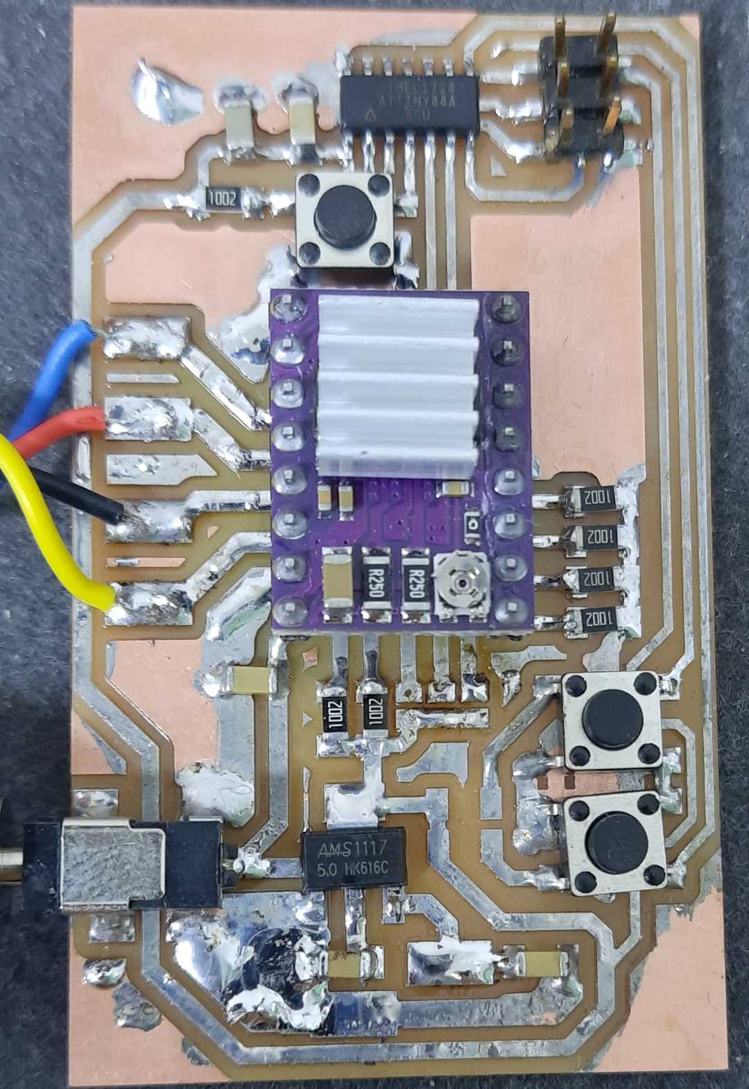
I’m using a stepper motor to precisely control the volume, I design a simply microcontroller-based PCB that has the Attiny44 in its heart, and uses the DRV8825 driver module, which is a stepper motor driver that connects to the stepper motor stator coils, and uses a simple STEP/DIR interface. by pulling the DIR pin up the motor should travel clockwise, and by pulling it down the motor should travel counterclockwise. After setting the DIR pin, with each HIGH pulse on the STEP pin, the motor should move one step to the set direction. The DRV8825 is capable of micro-stepping, which utilizes PWM to move the motor in smaller steps; it can move a whole step, half step, 1/4, 1/8, 1/16, or 1/32 step with each pulse, which gives the motor a smoother motion with less vibration but can result to a weaker holding torque.
the PCB has a power input jack that would be the power source for the motor, a voltage regulator to step down the voltage to power the control electronics, 2 programable push buttons connected to the attiny44 to test the motor connected to it in 2 directions.
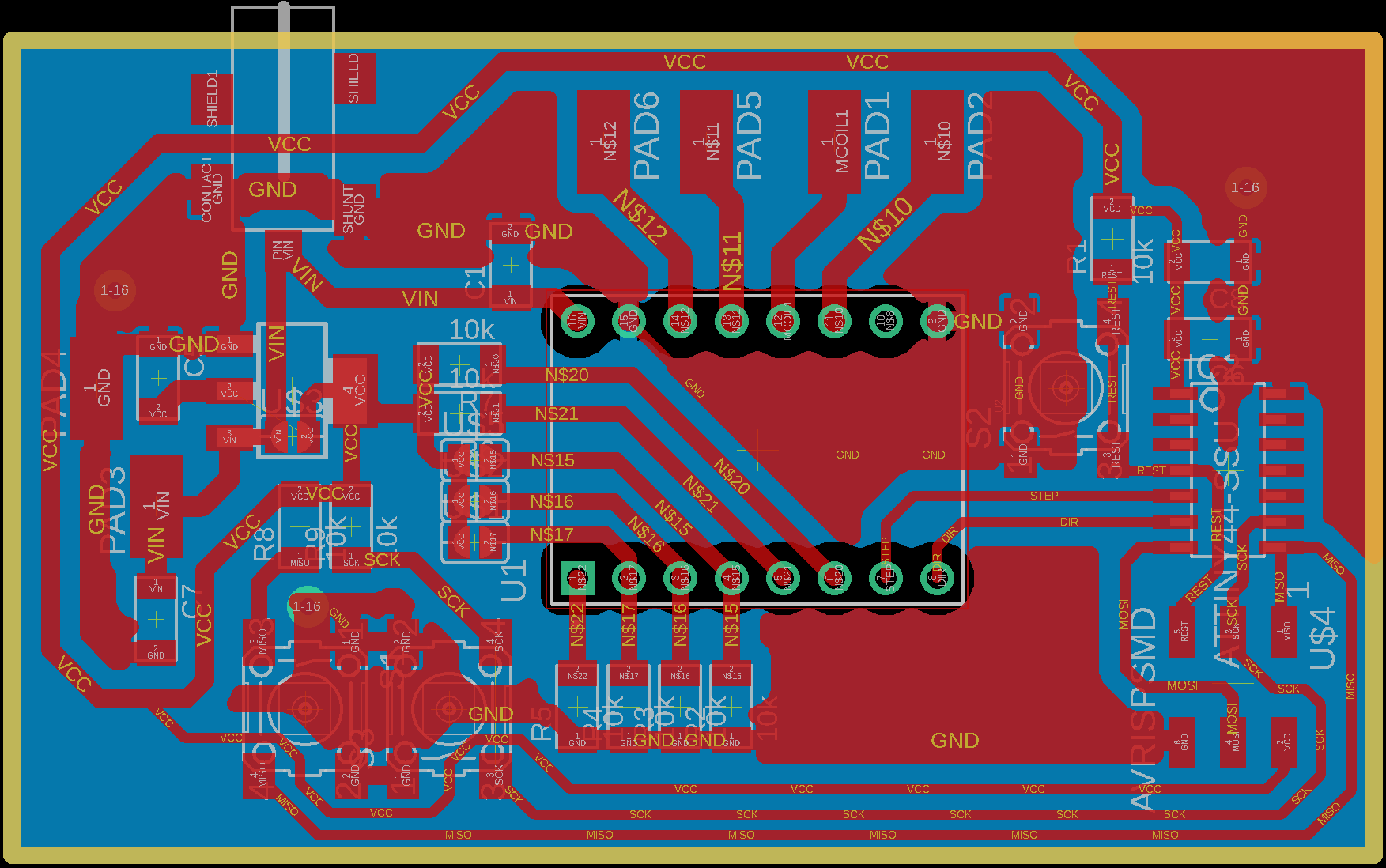
the PCB uses a two-layer design, where the bottom layer is just a ground plan to make routing easier, but to avoid short circuit I sanded the couple around the driver through-hole pins so that they won’t short to ground.
PCB schematic
PCB board layout
fianl results
programming and testing
to test the project I uploaded the simple test code in the tutorial, the PCB works well and can make the pump turn. video
the test code sets the direction clockwise, moves the motor 200 steps, pauses for a second then sets the direction counter-clockwise, and moves the motor 200 steps, pauses for a second then repeats.
Here is another video testing the motor without the pump installed.
code
// Define pin connections & motor's steps per revolution
const int dirPin = 7; // the pin connected to the direction pin of the driver
const int stepPin = 8; // the pin connected to the steps pin, the motor moves one step with each high pulse
const int stepsPerRevolution = 200; // number of steps to move for the test

void setup()
{
    // Declare pins as Outputs
    pinMode(stepPin, OUTPUT);
    pinMode(dirPin, OUTPUT);
}
void loop()
{
    // Set motor direction clockwise
    digitalWrite(dirPin, HIGH);

    // Spin motor clockwise slowly
    for(int x = 0; x < stepsPerRevolution; x++)
    {
        digitalWrite(stepPin, HIGH);
        delayMicroseconds(2000);
        digitalWrite(stepPin, LOW);
        delayMicroseconds(2000);
    }
    delay(1000); // Wait a second

    // Set motor direction counterclockwise
    digitalWrite(dirPin, LOW);

    // Spin motor counter-clockwise quickly
    for(int x = 0; x < stepsPerRevolution; x++)
    {
        digitalWrite(stepPin, HIGH);
        delayMicroseconds(1000);
        digitalWrite(stepPin, LOW);
        delayMicroseconds(1000);
    }
    delay(1000); // Wait a second
}
but once I added the tube the motor couldn’t make the pump turn anymore, so I connected the pump to a power drill to test it, and it works well.video
for the final project, I should either experiment with the pump parameters, reduce the tightness of the rollers on the tube and see if it would work well, or change the motor to a strong gearbox DC motor.
I ended up changing my final project idea and did not need the pump for it, the concept works and it is easy to implement, but as mentioned before for the pump to be able to move liquids it needs a stronger motor, or to play with the pump design paraments so that the motor won’t have to use too much torque.
Group assignment
This section is about the Group assignment, I will measure the power going through the board I made, I used a bench power supply to set the input voltage to 12V DC, the power supply is connected to the PCB through a power jack. The lab’s power supply enables me to set a current limit, and once I turn the output on the lab bench power supply shows the drawn current. The drawn current represents the torque needed for the motor to move, from voltage and current I can calculate the power consumption.
video lab bench power supply reading.