14. Networking and communications
This week I worked on networking and getting microcontrollers to talk with each other. In project A I want to explore RFID tags, the main goal is to make the RFID tags set a project into different operation modes, which gives the advantage of giving control to the tag’s owner. In project B I will build a communication bus, where multiple devices can be connected to a UART network, the devices on the network should only enable the RX pin and keep the TX pin disabled, devices will wait for a cue, the cue can be a unique byte for each device. Once a device receives its cue it can respond after getting the needed data, and after it is done sending data it should disable the TX again so it won’t interfere with other communications
Project A RFID communication
RFID uses an electromagnetic field to identify transceivers attached to objects like tags, the transceiver is triggered when it is placed near an RFID reader device. the transceiver sends digital data that includes the tag unique ID followed by the content of its memory. an RFID tag memory can be read and rewritten.
In this project I will have an RGB alongside an RFID reader, when a tag is placed on the reader, the RGB will turn on with a color set by the tag.
The MFRC522 chip is the heart of the RFID module that I am using, the chip has SPI, Serial UART, and I2C-bus interface, to communicate with a microcontroller.
The module I purchased has an SPI interface, my PCB design will connect it to a microcontroller through SPI, and connect the microcontroller to a computer using serial UART.
PCB design and manufacturing
I started designing a PCB with an ATmega328p connected to the RFID module, the ATmega will communicate with the reader using SPI, and the module is connected to the ATmega as recommended by the library page, I added FTDI pin headers and an RGB LED to try out multiple color configurations.
SPI is a serial synchronous communication protocol, it uses a master-slave architecture. the architecture naming is associated with slavery and people agree that it must be changed but have not agreed on an alternative yet, I will be referring to the naming as master/puppet. The SPI protocol uses a clock signal shared by all devices on the network. The master initiates the communication, and the puppet responds based on what it is programmed to do. the library I am using handles the SPI communication, and I use object instance commands on the code to get and send the data I need.
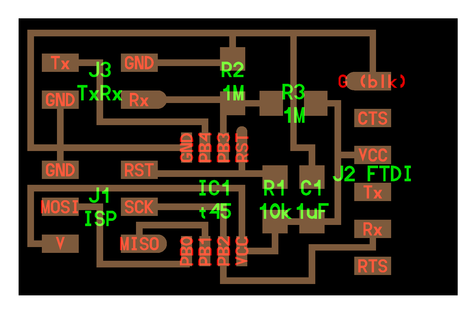
Schematic
The board design is fairly simple, the board gets its input DC power from either a dedicated pin header or the FTDI and SPI pin headers. A voltage regulator steps down the input voltage to 3.3V, because the RFID reader uses that voltage level it will be simpler if the controller uses it too. the RFID reader is connected to the ATmega based on the library recommended wiring, And finally, the RGB is connected to 3 PWM pins to get any color needed.

Board Lay-out

after soldering


Programming
The PCB code start by defining the input/output pins, and the needed global variables. It started by initiating the RFID, serial communication for troubleshooting and the input/output state, Then it loops waiting for a tag to be placed on the reader, once a tage\ is placed the controller readers its data, compare the tag ID with the ones defined in the code, if there is a match, the RGB will light with the color associated with that card, and once the tag is removed the RGB should turn off.
Code Upload and troubleshooting
I am using Arduino environment to program the PCB with this library, to start using the Arduino environment I must upload the Arduino bootloader, and I kept getting an error as follow:
avrdude: Expected signature for ATmega328P is 1E 95 0F
         Double check chip, or use -F to override this check.
after some research, I figured that because the RFID module is connected to the ISP port, the programmer is not able to communicate with the ATmega alone, therefore I desoldered the module, uploaded the bootloader, then soldered the module again, from there I used an FTDI cable to upload code to the microcontroller.
My program reads an RFID tag, and assigns a color for each tag, a printed the color on the vinyl cutter to mark each tag. video
code
// define RGB pins
#define redPin 5
#define greenPin 6
#define bluePin 3

// variables needed for timing delay
long offTimeCurrent;
long offTimePast;

//initiate RFID reader
#include <SPI.h>
#include <MFRC522.h>

//define tags ID
String cardBlue = "DA 6A 5E 19";
String cardPink = "69 94 6D 40";
String cardYellow = "CA E4 B0 1A";

//create a structur vaible that holds the RGB colors
struct RGB{
      byte r;
      byte g;
      byte b;
};

// define the needed colors
RGB blue = {220 , 180 , 120};
RGB pink = {42 , 157 , 90};
RGB yellow = {19 , 35 , 253};

// define the RFID reader pins

#define SS_PIN 10
#define RST_PIN 9
MFRC522 mfrc522(SS_PIN, RST_PIN);   // Create MFRC522 instance.

void setup()
{
  Serial.begin(9600);   // Initiate a serial communication
  SPI.begin();      // Initiate  SPI bus
  mfrc522.PCD_Init();   // Initiate MFRC522
  Serial.println("Approximate your card to the reader...");
  Serial.println();

// set pins to output
  pinMode(redPin, OUTPUT);
  pinMode(greenPin, OUTPUT);
  pinMode(bluePin, OUTPUT);

// turn off the RGB LED
  digitalWrite(redPin, HIGH);
  digitalWrite(greenPin, HIGH);
  digitalWrite(bluePin, HIGH);
}
void loop()
{
  offTimeCurrent = millis();
  // Look for new cards
  if ( ! mfrc522.PICC_IsNewCardPresent())
  {
    if(offTimeCurrent - offTimePast > 2500)
    {
      offTimePast = offTimeCurrent;
      digitalWrite(redPin, HIGH);
      digitalWrite(greenPin, HIGH);
      digitalWrite(bluePin, HIGH);
    }
    return;
  }
  // Select one of the cards
  if ( ! mfrc522.PICC_ReadCardSerial())
  {
    return;
  }

  offTimePast = offTimeCurrent;

  //Show UID on serial monitor
  //Serial.print("UID tag :");
  String content= "";
  byte letter;
  for (byte i = 0; i < mfrc522.uid.size; i++)
  {
     Serial.print(mfrc522.uid.uidByte[i] < 0x10 ? " 0" : " ");
     Serial.print(mfrc522.uid.uidByte[i], HEX);
     content.concat(String(mfrc522.uid.uidByte[i] < 0x10 ? " 0" : " "));
     content.concat(String(mfrc522.uid.uidByte[i], HEX));
  }
  Serial.println();


  //Serial.println();
  delay(1000);
  content.toUpperCase();
  Serial.println(content.substring(1));

  if (content.substring(1) == cardBlue) //change here the UID of the card/cards that you want to give access
  {
    analogWrite(redPin, blue.r);
    analogWrite(greenPin, blue.g);
    analogWrite(bluePin , blue.b);
    return;
  }
   else if (content.substring(1) == cardPink) //change here the UID of the card/cards that you want to give access
  {
    analogWrite(redPin, pink.r);
    analogWrite(greenPin, pink.g);
    analogWrite(bluePin , pink.b);
    return;
  }
   else if (content.substring(1) == cardYellow) //change here the UID of the card/cards that you want to give access
  {
    analogWrite(redPin, yellow.r);
    analogWrite(greenPin, yellow.g);
    analogWrite(bluePin , yellow.b);
    return;
  }

}
Project B communication bus
in this section I will connect the PCB I design in part A and I will refare to it as the RGB PCB to the water level sensor PCB that I made in the input week and a serial port on a PC will act as a second water level sensor, the RGB PCB will request a reading from the water level sensor PCB with its adress, in response the water level sensor PCB will get the readings, than send back the reading to the RGB PCB, it will light up in response to the sent readings.
RGB PCB Code
I started with coding this PCB, using the Arduino terminal to simulate the both water level sensors boards. video
#define redPin 5
#define greenPin 6
#define bluePin 3

struct RGB{
      byte r;
      byte g;
      byte b;
    };

    RGB blue = {220 , 180 , 120};
    RGB pink = {42 , 157 , 90};
    RGB yellow = {19 , 35 , 253};

struct address{
      byte Number;
      int reading;
      String Name;
      int threshold;
    };

    address WaterNodeA = { 0 , 0 , "WaterNodeA" , 200 };
    address WaterNodeB = { 1 , 0 , "WaterNodeB" , 100 };

    String inString = "";    // string to hold input

void setup()
{
  Serial.begin(9600);   // Initiate a serial communication
  Serial.println("Start System...");
  Serial.println();

  pinMode(redPin, OUTPUT);
  pinMode(greenPin, OUTPUT);
  pinMode(bluePin, OUTPUT);

  digitalWrite(redPin, HIGH);
  digitalWrite(greenPin, HIGH);
  digitalWrite(bluePin, HIGH);


}

void loop()
{
   requestReading(&WaterNodeA);
   requestReading(&WaterNodeB);

   if(WaterNodeA.reading > WaterNodeA.threshold)
   {
      if(WaterNodeB.reading > WaterNodeB.threshold)
      {
         analogWrite(redPin, blue.r);
         analogWrite(greenPin, blue.g);
         analogWrite(bluePin , blue.b);
         Serial.println("sensors above threshold");
      }
      else
      {
         analogWrite(redPin, yellow.r);
         analogWrite(greenPin, yellow.g);
         analogWrite(bluePin , yellow.b);
         Serial.println("sensors reading conflict");
      }
   }
   else
   {
    if(WaterNodeB.reading > WaterNodeB.threshold)
    {
         analogWrite(redPin, yellow.r);
         analogWrite(greenPin, yellow.g);
         analogWrite(bluePin , yellow.b);
         Serial.println("sensors reading conflict");
    }
    else
    {
         analogWrite(redPin, pink.r);
         analogWrite(greenPin, pink.g);
         analogWrite(bluePin , pink.b);
         Serial.println("sensors bellow threshold");

    }
   }
}

void requestReading(address *WaterNode)
{
  Serial.println(WaterNode->Number); // send node number
  while(1)
  {
   if(Serial.available()) // wait for node responce
   {
    int inChar = Serial.read();
    if (isDigit(inChar))
    {
      // convert the incoming byte to a char and add it to the string:
      inString += (char)inChar;
    }
    // if you get a newline, print the string, then the string's value:
    if (inChar == '\n')
    {
      Serial.print(WaterNode->Name);
      Serial.print(" = ");
      Serial.println(inString.toInt());
      WaterNode->reading = inString.toInt();
      // clear the string for new input:
      inString = "";
      break;
    }
   }
  }
  return;
}
Sensor Node PCB
when I got to start working on the step-response water level sensor, I found that the PCB that I made did not have the RX pin connected to the ATtiny, therefor I redesign the board from the Input Week page, connected both RX, and TX pins, and add a 2X2 connector to add multiple nodes easily.
schematic

board

PCB
here is the new design vs the input week PCB.

Here is the second node.

Code
for now I programed the PCB to send a fixed number once its address is called to test the communication. and the communication part works will.
Here is the RGB PCB connected to a network with the water level sensor that sends the sensor value when the RGB PCB requests a reading from its address and a second echo world board that sends a fixed value once the RGB PCB requests a reading from its address.

The network works as intended, but sometimes the boards on the network would send their request before their address is requested, or the RGB PCB would read the message twice. The code still needs to be optimized.
Water lever sensor code
#include <SoftwareSerial.h>
SoftwareSerial mySerial(1,2); // RX, TX

#define output(directions,pin) (directions |= pin) // set port direction for output
#define input(directions,pin) (directions &= (~pin)) // set port direction for input
#define serial_direction DDRB
#define serial_pin_out (1 << PB2)


#include <avr/io.h>
#include <util/delay.h>

#define output(directions,pin) (directions |= pin) // set port direction for output
#define set(port,pin) (port |= pin) // set port pin
#define clear(port,pin) (port &= (~pin)) // clear port pin
#define pin_test(pins,pin) (pins & pin) // test for port pin
#define bit_test(byte,bit) (byte & (1 << bit)) // test for bit set
#define bit_delay_time 102 // bit delay for 9600 with overhead
#define bit_delay() _delay_us(bit_delay_time) // RS232 bit delay
#define half_bit_delay() _delay_us(bit_delay_time/2) // RS232 half bit delay
#define settle_delay() _delay_us(100) // settle delay
#define char_delay() _delay_ms(10) // char delay
#define nloop 100 // loops to accumulate

#define transmit_port PORTB
#define transmit_direction DDRB
#define transmit_pin (1 << PB4)

   static unsigned char count;
   static uint16_t up,down;

void setup() {
  // put your setup code here, to run once:

    mySerial.begin(9600);
    input(serial_direction, serial_pin_out);
 //
   // main
   //

   //
   // set clock divider to /1
   //
   CLKPR = (1 << CLKPCE);
   CLKPR = (0 << CLKPS3) | (0 << CLKPS2) | (0 << CLKPS1) | (0 << CLKPS0);
   //
   // initialize output pins
   //
   clear(transmit_port, transmit_pin);
   output(transmit_direction, transmit_pin);
   //
   // init A/D
   //
   ADMUX = (0 << REFS2) | (0 << REFS1) | (0 << REFS0) // Vcc ref
      | (0 << ADLAR) // right adjust
      | (0 << MUX3) | (0 << MUX2) | (1 << MUX1) | (1 << MUX0); // PB3
   ADCSRA = (1 << ADEN) // enable
      | (1 << ADPS2) | (1 << ADPS1) | (1 << ADPS0); // prescaler /128
   //
   // main loop
   //
}

void loop()
{
   if(mySerial.available())
   {
      char inByte = mySerial.readString();
          if(inByte == "A")
          {
            //
          // accumulate
          //
          up = 0;
          down = 0;
          for (count = 0; count < nloop; ++count) {
             //
             // settle, charge
             //
             settle_delay();
             set(transmit_port, transmit_pin);
             //
             // initiate conversion
             //
             ADCSRA |= (1 << ADSC);
             //
             // wait for completion
             //
             while (ADCSRA & (1 << ADSC))
                ;
             //
             // save result
             //
             up += ADC;
             //
             // settle, discharge
             //
             settle_delay();
             clear(transmit_port, transmit_pin);
             //
             // initiate conversion
             //
             ADCSRA |= (1 << ADSC);
             //
             // wait for completion
             //
             while (ADCSRA & (1 << ADSC))
                ;
             //
             // save result
             //
             down += ADC;
             }
          //
          // send result
          //

         output(serial_direction, serial_pin_out);
         mySerial.println(up - down);
      }
      else
      {
        output(serial_direction, serial_pin_out);
        mySerial.println("F");
      }
      input(serial_direction, serial_pin_out);
   }
}
Ech PCB code
#include <SoftwareSerial.h>
SoftwareSerial mySerial(2, 1); // RX, TX

#define output(directions,pin) (directions |= pin) // set port direction for output
#define input(directions,pin) (directions &= (~pin)) // set port direction for input
#define serial_direction DDRB
#define serial_pin_out (1 << PB1)

void setup() {
  // put your setup code here, to run once:

    mySerial.begin(9600);
    input(serial_direction, serial_pin_out);
}

void loop()
{
   if(mySerial.available())
   {
      char inByte = mySerial.readString();
      if(inByte == "B")
      {
         output(serial_direction, serial_pin_out);
         mySerial.println(300);
      }
      input(serial_direction, serial_pin_out);
   }
}
RGB PCB code
#define redPin 5
#define greenPin 6
#define bluePin 3

struct RGB{
      byte r;
      byte g;
      byte b;
    };

    RGB blue = {220 , 180 , 120};
    RGB pink = {42 , 157 , 90};
    RGB yellow = {19 , 35 , 253};

struct address{
      char Address;
      int reading;
      String Name;
      int threshold;
    };

    address WaterNodeA = { 'A' , 0 , "WaterNodeA" , 20000 };
    address WaterNodeB = { 'B' , 0 , "WaterNodeB" , 100 };

    String inString = "";    // string to hold input

void setup()
{
  Serial.begin(9600);   // Initiate a serial communication
  Serial.println("Start System...");
  Serial.println();

  pinMode(redPin, OUTPUT);
  pinMode(greenPin, OUTPUT);
  pinMode(bluePin, OUTPUT);

  digitalWrite(redPin, HIGH);
  digitalWrite(greenPin, HIGH);
  digitalWrite(bluePin, HIGH);


}

void loop()
{
   requestReading(&WaterNodeA);
   delay(500);
   requestReading(&WaterNodeB);
   delay(500);

   if(WaterNodeA.reading > WaterNodeA.threshold)
   {
      if(WaterNodeB.reading > WaterNodeB.threshold)
      {
         analogWrite(redPin, blue.r);
         analogWrite(greenPin, blue.g);
         analogWrite(bluePin , blue.b);
         Serial.println("sensors above threshold");
      }
      else
      {
         analogWrite(redPin, yellow.r);
         analogWrite(greenPin, yellow.g);
         analogWrite(bluePin , yellow.b);
         Serial.println("sensors reading conflict");
      }
   }
   else
   {
    if(WaterNodeB.reading > WaterNodeB.threshold)
    {
         analogWrite(redPin, yellow.r);
         analogWrite(greenPin, yellow.g);
         analogWrite(bluePin , yellow.b);
         Serial.println("sensors reading conflict");
    }
    else
    {
         analogWrite(redPin, pink.r);
         analogWrite(greenPin, pink.g);
         analogWrite(bluePin , pink.b);
         Serial.println("sensors bellow threshold");

    }
   }
}

void requestReading(address *WaterNode)
{
  Serial.println(WaterNode->Address); // send node Address
  while(1)
  {
   if(Serial.available()) // wait for node responce
   {
    int inChar = Serial.read();
    if (isDigit(inChar))
    {
      // convert the incoming byte to a char and add it to the string:
      inString += (char)inChar;
    }
    // if you get a newline, print the string, then the string's value:
    if (inChar == '\n')
    {
      Serial.print(WaterNode->Name);
      Serial.print(" = ");
      Serial.println(inString.toInt());
      WaterNode->reading = inString.toInt();
      // clear the string for new input:
      inString = "";
      break;
    }
   }
  }
  return;
}