Electronics Design Group Assignment
observe the operation of a microcontroller circuit board

We want to measure the PWM. To do this, we use the sample program Fade and select pin 7 on our board.
change the sketch fade to measure pwm
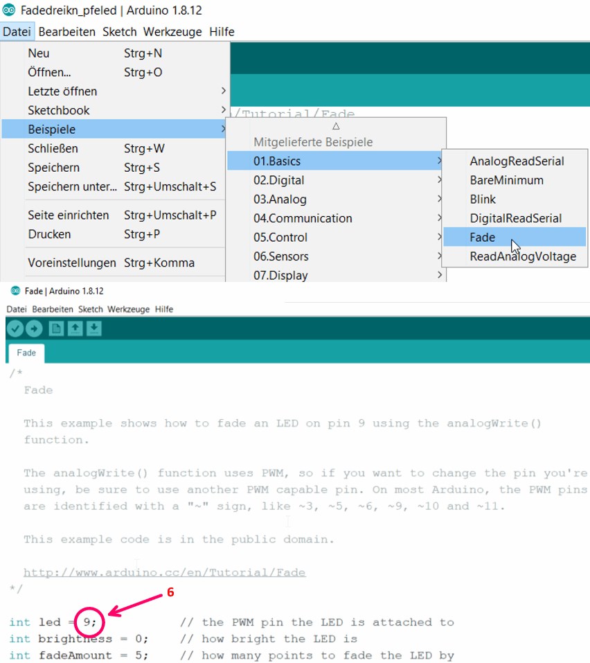
For the Arduino IDE we have to specify pin 6.
int led = 6;           // the PWM pin the LED is attached to
int brightness = 0;    // how bright the LED is
int fadeAmount = 5;    // how many points to fade the LED by

// the setup routine runs once when you press reset:
void setup() {
  // declare pin 6 to be an output:
  pinMode(led, OUTPUT);
}

// the loop routine runs over and over again forever:
void loop() {
  // set the brightness of pin 9:
  analogWrite(led, brightness);

  // change the brightness for next time through the loop:
  brightness = brightness + fadeAmount;

  // reverse the direction of the fading at the ends of the fade:
  if (brightness <= 0 || brightness >= 255) {
    fadeAmount = -fadeAmount;
  }
  // wait for 30 milliseconds to see the dimming effect
  delay(30);
}

With the programmer we now load the sketch onto the board.
The led gets lighter and darker.
measure what happens on the board
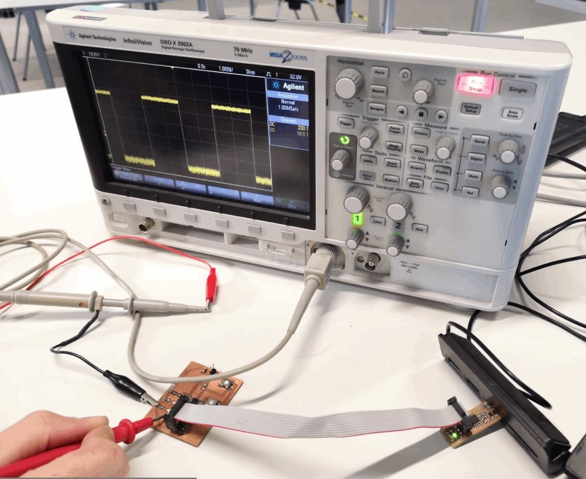
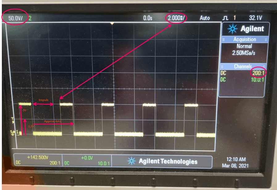
If we now look at the current flow on the oscilloscope, the PWM becomes readable. We have about 2 boxes from rising edge to rising edge. this corresponds to 4ms. This results in a frequency of 1 / 0.004, i.e. 250 Hz.