Networking Group Assignment

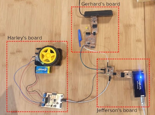
For the group assignment we are communicating 3 boards, Gerhard's board has a LDR photoresistor that senses the amount of light in the environment and turns on/off an LED connected to his board, the sensed value is sent via Serial Communication to Jefferson's board which also turns on an LED but also communicates via I2C with my board to activate/deactivate the motor based on the value sent by Gerhard's board.

Gerhard's code is:

// ==========================
// SENDER
// ==========================

#include 

SoftwareSerial softwareSerial(0, 1); // RX, TX

const int sendPin = 10; // LED pin
const int ldrPin = 9;  // LDR pin

void setup() {
  
  Serial.begin(9600);
  softwareSerial.begin(9600);

  pinMode(sendPin, OUTPUT);
  pinMode(ldrPin, INPUT);

  Serial.println("Sender ready");
}

void loop() {

  // Read ldr value
  int ldrStatus = analogRead(ldrPin);

  /******* Serial Monitor for debugging *******/
  Serial.print("[SENDING] Data: ");
  Serial.println(ldrStatus); // Displays the value of "ldrStatus" on the serial monitor

  /******* Send data to Reciver *******/
  softwareSerial.write(ldrStatus);

  if (ldrStatus <= 500) {
    digitalWrite(sendPin, HIGH);
    
    // for debugging
    //Serial.println("[STATUS] Its DARK Turn ON the LED");
  } else {
    digitalWrite(sendPin, LOW);

    // for debugging
    //Serial.println("[STATUS] Its BRIGHT Turn off the LED");
  }

  delay(200);

}
                     

Jefferson's code is:

// ==========================
// RECIVER
// ==========================

#include 
#include 

SoftwareSerial softwareSerial(0, 1); // RX, TX

#define LED 10 // LED pin

int data; // data from the sender

// Creates a object
FabMotorController MotorControl;

void setup() {

  Serial.begin(9600);
  softwareSerial.begin(9600);

  pinMode(LED, OUTPUT);

  Serial.println("Reciver ready");

  // Initializes I2C communication with the secondary at address 0x04
  MotorControl.begin(0x04);
}

void loop() {

  /* Read data from Sender */
  while (softwareSerial.available()){
    data = softwareSerial.read();
  }

  Serial.print("[RECIVER] data: ");
  Serial.println(data);

  if (data <= 125){
    digitalWrite(LED, HIGH);
    MotorControl.run(OUTPUT1, 100);

  }
  else{
    digitalWrite(LED, LOW);
    MotorControl.run(OUTPUT1, 0);
  }

  delay(200);
}
                     

My code is here

This is a demonstration video


Networking group assignment Jeff Josue

For this group assignment we had to communicate our boards with each other.

Boards used

- A ) The microcontroller board of my colleague Gerhard Mattisen.

- B ) The MyMiniBoard_X14 that I have made during the Electronics design assignment:
Features

- C ) The Fab Motor Controller of my colleague Harley Lara:
MotorController

Connections

Connection between boards:
Connection

  • Board A:

    • Has a photosensor as input.
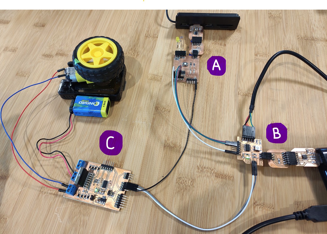
    • Sends the sensed values through serial connection to Board B.
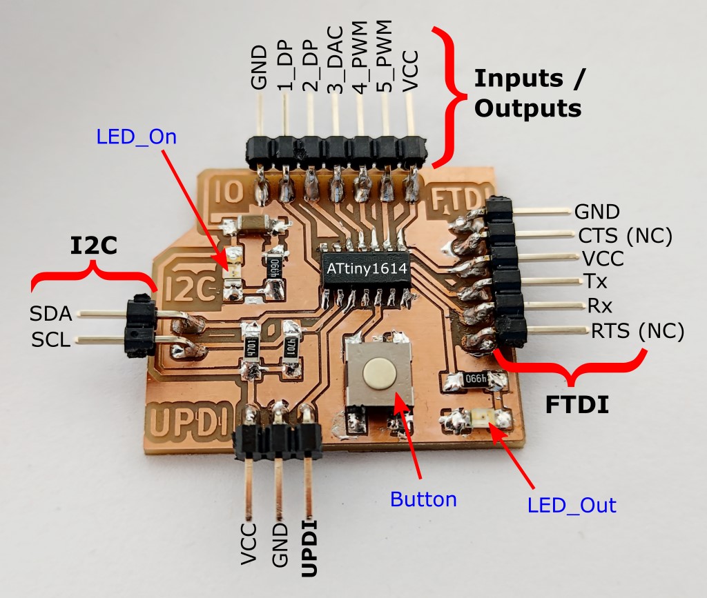
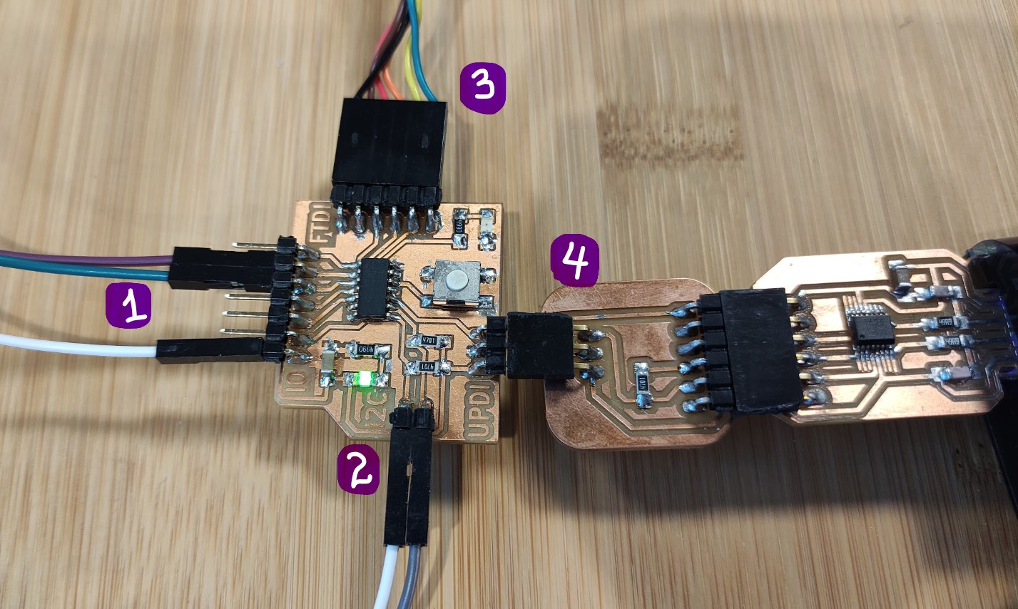
  • Board B:
    MyBoard

    • 1) is the Serial connection to Board A, receives sensed light intensity values;the board analyzes the values and according to them sends a message through ->
    • 2) I2C connection to Board C, to turn the motor On or Off.
    • 3) is FTDI for Serial monitor, and
    • 4) is UPDI for programming.
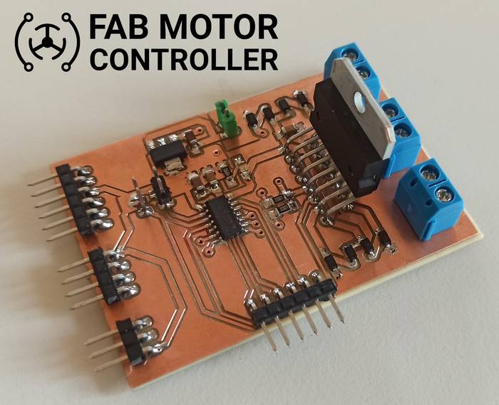
  • Board C:

    • Receives the messages from Board B to turn the DC motor On and Off.
    • Has a DC motor and a 9V battery connected.

Codes

Board A

 1
 2
 3
 4
 5
 6
 7
 8
 9
10
11
12
13
14
15
16
17
18
19
20
21
22
23
24
25
26
27
28
29
30
31
32
33
34
35
36
37
38
39
40
41
42
43
44
45
46
47
// ==========================
// SENDER
// ==========================

#include <SoftwareSerial.h>

SoftwareSerial softwareSerial(0, 1); // RX, TX

const int sendPin = 10; // LED pin
const int ldrPin = 9;  // LDR pin

void setup() {

  Serial.begin(9600);
  softwareSerial.begin(9600);

  pinMode(sendPin, OUTPUT);
  pinMode(ldrPin, INPUT);

  Serial.println("Sender ready");
}

void loop() {

  // Read ldr value
  int ldrStatus = analogRead(ldrPin);

  /** Serial Monitor for debugging **/
  Serial.print("[SENDING] Data: ");
  Serial.println(ldrStatus); // Displays the value of "ldrStatus" on the serial monitor

  /** Send data to Reciver **/
  softwareSerial.write(ldrStatus);

  if (ldrStatus <= 500) {
    digitalWrite(sendPin, HIGH);

    // for debugging
    //Serial.println("[STATUS] Its DARK Turn ON the LED");
  } else {
    digitalWrite(sendPin, LOW);

    // for debugging
    //Serial.println("[STATUS] Its BRIGHT Turn off the LED");
  }
  delay(200);
}

Board B

First I had to install the library that my colleague developed as his practice for this week.

 1
 2
 3
 4
 5
 6
 7
 8
 9
10
11
12
13
14
15
16
17
18
19
20
21
22
23
24
25
26
27
28
29
30
31
32
33
34
35
36
37
38
39
40
41
42
43
44
45
46
47
48
49
50
51
52
53
54
55
56
57
58
// ===========================
// Receiver
// ==========================

/* Made by Jefferson Sandoval in collaboration with Harley Lara 
 * for the Embedded Networking and Communications group assignment 
 * during the FabAcademy2021
 *  
 * This code was uploaded to a board with an Attiny1614 microcontroller
 * board. Board documentation:
 * http://fabacademy.org/2021/labs/kamplintfort/students/jefferson-sandoval/assignments/week07/
 * 
 * My documentation for this assignment:
 * http://fabacademy.org/2021/labs/kamplintfort/students/jefferson-sandoval/assignments/week14/
 */

#include <SoftwareSerial.h> //Include library to create an extra serial communication
#include <FabMotorController.h> //Include library to control Motor controller board

SoftwareSerial softwareSerial(0, 1); //Assign softwareSerial(RX, TX) pins
FabMotorController MotorControl; //Create an object

const int led = 10; //Declare constant for the built-in LED
int data; //Declare ingeter variable to read data from serial connection

void setup() {

  Serial.begin(9600); //Begin serial communication (used for monitor)
  softwareSerial.begin(9600); //Begin the extra serial communication

  pinMode(LED, OUTPUT); //Set LED as output

  Serial.println("Reciever ready"); //Starting serial monitor message

  MotorControl.begin(0x04); // Initialize I2C communication at address 0x04
}

void loop() {

  while (softwareSerial.available()){
    data = softwareSerial.read(); // Read data from Sender (Board A)
  }

  //Print the received values from Board A
  Serial.print("[RECEIVER] data: ");
  Serial.println(data);

  if (data <= 125){ //If the received value is less than 125 (darkness)...
    digitalWrite(LED, HIGH); //Turn on the built-in LED
    MotorControl.run(OUTPUT1, 100); //Send message to Board C to turn on the motor
  }
  else{ //else...
    digitalWrite(LED, LOW); //Turn off the built-in LED
    MotorControl.run(OUTPUT1, 0); //Send message to Board C to turn off the motor
  }

  delay(100);
}

Board C

Firmware that my colleague used:

  1
  2
  3
  4
  5
  6
  7
  8
  9
 10
 11
 12
 13
 14
 15
 16
 17
 18
 19
 20
 21
 22
 23
 24
 25
 26
 27
 28
 29
 30
 31
 32
 33
 34
 35
 36
 37
 38
 39
 40
 41
 42
 43
 44
 45
 46
 47
 48
 49
 50
 51
 52
 53
 54
 55
 56
 57
 58
 59
 60
 61
 62
 63
 64
 65
 66
 67
 68
 69
 70
 71
 72
 73
 74
 75
 76
 77
 78
 79
 80
 81
 82
 83
 84
 85
 86
 87
 88
 89
 90
 91
 92
 93
 94
 95
 96
 97
 98
 99
100
101
102
103
104
105
106
107
108
109
110
111
112
113
114
115
116
117
118
119
120
121
122
123
124
125
126
127
128
129
130
131
132
133
134
135
136
/*
 * FabMotorController Firmware v0.1
 * A Firmware to control through I2C the FabMotorController, 
 * a hardware based on the ATTINY1614 and the L298N driver.
 * 
 * Author: Harley Lara
 * Create: 01 May 2021
 * License: (CC BY-SA 4.0) Attribution-ShareAlike 4.0 International
 * 
 * This work may be reproduced, modified, distributed,
 * performed, and displayed for any purpose, but must
 * acknowledge this project. Copyright is retained and
 * must be preserved. The work is provided as is; no
 * warranty is provided, and users accept all liability.
 * 
 */

#include <Wire.h>

#define CONTROLLER_ADDR 0x04

/******* CONTROL PINs *******/
#define IN1 9   // OUTPUT 1 INPUT 1
#define IN2 8   // OUTPUT 1 INPUT 2
#define IN3 10  // OUTPUT 2 INPUT 1
#define IN4 2   // OUTPUT 2 INPUT 2
#define EN1 0   // 0 ENABLE 1 (PWM - SPEED CONTROL)
#define EN2 1   // 1 ENABLE 2 (PWM - SPEED CONTROL)

#define RESPONSE_SIZE 12
String response = "executing...";

void setup() {
  Wire.begin(CONTROLLER_ADDR);
  //Wire.onRequest(requestEvent); // TODO
  Wire.onReceive(receiveEvent);
  Serial.begin(115200);
  Serial.println("[INFO]: FAB MOTOR CONTROLLER - Starting ...");
  delay(20);

  // PINs Mode
  pinMode(IN1, OUTPUT);
  pinMode(IN2, OUTPUT);
  pinMode(IN3, OUTPUT);
  pinMode(IN4, OUTPUT);
  pinMode(EN1, OUTPUT);
  pinMode(EN2, OUTPUT);
}

unsigned char output;
int speed;
int direction;

void receiveEvent(){

  /******* Read data from Master *******/
  while (Wire.available()){
    output = Wire.read();
    speed =  Wire.read();
    direction = Wire.read();
  }

  /******* OUTPUT 1 *******/
  if (output == 1){
    Serial.println("[DEGUB]: OUTPUT 1");
    // Forward direction
    if (direction == 1){
      // stop output
      if (speed == 0){
        //Serial.println("[DEGUB]: OUTPUT 1 STOP FREE");
        digitalWrite(IN1, LOW);
        digitalWrite(IN2, LOW);
      }
      // moving output
      else{
        //Serial.println("[DEGUB]: OUTPUT 1 FORWARD");
        analogWrite(EN1, speed);
        digitalWrite(IN1, HIGH);
        digitalWrite(IN2, LOW);
      }
    }
    // backward direction
    else if (direction == 0){
      //Serial.println("[DEGUB]: OUTPUT 1 STOP FREE");
      if (speed == 0){
        digitalWrite(IN1, LOW);
        digitalWrite(IN2, LOW);
      }
      else{
        //Serial.println("[DEGUB]: OUTPUT 1 BACKWARD");
        analogWrite(EN1, speed);
        digitalWrite(IN1, LOW);
        digitalWrite(IN2, HIGH); 
      }
    }
  }

  /******* OUTPUT 2 *******/
  else if (output == 2){
    Serial.println("[DEGUB]: OUTPUT 2");
    // Forward direction
    if (direction == 1){
      // stop output
      //Serial.println("[DEGUB]: OUTPUT 2 STOP FREE");
      if (speed == 0){
        digitalWrite(IN3, LOW);
        digitalWrite(IN4, LOW);
      }
      // moving output
      //Serial.println("[DEGUB]: OUTPUT 2 FORWARD");
      else{
        analogWrite(EN2, speed);
        digitalWrite(IN3, HIGH);
        digitalWrite(IN4, LOW);
      }
    }
    // backward direction
    else if (direction == 0){
      if (speed == 0){
        //Serial.println("[DEGUB]: OUTPUT 2 STOP FREE");
        digitalWrite(IN3, LOW);
        digitalWrite(IN4, LOW);
      }
      else{
        //Serial.println("[DEGUB]: OUTPUT 2 BACKWARD");
        analogWrite(EN2, speed);
        digitalWrite(IN3, LOW);
        digitalWrite(IN4, HIGH); 
      }
    }
  }
}

void loop() {
  delay(50);
}

Performance

Then… when I cover the photosensor, the Motor is started: