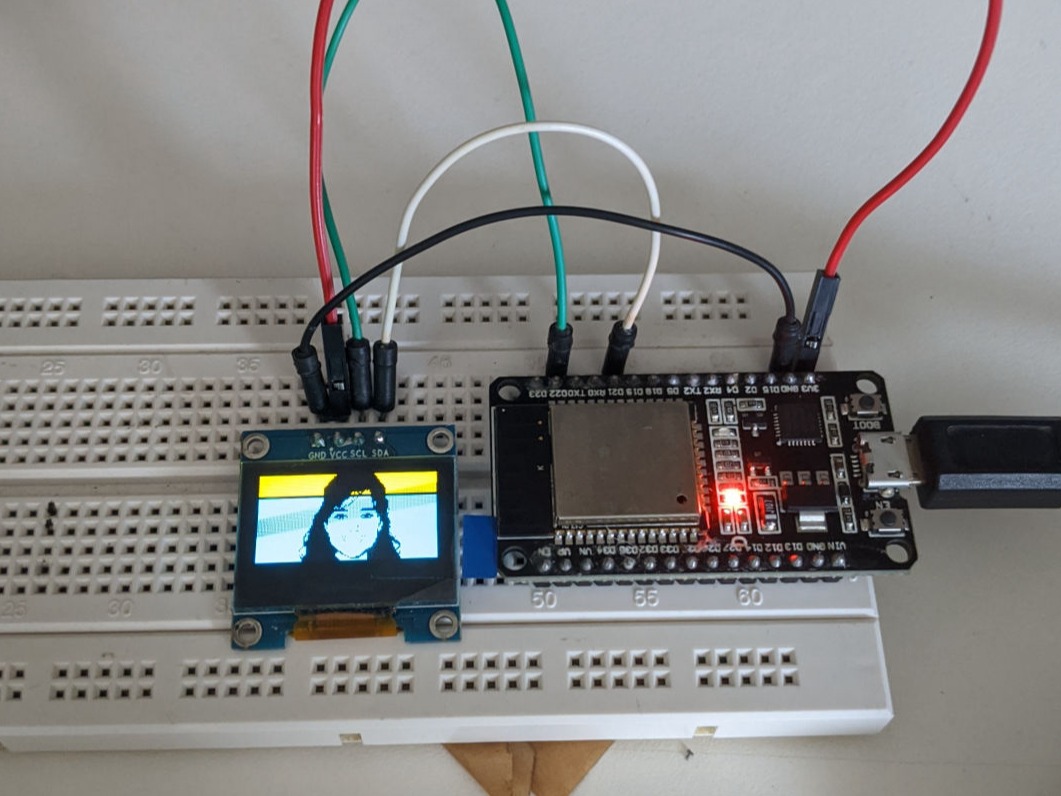
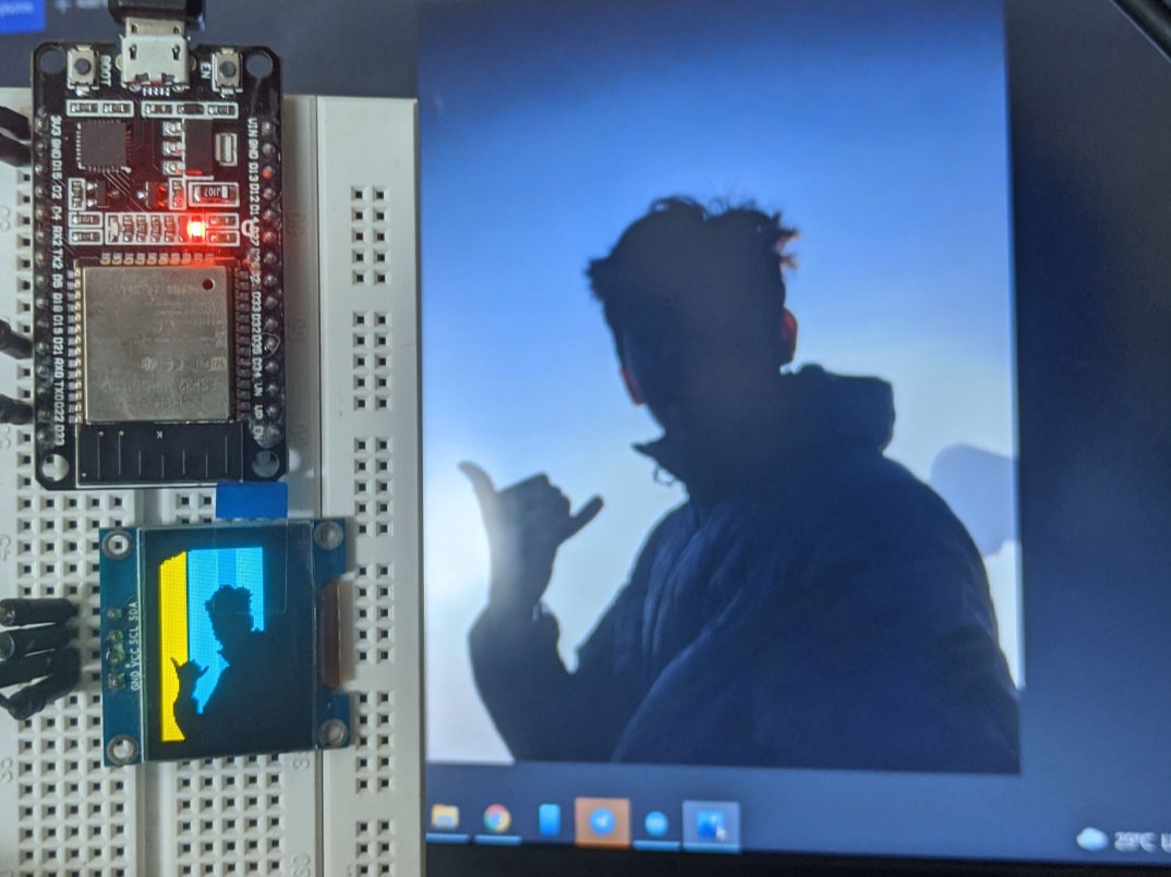
Copy the code below to display your bitmap image in the OLED.
#include< Wire.h >
#include <Adafruit_GFX.h >
#include <Adafruit_SSD1306.h>
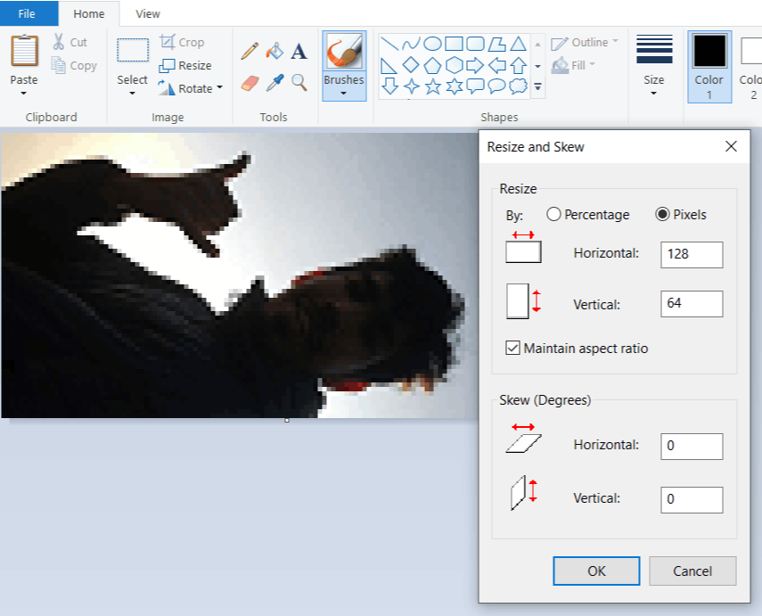
#define SCREEN_WIDTH 128
#define SCREEN_HEIGHT 64
Adafruit_SSD1306 display(SCREEN_WIDTH, SCREEN_HEIGHT, &Wire, -1);
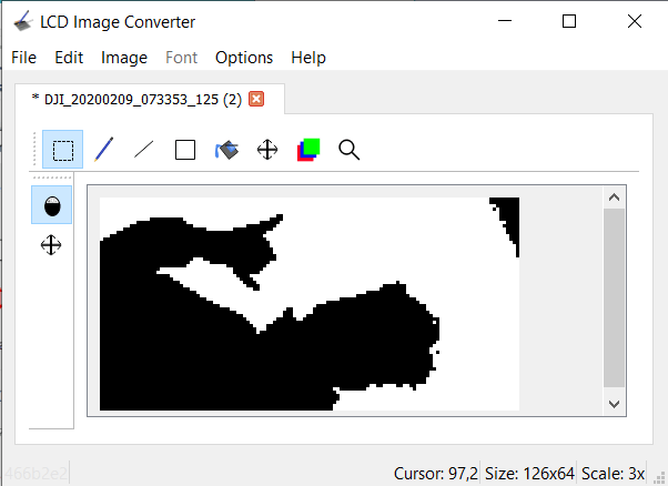
static const uint8_t image_data_Saraarray[1024] = {
0xff, 0xff, 0xff, 0xff, 0xff, 0xff, 0xff, 0xff, 0xff, 0xff, 0xff, 0xff, 0xff, 0xff, 0xf8, 0x00,
0xff, 0xff, 0xff, 0xff, 0xff, 0xff, 0xff, 0xff, 0xff, 0xff, 0xff, 0xff, 0xff, 0xff, 0xf8, 0x00,
0xff, 0xff, 0xff, 0xff, 0xff, 0xff, 0xff, 0xff, 0xff, 0xff, 0xff, 0xff, 0xff, 0xff, 0xfe, 0x00,
0xff, 0xff, 0xff, 0xff, 0xff, 0xff, 0xff, 0xff, 0xff, 0xff, 0xff, 0xff, 0xff, 0xff, 0xfd, 0x00,
0xff, 0xff, 0xff, 0xff, 0xff, 0xff, 0xff, 0xff, 0xff, 0xff, 0xff, 0xff, 0xff, 0xff, 0xff, 0x00,
0xff, 0xff, 0xff, 0xff, 0xff, 0xff, 0xf9, 0xff, 0xff, 0xff, 0xff, 0xff, 0xff, 0xff, 0xff, 0x00,
0xff, 0xfe, 0x00, 0x7f, 0xff, 0xff, 0xe1, 0xff, 0xff, 0xff, 0xff, 0xff, 0xff, 0xff, 0xff, 0x00,
0xff, 0xe0, 0x00, 0x3f, 0xff, 0xff, 0x03, 0xff, 0xff, 0xff, 0xff, 0xff, 0xff, 0xff, 0xff, 0xc0,
0xff, 0x80, 0x00, 0x0f, 0xff, 0xf0, 0x07, 0xff, 0xff, 0xff, 0xff, 0xff, 0xff, 0xff, 0xff, 0x80,
0xfe, 0x00, 0x00, 0x00, 0xff, 0x00, 0x0f, 0xff, 0xff, 0xff, 0xff, 0xff, 0xff, 0xff, 0xff, 0xc0,
0xf8, 0x00, 0x00, 0x00, 0x00, 0x00, 0x3f, 0xff, 0xff, 0xff, 0xff, 0xff, 0xff, 0xff, 0xff, 0xc0,
0xe0, 0x00, 0x00, 0x00, 0x00, 0x00, 0x7f, 0xff, 0xff, 0xff, 0xff, 0xff, 0xff, 0xff, 0xff, 0xe0,
0x80, 0x00, 0x00, 0x00, 0x00, 0x00, 0x3f, 0xff, 0xff, 0xff, 0xff, 0xff, 0xff, 0xff, 0xff, 0xe0,
0x00, 0x00, 0x00, 0x00, 0x00, 0x00, 0x1f, 0xff, 0xff, 0xff, 0xff, 0xff, 0xff, 0xff, 0xff, 0xf0,
0x00, 0x00, 0x00, 0x00, 0x00, 0x00, 0x1f, 0xff, 0xff, 0xff, 0xff, 0xff, 0xff, 0xff, 0xff, 0xf8,
0x00, 0x00, 0x00, 0x00, 0x00, 0x00, 0x0f, 0xff, 0xff, 0xff, 0xff, 0xff, 0xff, 0xff, 0xff, 0xf8,
0x00, 0x00, 0x00, 0x00, 0x00, 0x00, 0x0f, 0xff, 0xff, 0xff, 0xff, 0xff, 0xff, 0xff, 0xff, 0xf8,
0x00, 0x00, 0x00, 0x00, 0x00, 0x00, 0x07, 0xff, 0xff, 0xff, 0xff, 0xff, 0xff, 0xff, 0xff, 0xf8,
0x00, 0x00, 0x00, 0x0e, 0x00, 0x00, 0x07, 0xff, 0xff, 0xff, 0xff, 0xff, 0xff, 0xff, 0xff, 0xfc,
0x00, 0x00, 0x00, 0x1f, 0x80, 0x00, 0x1f, 0xff, 0xff, 0xff, 0xff, 0xff, 0xff, 0xff, 0xff, 0xfc,
0x00, 0x00, 0x00, 0x3f, 0xfc, 0x00, 0x3f, 0xff, 0xff, 0xff, 0xff, 0xff, 0xff, 0xff, 0xff, 0xfc,
0x00, 0x00, 0x3f, 0xff, 0xff, 0x00, 0x7f, 0xff, 0xff, 0xff, 0xff, 0xff, 0xff, 0xff, 0xff, 0xfc,
0x00, 0x00, 0x7f, 0xff, 0xff, 0x00, 0xff, 0xff, 0xff, 0xff, 0xff, 0xff, 0xff, 0xff, 0xff, 0xfc,
0x00, 0x00, 0x07, 0xff, 0xff, 0x87, 0xff, 0xff, 0xff, 0xff, 0xff, 0xff, 0xff, 0xff, 0xff, 0xfc,
0x00, 0x00, 0x03, 0xff, 0xff, 0xc3, 0xff, 0xff, 0xff, 0xff, 0xff, 0xff, 0xff, 0xff, 0xff, 0xfc,
0x00, 0x00, 0x00, 0xff, 0xff, 0xe1, 0xff, 0xff, 0xff, 0xff, 0xff, 0xbf, 0xff, 0xff, 0xff, 0xfc,
0x00, 0x00, 0x00, 0x7f, 0xff, 0xf0, 0xff, 0xff, 0xff, 0xff, 0xf8, 0x0f, 0xff, 0xff, 0xff, 0xfc,
0x00, 0x00, 0x00, 0x1f, 0xff, 0xfc, 0xff, 0xff, 0xff, 0xff, 0xf0, 0x0f, 0xff, 0xff, 0xff, 0xfc,
0x00, 0x00, 0x00, 0x07, 0xff, 0xff, 0xff, 0xff, 0xff, 0xff, 0x00, 0x0f, 0xff, 0xff, 0xff, 0xfc,
0x00, 0x00, 0x00, 0x03, 0xff, 0xff, 0xff, 0xff, 0xff, 0xf8, 0x00, 0x07, 0xff, 0xff, 0xff, 0xfc,
0x00, 0x00, 0x00, 0x00, 0xff, 0xff, 0xff, 0xff, 0xff, 0x00, 0x00, 0x01, 0xff, 0xff, 0xff, 0xfc,
0x00, 0x00, 0x00, 0x00, 0x3f, 0xff, 0xff, 0xff, 0xf0, 0x00, 0x00, 0x00, 0xff, 0xff, 0xff, 0xfc,
0x00, 0x00, 0x00, 0x00, 0x0f, 0xff, 0xff, 0xff, 0x80, 0x00, 0x00, 0x00, 0x3f, 0xff, 0xff, 0xfc,
0x00, 0x00, 0x00, 0x00, 0x01, 0xff, 0xff, 0x3f, 0x00, 0x00, 0x00, 0x00, 0x3f, 0xff, 0xff, 0xfc,
0x00, 0x00, 0x00, 0x00, 0x00, 0x7f, 0xfe, 0x3f, 0x00, 0x00, 0x00, 0x00, 0x1f, 0xff, 0xff, 0xfc,
0x00, 0x00, 0x00, 0x00, 0x00, 0x1f, 0xfe, 0x3c, 0x00, 0x00, 0x00, 0x00, 0x0f, 0xff, 0xff, 0xfc,
0x00, 0x00, 0x00, 0x00, 0x00, 0x0f, 0xf8, 0x18, 0x00, 0x00, 0x00, 0x00, 0x03, 0xff, 0xff, 0xfc,
0x00, 0x00, 0x00, 0x00, 0x00, 0x07, 0xf0, 0x00, 0x00, 0x00, 0x00, 0x00, 0x0b, 0xff, 0xff, 0xfc,
0x00, 0x00, 0x00, 0x00, 0x00, 0x03, 0xc0, 0x00, 0x00, 0x00, 0x00, 0x00, 0x03, 0xff, 0xff, 0xfc,
0x00, 0x00, 0x00, 0x00, 0x00, 0x01, 0xc0, 0x00, 0x00, 0x00, 0x00, 0x00, 0x03, 0xff, 0xff, 0xfc,
0x00, 0x00, 0x00, 0x00, 0x00, 0x01, 0x00, 0x00, 0x00, 0x00, 0x00, 0x00, 0x03, 0xff, 0xff, 0xfc,
0x00, 0x00, 0x00, 0x00, 0x00, 0x00, 0x00, 0x00, 0x00, 0x00, 0x00, 0x00, 0x03, 0xff, 0xff, 0xfc,
0x00, 0x00, 0x00, 0x00, 0x00, 0x00, 0x00, 0x00, 0x00, 0x00, 0x00, 0x00, 0x03, 0xff, 0xff, 0xfc,
0x00, 0x00, 0x00, 0x00, 0x00, 0x00, 0x00, 0x00, 0x00, 0x00, 0x00, 0x00, 0x07, 0xff, 0xff, 0xfc,
0x00, 0x00, 0x00, 0x00, 0x00, 0x00, 0x00, 0x00, 0x00, 0x00, 0x00, 0x00, 0x0f, 0xff, 0xff, 0xfc,
0x00, 0x00, 0x00, 0x00, 0x00, 0x00, 0x00, 0x00, 0x00, 0x00, 0x00, 0x00, 0x1f, 0xff, 0xff, 0xfc,
0x00, 0x00, 0x00, 0x00, 0x00, 0x00, 0x00, 0x00, 0x00, 0x00, 0x00, 0x00, 0x1b, 0xff, 0xff, 0xfc,
0x00, 0x00, 0x00, 0x00, 0x00, 0x00, 0x00, 0x00, 0x00, 0x00, 0x00, 0x00, 0x0f, 0xff, 0xff, 0xfc,
0x00, 0x00, 0x00, 0x00, 0x00, 0x00, 0x00, 0x00, 0x00, 0x00, 0x00, 0x00, 0x0f, 0xff, 0xff, 0xfc,
0x00, 0x00, 0x00, 0x00, 0x00, 0x00, 0x00, 0x00, 0x00, 0x00, 0x00, 0x00, 0x0f, 0xff, 0xff, 0xfc,
0x00, 0x00, 0x00, 0x00, 0x00, 0x00, 0x00, 0x00, 0x00, 0x00, 0x00, 0x00, 0x0f, 0xff, 0xff, 0xfc,
0x00, 0x00, 0x00, 0x00, 0x00, 0x00, 0x00, 0x00, 0x00, 0x00, 0x00, 0x00, 0x07, 0xff, 0xff, 0xfc,
0x00, 0x00, 0x00, 0x00, 0x00, 0x00, 0x00, 0x00, 0x00, 0x00, 0x00, 0x00, 0x1f, 0xff, 0xff, 0xfc,
0x00, 0x00, 0x00, 0x00, 0x00, 0x00, 0x00, 0x00, 0x00, 0x00, 0x00, 0x00, 0x1f, 0xff, 0xff, 0xfc,
0x00, 0x00, 0x00, 0x00, 0x00, 0x00, 0x00, 0x00, 0x00, 0x00, 0x00, 0x00, 0x3f, 0xff, 0xff, 0xfc,
0x00, 0x00, 0x00, 0x00, 0x00, 0x00, 0x00, 0x00, 0x00, 0x00, 0x00, 0x00, 0x3f, 0xff, 0xff, 0xfc,
0x00, 0x00, 0x00, 0x00, 0x00, 0x00, 0x00, 0x00, 0x00, 0x00, 0x67, 0x99, 0xff, 0xff, 0xff, 0xfc,
0x00, 0x00, 0x00, 0x00, 0x00, 0x00, 0x00, 0x00, 0x03, 0x00, 0xff, 0xfd, 0xff, 0xff, 0xff, 0xfc,
0x00, 0x00, 0x00, 0x00, 0x00, 0x00, 0x00, 0x00, 0x01, 0xff, 0xff, 0xff, 0xff, 0xff, 0xff, 0xfc,
0x00, 0x00, 0x00, 0x00, 0x00, 0x00, 0x00, 0x00, 0x00, 0xff, 0xff, 0xff, 0xff, 0xff, 0xff, 0xfc,
0x00, 0x00, 0x00, 0x00, 0x00, 0x00, 0x00, 0x00, 0x00, 0xff, 0xff, 0xff, 0xff, 0xff, 0xff, 0xfc,
0x00, 0x00, 0x00, 0x00, 0x00, 0x00, 0x00, 0x00, 0x01, 0xff, 0xff, 0xff, 0xff, 0xff, 0xff, 0xfc,
0x00, 0x00, 0x00, 0x00, 0x00, 0x00, 0x00, 0x00, 0x03, 0xff, 0xff, 0xff, 0xff, 0xff, 0xff, 0xfc,
0x00, 0x00, 0x00, 0x00, 0x00, 0x00, 0x00, 0x00, 0x03, 0xff, 0xff, 0xff, 0xff, 0xff, 0xff, 0xfc
};
void setup() {
Serial.begin(115200);
if (!display.begin(SSD1306_SWITCHCAPVCC, 0x3C)) {
Serial.println(F("SSD1306 allocation failed"));
for (;;);
}
delay(2000); // Pause for 2 seconds
// Clear the buffer.
display.clearDisplay();
// Draw bitmap on the screen
display.drawBitmap(0, 0, image_data_Saraarray, 128, 64, 1);
display.display();
}
void loop() {
}