Week 12
Output devices
Individual Assignment
For this week's individual assignment, I decided to make a board for a Servo Motor. I decided to go with the servo motor because I intend to use a servo motor for my final project. I planned to integrate the input for the final project along with this, so I can use it to do that too.
I am using the MG995 servo motor for this. I also tested using the 9g micro servo.The idea is to make the servo sweep angles with respect to the input from the ultrasonic sensor.
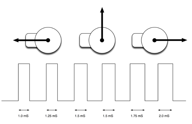
The position of the servo motor is set by the length of a pulse. The servo expects to receive a pulse roughly every 20 milliseconds. If that pulse is high for 1 millisecond, then the servo angle will be zero, if it is 1.5 milliseconds, then it will be at its centre position and if it is 2 milliseconds it will be at 180 degrees. The end points of the servo can vary and many servos only turn through about 170 degrees. You can also buy 'continuous' servos that can rotate through the full 360 degrees.
I first studied the data sheets of the servo motors.
MG995
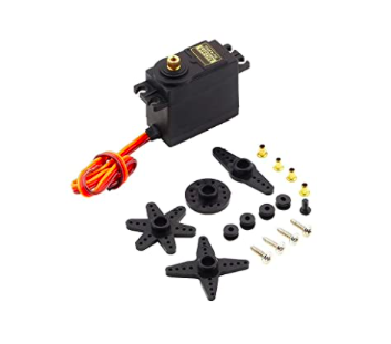
The MG995 servo motor data sheet can be obtained from here
TowerPro MG995 Metal Gear Servo Motor is a high-speed standard servo can rotate approximately 120 degrees (60 in each direction). We can use any servo code, hardware or library to control these servos, so it's great for beginners who want to make stuff move without building a motor controller with feedback & gear box, especially since it will fit in small places. The MG995 Metal Gear Servo also comes with a selection of arms and hardware to get you set up nice and fast. This is the most famous servo made by TowerPro . MG995 is a digital metal gear high torque servo for airplane, helicopter, RC-cars and many RC model This servo draws high current while operation (upto 2 amp in stall) , to make this servo work with arduino or any other micro controller , its important to ensure the following connections.
-The system should have a common ground
- A proper power source
SPECIFICATIONS AND FEATURES :
Weight : 55g
Dimension : 40.7 × 19.7 × 42.9 mm
Operating Speed : 1) 20sec / 60 deg (4.8V no load) 2) 16sec / 60 deg (6.0V no load)
Stall Torque : 1) 10 kg-cm at 4.8V 2) 12 kg-cm at 6V
Operation Voltage : 4.8 - 7.2Volts
Gear Type: All Metal Gears
Dead band width: 5 µs
Stable and shock proof double ball bearing design
Temperature range: 0 ºC – 55 ºC.
Control System : Analog
Operating Angle : 120degree
Required Pulse : 900us-2100us
DF9GMS
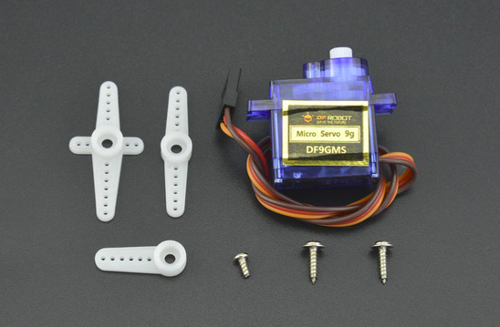
The DFRobot DF9GMS is a 360 degree micro servo. It uses a plastic gear drive and is light and compact. It can be used for various applications and DIY products, such as toy cars, boats, windmills etc. A 360 degree servo’s operation is more similar to a DC motor than a standard servo as only rotation direction and speed can be controlled. There is also no hardware stop inside so that the shaft can rotate freely. Compared to an ordinary DC motor, a 360-degree servo motor does not require additional motor drivers and is plug and play, compact and convenient. Arduino control methods are also the same. When the servo is operating on the 4.8 ~ 6V power supply, the torque can reach 1.2 ~ 1.6Kg x cm
SPECIFICATIONS AND FEATURES
Operating Voltage: 3.5 - 6.0V
Supply Voltage: 4.8V ~ 6.0V
Dead Zone Width: 5usec
Working Speed: 0.12sec/60 (4.8V no load)
Stall Torque: 1.2kg/cm (4.8V), 1.6kg/cm (6.0V)
Neutral Location: 1500us
Interface Description:
Brown: GND
Red: VCC
Orange: S
Cable Length: 250mm
Operating Temperature: -30°C to + 60°C
Dimensions: 22.6 x 12.2 x 30 mm /0.89x0.48x1.18”
Weight: 9±1g
Once that was done, I then decided to draw the circuit. I made a rough sketch on paper and then drew it on Eagle.
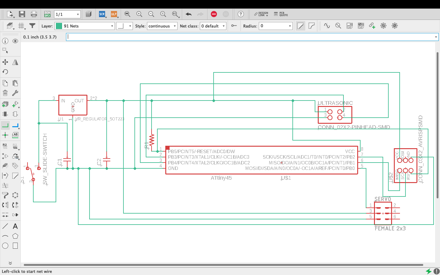
In the schematic, I also added a regulator circuit since I wanted to ensure my sensor is getting the right voltage.
After this, I converted it into a board, arranged the circuit and autorouted it.
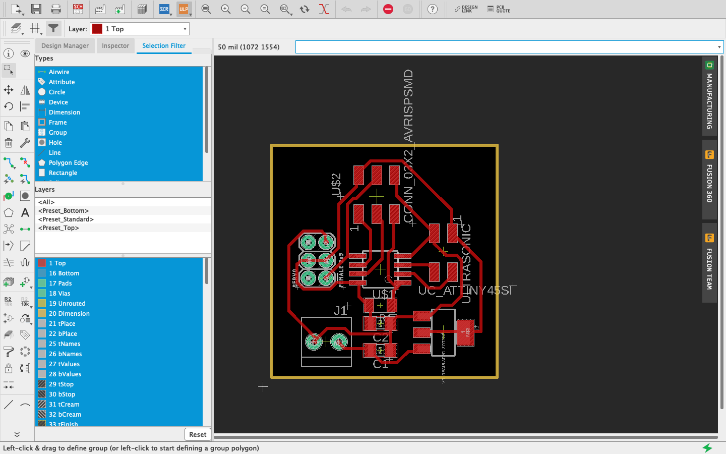
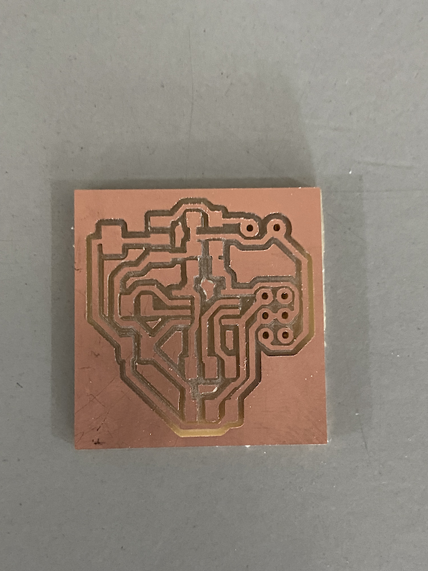
Then I hid the unwanted layers and exported the traces to mill. I then milled the circuit and got the board ready.
The cut looked like this
Then I soldered the board and added the following components
-ATtiny 45
-Resistors
-Connectors
-Connector for power
-Voltage regulator
Next I decided to code it. I wrote a code to sweep using the input from the ultrasonic sensor.
#include SoftwareServo.h
const int TRIG_PIN = 4;
const int ECHO_PIN = 3;
const int SERVO_PIN = 0;
const int DISTANCE_THRESHOLD = 10; // centimeters
SoftwareServo servo;
float duration_us, distance_cm;
void setup() {
// Serial.begin (9600);
pinMode(TRIG_PIN, OUTPUT);
pinMode(ECHO_PIN, INPUT);
servo.attach(SERVO_PIN);
servo.write(0);
}
void loop() {
// generate 10-microsecond pulse to TRIG pin
digitalWrite(TRIG_PIN, HIGH);
delayMicroseconds(10);
digitalWrite(TRIG_PIN, LOW);
// measure duration of pulse from ECHO pin
duration_us = pulseIn(ECHO_PIN, HIGH);
// calculate the distance
distance_cm = 0.017 * duration_us;
if(distance_cm < DISTANCE_THRESHOLD)
servo.write(90); // rotate servo motor to 90 degree
else
servo.write(0); // rotate servo motor to 0 degree
}
Once the coding was done, I decided to test the circuit using my Arduino
And it was giving me the desired output. So I decided to upload it to my board and try it.
Group Assignment
For this week's group assignment, the idea is to measure the power consumption of an output device. We know that Electric power is the rate, per unit time, at which electrical energy is transferred by an electric circuit. The SI unit of power is the watt (W), one joule per second. For measuring power we need, Volatage, Current and Resistance. The equations of power are:
P=V*I
P=I*I*R
P=(V*V)/R
Measuring Power
Volage is calculated by connecting parallel to the "Load". Here Units of Voltage is "Volt(V)"
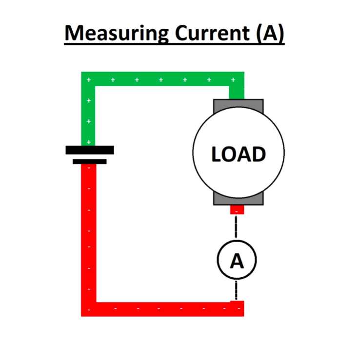
The Current is calculated by connecting series to the "Load".Here Units of Current is "Ampere(A)"

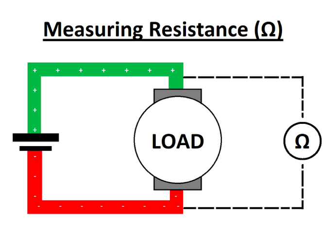
The Resistance is calculated by connecting parallel to the "Load"Here Units of Resistance is "Ohm(Ω)".
Files
The ino file can be downloaded from here